EP0454565A1 - Mikrowellen-Hohlraum zur Messung von elektromagnetischen Eigenschaften eines fadenförmigen Materials - Google Patents
Mikrowellen-Hohlraum zur Messung von elektromagnetischen Eigenschaften eines fadenförmigen Materials Download PDFInfo
- Publication number
- EP0454565A1 EP0454565A1 EP91401069A EP91401069A EP0454565A1 EP 0454565 A1 EP0454565 A1 EP 0454565A1 EP 91401069 A EP91401069 A EP 91401069A EP 91401069 A EP91401069 A EP 91401069A EP 0454565 A1 EP0454565 A1 EP 0454565A1
- Authority
- EP
- European Patent Office
- Prior art keywords
- cavity
- parts
- open
- microwave cavity
- orifices
- Prior art date
- Legal status (The legal status is an assumption and is not a legal conclusion. Google has not performed a legal analysis and makes no representation as to the accuracy of the status listed.)
- Withdrawn
Links
- 239000000463 material Substances 0.000 title claims abstract description 87
- 230000001681 protective effect Effects 0.000 claims abstract description 9
- 230000000295 complement effect Effects 0.000 claims description 13
- 238000005259 measurement Methods 0.000 abstract description 30
- 238000005520 cutting process Methods 0.000 abstract description 5
- 239000007788 liquid Substances 0.000 abstract description 3
- 239000007787 solid Substances 0.000 abstract description 2
- 238000012423 maintenance Methods 0.000 description 5
- 239000002131 composite material Substances 0.000 description 4
- 230000005684 electric field Effects 0.000 description 3
- 238000004519 manufacturing process Methods 0.000 description 3
- 229910001374 Invar Inorganic materials 0.000 description 2
- VYPSYNLAJGMNEJ-UHFFFAOYSA-N Silicium dioxide Chemical compound O=[Si]=O VYPSYNLAJGMNEJ-UHFFFAOYSA-N 0.000 description 2
- 239000000835 fiber Substances 0.000 description 2
- 239000011347 resin Substances 0.000 description 2
- 229920005989 resin Polymers 0.000 description 2
- OKTJSMMVPCPJKN-UHFFFAOYSA-N Carbon Chemical compound [C] OKTJSMMVPCPJKN-UHFFFAOYSA-N 0.000 description 1
- 230000002745 absorbent Effects 0.000 description 1
- 239000002250 absorbent Substances 0.000 description 1
- 230000004888 barrier function Effects 0.000 description 1
- 230000005540 biological transmission Effects 0.000 description 1
- 229910052799 carbon Inorganic materials 0.000 description 1
- 238000004140 cleaning Methods 0.000 description 1
- 238000011109 contamination Methods 0.000 description 1
- 230000005284 excitation Effects 0.000 description 1
- 230000005484 gravity Effects 0.000 description 1
- 238000003754 machining Methods 0.000 description 1
- 238000000034 method Methods 0.000 description 1
- 239000013307 optical fiber Substances 0.000 description 1
- 239000002245 particle Substances 0.000 description 1
- 235000011837 pasties Nutrition 0.000 description 1
- 230000035699 permeability Effects 0.000 description 1
- -1 polytetrafluoroethylene Polymers 0.000 description 1
- 229920001343 polytetrafluoroethylene Polymers 0.000 description 1
- 239000004810 polytetrafluoroethylene Substances 0.000 description 1
- 239000000377 silicon dioxide Substances 0.000 description 1
- 239000004753 textile Substances 0.000 description 1
- 239000011345 viscous material Substances 0.000 description 1
Images


Classifications
-
- G—PHYSICS
- G01—MEASURING; TESTING
- G01N—INVESTIGATING OR ANALYSING MATERIALS BY DETERMINING THEIR CHEMICAL OR PHYSICAL PROPERTIES
- G01N22/00—Investigating or analysing materials by the use of microwaves or radio waves, i.e. electromagnetic waves with a wavelength of one millimetre or more
Definitions
- the invention relates to a microwave cavity designed to be used in an industrial device making it possible to measure the electromagnetic characteristics such as the real and imaginary parts of the permissiveness or the permeability of a filiform material in continuous or discontinuous movement.
- Such a cavity can in particular be used, in association with a microwave source which ensures its excitation, to measure the electromagnetic characteristics of a polluting filiform composite material such as a wick impregnated with a viscous substance.
- the wick then consists of a multitude of fibers or fibrils made of a material such as carbon, electrically conductive, impregnated with a resin in the pasty or pre-gel state.
- the cavity according to the invention can however be used to measure the electromagnetic characteristics of a filiform material of a different nature, possibly non-composite, non-conductive and / or non-polluting.
- a microwave cavity for example closed cylindrical of the single-mode type, excited in a mode determined by a microwave source, to determine an electromagnetic quantity such that the complex permissiveness of a filiform material passing through the cavity.
- the filiform material then crosses the cavity by two opposite orifices formed in its wall, so as to be in a region of the cavity in which the magnetic or electric field, depending on the material to be tested, of a wave stationary established in the cavity is maximum and practically homogeneous.
- the electromagnetic characteristics of the material are calculated according to the evolution of the resonance curve of the cavity. This curve represents the variations of the transmitted power or the reflected power as a function of the resonant frequency, depending on whether the cavity has two or only one electrical measurement input-output.
- the measurement cavity can be polluted either by electrically conductive fibrils producing short circuits inside the resonant cavity, or by an excess of resin coming disturb the calibrations of the measurement system by flowing into the cavity.
- the operating point of the cavity i.e. the top of the resonance curve, is shifted towards a lower frequency and power compared to the operating point of the cavity in l absence of any pollution. The measurements carried out are therefore totally distorted.
- microwave cavity described in document FR-A-2 619 217 is ill-suited to industrial use. Indeed, it is not possible to introduce a long filiform material into the cavity without cutting the wick, or to ensure the maintenance of the device without stopping the operation of the measuring system.
- the subject of the invention is precisely a microwave cavity, the original design of which makes it possible to carry out measurements on an industrial scale on a moving filiform material, even in the case where this material is polluting, without it being necessary for any time to cut the filiform material, without the need to stop the measurements during maintenance operations and without risk of pollution of the cavity, even when these maintenance operations are carried out.
- a microwave cavity suitable for measuring the electromagnetic characteristics of a threadlike material in movement comprising a wall provided with two orifices facing each other allowing the passage of the material filiform, characterized in that the wall is also crossed by an open slot opening into the two orifices and the width of which allows the passage of the filiform material, a removable tubular protective device passing through the cavity between said orifices, this protective device comprising two open parts suitable for being juxtaposed edge to edge around the threadlike material.
- the open slot makes it possible to introduce the filiform material laterally into the orifices, to bring it into its measurement position, without it being necessary to cut this material.
- the tubular protection device makes it possible to protect the interior of the cavity from any pollution when the filiform material is a polluting material, and its production in two open parts allows its assembly and disassembly always without the need to cut the threadlike material.
- the tubular protection device can be introduced through one or other of the two orifices, so that its replacement is ensured by a simple push, the replacement device ejecting the used device, without any pollution. cannot even enter the cavity at this time.
- each of the open parts of the protection device has the shape of a half-cylinder of revolution.
- the open parts of the protection device have complementary lateral edges in the form of baffles, capable of being nested one inside the other.
- the open parts forming the tubular protection device can be fixed to either of the walls of the cavity by fixing members such as screws passing through holes formed in a fixing flange fitted to one of the ends of this part open.
- each of these parts comprises, opposite the end carrying the fixing flange, an end edge in the form of a baffle capable of being nested in an end edge complementary to an open replacement part inserted by sliding in the cavity.
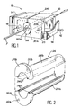
- the reference 10 generally designates a microwave cavity delimited by a wall 12 made, for example, of Invar.
- the shape as well as the dimensions of this cavity are adapted to the particular measurements which it is desired to carry out, according to the general knowledge of a person skilled in the art.
- the schematic representation of FIG. 1 should therefore not be considered as limiting from this point of view.
- the microwave cavity is a waveguide portion of rectangular section, closed at its ends by two short-circuits 14, also made of Invar and fixed to the wall 12 for example using screws 16.
- the wall 12 is crossed on one of its faces, near each of the attached walls 14, by an inlet 18 and by an outlet 20.
- the inlet 18 is intended to be coupled to a source microwave (not shown) and output 20 to a detector (not shown) by transmission cables (not shown).
- two of the parallel faces of the wall 12 of the cavity including the face in which the inlet 18 and the outlet 20 are formed, have in their center circular orifices 22 (FIGS. 3 and 4) arranged coaxially opposite one another.
- an open slot 24 passes through the wall 12 along a plane perpendicular to the longitudinal axis of the cavity and located equidistant from the short-circuits 14, so as to open into each of the two orifices 22 as well as outside the wall 12, on one of the faces of this wall oriented parallel to the axis common to the orifices 22.
- the location of the slot 24 is chosen so as to cut the minimum of magnetic field lines H or electric field for a device operating on the maximum electric field or magnetic field , respectively.
- the open slot 24 has a uniform width, for example of about 1.50 mm, chosen so as to allow the passage of the filiform material F in the direction of its least thickness (when it is a wick of material composite, the filiform material usually has a substantially rectangular section as illustrated in Figures 1, 3A and 3B).
- the face of the wall 12 opposite the slot 24 is reinforced by an increase in its thickness.
- a removable tubular protection device generally designated by the reference 26 in the figures is placed inside the circular orifices 22, so as to pass through its microwave cavity at its center.
- This protection device 26 thus surrounds the filiform material F, without however ensuring the guidance which is usually carried out on either side of the microwave cavity by appropriate means (not shown).
- the filiform material F is thus completely isolated from the interior of the cavity, so that any risk of pollution of the latter is avoided when the filiform material is a polluting material.
- the tubular protection device 26 is made of a material making it possible to disturb as little as possible the measurements carried out using the microwave cavity 10. In addition, this material is advantageously chosen so that the adhesion of the polluting particles or liquids therein be as low as possible.
- a material satisfying these two criteria simultaneously is polytetrafluoroethylene, whose dielectric constant is low (2.01) and whose non-stick characteristics are known. Silica can also be used.
- the introduction of the protection device 26 into the cavity increases its quality factor when empty from 10,000 to 8,000, which is negligible compared to the variation of this factor between the vacuum cavity and the cavity. loaded with absorbent material.
- the tubular protection device 26 more precisely has the shape of a cylinder of revolution whose uniform outside diameter is equal to the inside diameter of the circular orifices 22, so that the device can be inserted by sliding into these orifices.
- the internal diameter of the device 26 is chosen as for it as a function of the dimensions of the filiform material F, so as to avoid any friction of the latter against the wall of the device 26 without excessively increasing the diameter of the latter.
- this device is formed of two complementary open parts 28a and 28b, as illustrated on a larger scale the FIG. 2.
- Each of these open parts 28a, 28b has the shape of a half-cylinder of revolution whose length is preferably slightly greater than the width of the cavity 10 increased by the thickness of the two faces of the wall 12, in the direction of the axis common to the two orifices 22.
- Each of the parts 28a, 28b is produced in a single piece, advantageously obtained by machining from a different block, so as to reduce as much as possible the volume of material to be inside the cavity (to optimize the measurement system). For example, for a cavity of 1.93 x 105mm3, this volume can be approximately 350 mm3.
- each of the open parts 28a, 28b of the protective device 26 has a semi-circular shoulder or flange 30a, 30b facilitating handling and designed to be fixed to one or the other of the two faces of the wall 12 in which the orifices 22 are formed.
- This fixing is carried out by means of a screw (not shown) or of a similar fixing member passing through a hole 32a, 32b formed in each of the flanges 30a, 30b.
- the two holes 32a, 32b are located in diametrically opposite locations with respect to the axis of the cylinder of revolution thus formed. However, these holes 32a, 32b are offset relative to a plane of symmetry of each of the open parts 28a, 28b.
- the holes 32a, 32b are located opposite tapped holes 33 (FIGS. 3A and 3B) formed in the corresponding face of the wall 12 of the cavity, the joint plane of the two open parts 28a, 28b is oriented parallel to the other two faces of the wall 12.
- the lateral or longitudinal edges of the open parts 28a, 28b which are applied against each other to form the protection device 16 are flat edges contained in the joint plane passing through the axis common to these two open parts, which are then perfectly symmetrical.
- the lateral or longitudinal edges 34a and 34b of the two open parts 28a and 28b of the protection device 26 have complementary shapes constituting baffles when these edges 34a and 34b are nested one inside the other.
- the lateral edges 34a of the open part 28a have in section the shape of a projecting V while the lateral edges 34b of the second open part 28b have in section the shape of a reentrant V complementary to the protruding V formed by the edges 34a.
- the presence of the slot 24 as well as the production in two parts 28a, 28b of the protection device 26 make it possible, according to the invention, to introduce the filiform material F into the cavity microwave 10 and extract it at any location along the length of this material, without it being necessary to cut it or dismantle the cavity.
- FIG. 3A shows that before introducing the filiform material F, the operator sets up the open part 28a situated opposite the slot 24 by sliding it successively in each of the orifices 22 (arrow F1) .
- the flange 30a of this part 28a abuts against the corresponding face of the wall 12, it is fixed by means of a screw passing through the hole 32a, as described above.
- the filiform material passes through the slot 24 and is placed substantially along the axis of the half-cylinder formed by the part 28a previously installed.
- a protective sheath 35 constituted for example by a rolled sheet of paper, is placed around the part of the filamentary material F which must pass through the slot 24, in order to prevent sheets from entering the cavity.
- the operator can, if necessary, manually orient the filiform material F, so that this material passes through the slot 24 in the direction of its smallest thickness.
- the second open part 28b of the protection device 26 can in turn be introduced into the cavity by the same face as the first part 28a put in place previously.
- This introduction is again carried out by sliding through the orifices 22, the complementary lateral edges 34a and 34b sliding over one another.
- This operation is shown diagrammatically by the arrow F3 in FIG. 3B.
- the flange 30b of this second part 28b abuts against the corresponding face of the housing 12, it is fixed in turn by means of a screw passing through the hole 32b.
- the protective sheath 35 is then removed by sliding along the axis common to the filiform material F and to the protection device 24.
- the desired measurement can then be carried out on the filiform material F, by scrolling it continuously or discontinuously inside the protection device constituted by the two complementary parts 28a and 28b, practically without contact. with this device. Any liquid or solid pollution possibly brought by the filiform material F is then confined in the protection device and cannot penetrate into the cavity.
- the cavity 10 is oriented so that the axis common to the orifices 22 and to the complementary parts 28a, 28b of the protection device 26 is substantially vertical. This characteristic makes it possible to minimize the friction between the filiform material and the protection device and to evacuate by gravity part of the polluting deposits which tend to be deposited on the interior walls of the protection device.
- cleaning of these interior walls can also be carried out without stopping the measurements, for example by sending an air jet inside the protection device.
- one or both parts of this device can be disassembled, so as to be cleaned more completely.
- this disassembly of at least one of the two parts of the protection device consists in carrying out its replacement without interruption of the measurement and without the material barrier which this device constitutes being broken at any time.
- This replacement procedure will now be described with reference to Figures 4A to 4C.
- FIG. 4A very schematically represents the two open parts 28a, 28b of a protection device 26 mounted in the orifices 22 formed opposite one another in the wall 12 of a microwave cavity 10.
- the flanges 30a, 30b of these two parts 28a, 28b are fixed to one of the faces of the wall 12 comprising one of the orifices 22.
- the screws are removed by which the flanges 30a, 30b are fixed to the corresponding face of the wall 12 and the two parts are introduced through the orifice 22 formed in the opposite face of the wall 12 28′a, 28′b of a replacement device 26 ′ (arrow F4).
- this replacement is carried out in the direction of travel of the filiform material.
- the end edges 36′a, 36′b of each of these parts 28′a, 28′b situated opposite their flanges 30′a, 30′b are in abutment against the end edges 30a, 30b of the two parts 28a, 28b to be replaced, so that the latter are pushed back by the parts 28′a, 28′b.
- FIG. 4B at no time does the protection of the cavity against possible pollution produced by the filiform material F be interrupted.
- the end edges 36a, 36b situated opposite the flanges 30a, 30b on each of the parts 28a, 28b can be either flat edges, oriented radially with respect to to the axis of these parts 28a, 28b or non-planar edges.
- the edges 36a, 36b of the two parts 28a, 28b of the protection device 26 to be replaced are complementary to the edges 36′a, 36′b of the two parts 28′a, 28′b of the replacement device 26 ′.
- the non-planar complementary surfaces 36a, 36b and 36′a , 36′b form baffles which prevent any passage inside the cavity of mechanical pollution possibly introduced by the filiform material F. The protection of the cavity against pollution is thus complete, even when the device is replaced protection.
- the end edge 36a, 36b of each of the two parts 28a, 28b of the device 26 has in section the shape of a projecting V while the end edge 36′a, 36b of each of the two parts 28′a, 28′b of the device 26 ′ has in section the shape of a re-entrant V complementary to this protruding V.
- the parts 28′a, 28′b of the device 26 ′ are in turn replaced, parts 28a, 28b will again be used, the end edges of which form salient V sections.
- the microwave cavity according to the invention is perfectly suited to industrial use since the measurements can be carried out without it being necessary at any time to cut the filiform material while scrolling.
- the maintenance of the cavity can itself be carried out without interrupting the measurements and the quality of the latter can be preserved whatever the type of filiform material on which these measurements are carried out and in particular when this material is polluting.
- the characteristics of the invention can be transposed to microwave cavities of all shapes and sizes, the latter characteristics being determined in a known manner according to the nature of the measurements to be carried out.
- the microwave cavity according to the invention can be used to carry out measurements on a filiform material of any kind, whether this material is polluting or not, and independently of the fact that the scrolling of this material is carried out continuously or discontinuously.
- the invention can be used to measure deposits on textile threads or fibers, during their manufacture, or to carry out measurements and dimensional checks of a homogeneous material such as an optical fiber.
- the shape of the open parts constituting the removable tubular protection device can be different from that which has been described, these two parts being able in particular to be asymmetrical and not to have the shape of half-cylinders of revolution.
- the attachment of the two parts of the protection device can be done in a different way, without departing from the scope of the invention.
- the shapes of the lateral edges and of the end edges of these open parts may or may not be plane depending on the nature of the filiform material on which measurements are made.
- the material constituting the protection device can be any material having low losses and the volume of the device present in the cavity is not critical.
Landscapes
- Physics & Mathematics (AREA)
- Biochemistry (AREA)
- General Physics & Mathematics (AREA)
- Life Sciences & Earth Sciences (AREA)
- Chemical & Material Sciences (AREA)
- Analytical Chemistry (AREA)
- Electromagnetism (AREA)
- General Health & Medical Sciences (AREA)
- Health & Medical Sciences (AREA)
- Immunology (AREA)
- Pathology (AREA)
- Sampling And Sample Adjustment (AREA)
- Treatment Of Fiber Materials (AREA)
- Spinning Methods And Devices For Manufacturing Artificial Fibers (AREA)
- Measurement Of Resistance Or Impedance (AREA)
Applications Claiming Priority (2)
| Application Number | Priority Date | Filing Date | Title |
|---|---|---|---|
| FR9005265 | 1990-04-25 | ||
| FR9005265A FR2661500B1 (fr) | 1990-04-25 | 1990-04-25 | Cavite hyperfrequence adaptee a la mesure des caracteristiques electromagnetiques d'un materiau filiforme en defilement. |
Publications (1)
| Publication Number | Publication Date |
|---|---|
| EP0454565A1 true EP0454565A1 (de) | 1991-10-30 |
Family
ID=9396069
Family Applications (1)
| Application Number | Title | Priority Date | Filing Date |
|---|---|---|---|
| EP91401069A Withdrawn EP0454565A1 (de) | 1990-04-25 | 1991-04-23 | Mikrowellen-Hohlraum zur Messung von elektromagnetischen Eigenschaften eines fadenförmigen Materials |
Country Status (5)
| Country | Link |
|---|---|
| US (1) | US5103180A (de) |
| EP (1) | EP0454565A1 (de) |
| JP (1) | JPH04230838A (de) |
| CA (1) | CA2041086A1 (de) |
| FR (1) | FR2661500B1 (de) |
Families Citing this family (15)
| Publication number | Priority date | Publication date | Assignee | Title |
|---|---|---|---|---|
| DE69923571T2 (de) * | 1998-08-31 | 2006-01-12 | Malcam Ltd. | Mikrowellenresonator zur kontinuierlichen auswertung von faserigen stoffen |
| DE19854550C5 (de) * | 1998-11-26 | 2011-03-17 | Hauni Maschinenbau Ag | Resonatorgehäuse für Mikrowellen |
| US6375875B1 (en) * | 2000-01-27 | 2002-04-23 | Ut-Battelle, Llc | Diagnostic monitor for carbon fiber processing |
| DE10306217B4 (de) * | 2003-02-13 | 2014-06-26 | Rieter Ingolstadt Gmbh | Mikrowellenresonator, Textilmaschine mit einem derartigen Resonator sowie Raumeinheit für einen derartigen Resonator |
| DE10306209A1 (de) * | 2003-02-13 | 2004-08-26 | Rieter Ingolstadt Spinnereimaschinenbau Ag | Vorrichtung mit einem Mikrowellenresonator für eine oder an einer Spinnereivorbereitungsmaschine |
| DE10334144A1 (de) * | 2003-07-01 | 2005-01-20 | Rieter Ingolstadt Spinnereimaschinenbau Ag | Microwellenresonator, Textilmaschinen mit einem derartigen Resonator sowie Raumeinheit für einen derartigen Resonator |
| ITBO20060586A1 (it) * | 2006-08-03 | 2006-11-02 | El En Spa | Dispositivo per il taglio laser di un nastro continuo. |
| DE102006062339A1 (de) * | 2006-12-22 | 2008-07-03 | TRüTZSCHLER GMBH & CO. KG | Mikrowellenresonator für eine oder an einer Textilmaschine, insb. Karde, Strecke, Kämmmaschine o. dgl. |
| JP2010535325A (ja) * | 2007-08-02 | 2010-11-18 | ジー.デー ソチエタ ペル アツィオニ | 繊維性材料の特性を検出するための装置 |
| DE102011083051A1 (de) * | 2011-09-20 | 2013-03-21 | Hauni Maschinenbau Ag | Mikrowellenresonatorgehäuse |
| DE102013100644B4 (de) * | 2013-01-23 | 2020-04-30 | Rieter Ingolstadt Gmbh | Mikrowellenresonator für eine Textilmaschine |
| DE102014109651B4 (de) * | 2014-07-10 | 2023-05-11 | Rieter Ingolstadt Gmbh | Mikrowellenhohlraumresonator sowie damit ausgerüstete Spinnereivorbereitungsmaschine |
| GB2533418A (en) * | 2014-12-19 | 2016-06-22 | Salunda Ltd | Measurement of sugar in solution |
| CA3189654A1 (en) * | 2020-08-19 | 2022-02-24 | Chung Hoon Lee | Continuous heavy metal water contaminant measurement system |
| CN114136999B (zh) * | 2021-12-31 | 2025-01-21 | 西安热工研究院有限公司 | 一种互补开口谐振环电磁检测单元、检测系统及检测方法 |
Citations (4)
| Publication number | Priority date | Publication date | Assignee | Title |
|---|---|---|---|---|
| FR2386033A1 (fr) * | 1977-03-30 | 1978-10-27 | Bayer Ag | Dispositif de mesure de la teneur en eau d'une substance non conductrice de l'electricite |
| FR2556470A1 (fr) * | 1983-12-07 | 1985-06-14 | Bordeaux 1 Universite | Procede et dispositif de mesure en continu du taux d'impregnation de fibres conductrices |
| EP0302778A1 (de) * | 1987-08-04 | 1989-02-08 | AEROSPATIALE Société Nationale Industrielle | Vorrichtung zur stetigen Messung der Imprägnierungsrate elektrisch leitender oder nichtleitender Fasern mit einer Substanz |
| EP0372992A2 (de) * | 1988-12-09 | 1990-06-13 | E.I. Du Pont De Nemours And Company | Messapparatur und Verfahren unter Verwendung von Mikrowellenenergie |
Family Cites Families (2)
| Publication number | Priority date | Publication date | Assignee | Title |
|---|---|---|---|---|
| DE2848993A1 (de) * | 1978-11-11 | 1980-05-22 | Bayer Ag | Mikrowellenfeuchtemessgeraet mit umschaltbaren messbereichen |
| JPS63145951A (ja) * | 1986-12-09 | 1988-06-18 | Daipoole:Kk | 糸状材料の物性量測定装置 |
-
1990
- 1990-04-25 FR FR9005265A patent/FR2661500B1/fr not_active Expired - Fee Related
-
1991
- 1991-04-18 US US07/687,175 patent/US5103180A/en not_active Expired - Fee Related
- 1991-04-23 EP EP91401069A patent/EP0454565A1/de not_active Withdrawn
- 1991-04-24 CA CA002041086A patent/CA2041086A1/fr not_active Abandoned
- 1991-04-25 JP JP3122577A patent/JPH04230838A/ja active Pending
Patent Citations (4)
| Publication number | Priority date | Publication date | Assignee | Title |
|---|---|---|---|---|
| FR2386033A1 (fr) * | 1977-03-30 | 1978-10-27 | Bayer Ag | Dispositif de mesure de la teneur en eau d'une substance non conductrice de l'electricite |
| FR2556470A1 (fr) * | 1983-12-07 | 1985-06-14 | Bordeaux 1 Universite | Procede et dispositif de mesure en continu du taux d'impregnation de fibres conductrices |
| EP0302778A1 (de) * | 1987-08-04 | 1989-02-08 | AEROSPATIALE Société Nationale Industrielle | Vorrichtung zur stetigen Messung der Imprägnierungsrate elektrisch leitender oder nichtleitender Fasern mit einer Substanz |
| EP0372992A2 (de) * | 1988-12-09 | 1990-06-13 | E.I. Du Pont De Nemours And Company | Messapparatur und Verfahren unter Verwendung von Mikrowellenenergie |
Non-Patent Citations (1)
| Title |
|---|
| PATENT ABSTRACTS OF JAPAN vol. 12, no. 408 (P-778)(3255), 28 octobre 1988; & JP - A - 63145951 (DAIPOOLE K.K.) 18.06.1988 * |
Also Published As
| Publication number | Publication date |
|---|---|
| FR2661500B1 (fr) | 1994-01-07 |
| CA2041086A1 (fr) | 1991-10-26 |
| US5103180A (en) | 1992-04-07 |
| JPH04230838A (ja) | 1992-08-19 |
| FR2661500A1 (fr) | 1991-10-31 |
Similar Documents
| Publication | Publication Date | Title |
|---|---|---|
| EP0454565A1 (de) | Mikrowellen-Hohlraum zur Messung von elektromagnetischen Eigenschaften eines fadenförmigen Materials | |
| EP0302778B1 (de) | Vorrichtung zur stetigen Messung der Imprägnierungsrate elektrisch leitender oder nichtleitender Fasern mit einer Substanz | |
| EP0325874B1 (de) | Verfahren und Vorrichtung zum Bestimmen der Zeitspanne, die eine Flüssigkeit zur Änderung ihres physischen Zustandes benötigt | |
| EP0114140A1 (de) | Abstimmbarer Mikrowellenfilter mit dielektrischen Resonatoren im TM010 Modus | |
| EP0271413B1 (de) | Isolationsverschiebungssteckverbinder für Einzelleiterkabel | |
| EP0186558B1 (de) | Vorrichtung zur Stoffstrahlenbehandlung durch Elektronenstrahl | |
| EP0035922A1 (de) | Abstimmungsvorrichtung mit veränderbarer Kapazität und abstimmbares Mikrowellenfilter mit wenigstens einer solchen Vorrichtung | |
| EP0225235A1 (de) | Rohrschneidevorrichtung | |
| EP0263031B1 (de) | Induktiv gekoppelte Luft-Plasma-Vorrichtung für die spektrometrische Analyse von Elementen | |
| EP0060174A1 (de) | Bandpassfilter mit dielektrischen Resonatoren | |
| WO2007010134A1 (fr) | Adapteur d'impedance automatique coaxial | |
| EP0508854A1 (de) | Gerät zum fortlaufenden und berührungslosen Messen der Dicke einer dünnen, leitenden Schicht auf einem isolierenden Träger, zum Beispiel einer vorbeilaufenden Fiber oder Folie | |
| EP0006556A1 (de) | Verfahren und Vorrichtung zum Abgeben einer bestimmten Flüssigkeitsmenge in ein Gefäss | |
| EP2887451B1 (de) | Hyperfrequenz-Bandpassfilter, der durch Drehung eines dielektrischen Elements abstimmbar ist | |
| EP0533534B1 (de) | Gerät zum Absorbieren oder Ausstrahlen von Licht zu berührungslosen Objektvermessung | |
| FR2556470A1 (fr) | Procede et dispositif de mesure en continu du taux d'impregnation de fibres conductrices | |
| FR3026480B1 (fr) | Procede de detection d'un ecart de meches dans un tissu de fibres et dispositif pour sa mise en oeuvre | |
| FR2707396A1 (fr) | Procédé et dispositif de détection de défauts d'homogénéité dans une bande ou feuille mince en matériau diélectrique. | |
| EP0340081B1 (de) | Rohrschneidvorrichtung | |
| EP0096608B1 (de) | Faseroptischer Kollimator, Anwendung zur Realisierung optischer Schaltervorrichtungen | |
| FR2618252A1 (fr) | Gyrotron a ondes progressives protege contre les modes indesires. | |
| FR2622366A1 (fr) | Dispositif permettant de denuder l'extremite d'un cable | |
| FR2639768A1 (fr) | Dispositif de propagation des micro-ondes pour materiau plan en defilement, notamment textile | |
| WO2007031639A1 (fr) | Filtre a guide d'onde pour micro-ondes a parois non paralleles | |
| FR2630257A1 (fr) | Tube a onde progressive comportant un dispositif de couplage entre sa ligne a retard et des circuits hyperfrequences externes |
Legal Events
| Date | Code | Title | Description |
|---|---|---|---|
| PUAI | Public reference made under article 153(3) epc to a published international application that has entered the european phase |
Free format text: ORIGINAL CODE: 0009012 |
|
| AK | Designated contracting states |
Kind code of ref document: A1 Designated state(s): BE CH DE ES GB IT LI NL SE |
|
| 17P | Request for examination filed |
Effective date: 19920410 |
|
| 17Q | First examination report despatched |
Effective date: 19940425 |
|
| STAA | Information on the status of an ep patent application or granted ep patent |
Free format text: STATUS: THE APPLICATION IS DEEMED TO BE WITHDRAWN |
|
| 18D | Application deemed to be withdrawn |
Effective date: 19940906 |