EP0454571A1 - Identifikations- und Kontrollsiegel - Google Patents
Identifikations- und Kontrollsiegel Download PDFInfo
- Publication number
- EP0454571A1 EP0454571A1 EP91401080A EP91401080A EP0454571A1 EP 0454571 A1 EP0454571 A1 EP 0454571A1 EP 91401080 A EP91401080 A EP 91401080A EP 91401080 A EP91401080 A EP 91401080A EP 0454571 A1 EP0454571 A1 EP 0454571A1
- Authority
- EP
- European Patent Office
- Prior art keywords
- link
- seal according
- male
- plate
- female
- Prior art date
- Legal status (The legal status is an assumption and is not a legal conclusion. Google has not performed a legal analysis and makes no representation as to the accuracy of the status listed.)
- Withdrawn
Links
Images

Classifications
-
- G—PHYSICS
- G09—EDUCATION; CRYPTOGRAPHY; DISPLAY; ADVERTISING; SEALS
- G09F—DISPLAYING; ADVERTISING; SIGNS; LABELS OR NAME-PLATES; SEALS
- G09F3/00—Labels, tag tickets, or similar identification or indication means; Seals; Postage or like stamps
- G09F3/02—Forms or constructions
- G09F3/03—Forms or constructions of security seals
- G09F3/0305—Forms or constructions of security seals characterised by the type of seal used
- G09F3/0347—Forms or constructions of security seals characterised by the type of seal used having padlock-type sealing means
- G09F3/0352—Forms or constructions of security seals characterised by the type of seal used having padlock-type sealing means using cable lock
-
- G—PHYSICS
- G09—EDUCATION; CRYPTOGRAPHY; DISPLAY; ADVERTISING; SEALS
- G09F—DISPLAYING; ADVERTISING; SIGNS; LABELS OR NAME-PLATES; SEALS
- G09F3/00—Labels, tag tickets, or similar identification or indication means; Seals; Postage or like stamps
- G09F3/02—Forms or constructions
- G09F3/03—Forms or constructions of security seals
- G09F3/0305—Forms or constructions of security seals characterised by the type of seal used
- G09F3/037—Forms or constructions of security seals characterised by the type of seal used having tie-wrap sealing means
Definitions
- the present invention relates to an identification and control seal.
- the seal according to the invention finds a particular but nonlimiting use as an identification and control bracelet for slaughtered game.
- bracelets It is known for hunting certain types of game to distribute bracelets in a determined number corresponding to the number of pieces of game that can be killed, this in order to ensure the sustainability of the species.
- the bracelets are intended to be fixed inviolably on a leg or a tendon or on the neck of the killed game.
- the bracelets are formed in a known manner of a flexible link whose ends must be secured by a seal once placed on the game.
- the present invention aims to overcome this drawback by proposing an identification and control seal avoiding multiple uses.
- Another object of the seal according to the invention is to ensure an inviolable and rapid closure. Yet another purpose of the seal is to make the identification of the object or animal on which it is placed easy and secure.
- the seal according to the invention is provided with at least one marking plate, with a link, and with means for closing the loop formed by said link and is essentially characterized in that the link is integral detachably over all or part of its length from the marking plate, in that it comprises at one of its ends a male or female part of the closing means and is fixedly secured to the plate at a point distant from its end carrying said male or female part.
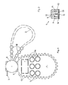
- the identification and control seal comprises at least one marking plate 1 on which certain inscriptions can be made, a link 2 intended to form a loop for attaching the seal to object or animal and means of closure inviolable of the loop formed by the link 2.
- the seal is provided with a single marking plate 1.
- the closing means comprise a male part 3 and a female part 4 intended to cooperate in closing with each other to keep the loop formed by the link 2 closed.
- the link 2 of the seal according to the invention is detachably secured over all or part of its length of the marking plate 1, has at one of its ends the male part 3 or female 4 of the closure means and is secured so fixed of the marking plate 1 at a point distant along its length from the end carrying the said male or female part.
- the end of the link 2 not carrying the male or female part of the closure means is fixedly secured to the marking plate 1.
- the other part of the closure means is integral in a non-detachable manner with the marking plate.
- the link 2 is detachably secured to the marking plate over all or part of its length from its end carrying the male part 3 or female 4 of the closure means.
- the link 2 is detachably secured to the plate 1 over its entire length and on the periphery of said plate.
- the connection 2 to the marking plate 1 is secured by a plurality of weak points 5 established over the entire length of the link 2 and on the periphery of the plate 1 and breaking under the effect of a traction.
- One of the ends of the link 2 carries the male 3 or female 4 part of the closure means which is also detachably secured to the marking plate 1.
- the loop can be formed and then closed by cooperation of the male 3 and female 4 parts.
- the link 2 can be secured to the plate 1 detachably only over part of its length but from its end carrying the male part 3 or female 4 of the closure means.
- the rupture of the points of weakness 5 formed from this end also constitutes a presumption of use of the seal.
- the end of the detachable link 2 carries the male part 3 of the closing means, the female part 4 being secured in a non-detachable manner to the marking plate 1 but it goes without saying that the reverse can be achieved.
- the male part 3 of the closure means comprises a base 6, on which are projecting two parallel tabs 7 spaced from one another and each having on their outer face a barb 8 .
- the faces of the legs 7 facing each other are divergent at the ends of said legs.
- the latter are preferably slightly elastic.
- the base 6 is preferably in the form of a disc and the link 2 is fixed there radially.
- the female part 4 of the closing means as shown in FIGS. 1 and 2 is constituted by a cube 9 fixed to the marking plate 1 so as to be projecting with respect to a face of the plate.
- This cube 9 is preferably fixed at the periphery of the plate 1.
- a housing 10 passing right through it and preferably opening onto the faces of said cube parallel to the plate 1.
- the housing 10 is intended to receive the tabs 7 of the male part and to retain the latter irremovably.
- two parallel faces of the housing 10 are provided each of a shoulder 11 on which the barbs 8 of the tabs 7 are clipped, thus preventing the withdrawal of the male part 3.
- the shoulders 11 are produced obliquely so that the barbs 8 come to bear by their surface thereon.
- the angle of inclination of the barbs 8 and the shoulders 11 is the same.
- the housing 10 is provided in its entry area of the male part 3 with a central partition 12 formed parallel to the faces provided with the shoulders 11. This partition 12 is intended to be placed between the tabs 7 of the male part 3 to center and guide the latter in order to ensure correct and irremovable closure.
- the housing 10 of the cube 9 is obstructed by a cover 13 fixed in a non-removable manner in a recess 14 formed on the face of the cube 9 parallel to that provided with the inlet of the housing 10.
- the cover 13 is fixed in the recess 14 by any known means and preferably by welding and so that it cannot be removed.
- this female part 4 of the closing means is made all the easier by the presence of this cover 13.
- Said cover is provided on its inner face to the housing 10 with a holding element for spacing the tabs 7 of the male part.
- This spacing holding element consists of a wedge-shaped projection 15 intended to be placed in the extension of the partition 12 and to keep the legs apart. 7 of the male part so that the barbs 8 thereof are held against the shoulders 11 of the housing 10.
- the legs 7 come into contact with the conical projection 15 by the diverging ends of their opposite face. Due to the cooperation of the barbs 8 with the shoulders 11, the wedge-shaped projection 15 keeping the legs 7 apart and the inaccessibility inside the housing 10, the means for closing the seal according to the invention are inviolable.
- a countersink (not shown) in which is housed the base 6 of the male part 3 so that said base is not protruding on the cube 9 and therefore n 'offer no grip on a tool for an attempt to break the seal closing means.
- the base 6 may have a contour which follows the shape of a square.
- the link 2 attaching laterally to the base, it will be made in the bead defining the counterbore, a notch for the passage of the link.
- the female part 4 of said closing means is formed on the periphery of the marking plate 1.
- the link 2 is integral in a non-detachable manner by one of its ends of said female part while the other end of said link carries the male part 3.
- Said male part is detachably secured to the female part 4 by means of a point of weakness 5.
- the separation of the link 2 is done first by breaking the weak point 5 between the male part 3 and the female part 4 then by breaking the other weak points 5 between the said link and the periphery of the plate 1, the part male 3 which can then cooperate in closing with the female part 4 thus locking the loop formed by the link 2.
- the marking plate 1 of the seal according to the invention is equipped with at least one detachable area 16 which can receive an inscription and a non-detachable surface also receiving inscriptions.
- said marking plate is provided with means making it possible to determine a date.
- These means are constituted by detachable zones 16, for example, the number of 6 defining a month and by studs 17 formed at the periphery of the plate and for example the number of 31 defining the days.
- Said pads are preferably circular, thus giving the plate 1 a scalloped edge.
- these circular studs allow the attachment at a point of the link 2.
- the latter is detachably fixed to the plate 1 by points of weakness 5 established between itself and the studs 17.
- studs 17 can be removed using a cutting tool.
- spherical bosses 18 on each of which is the point of weakness 5.
- These spherical bosses 18 are preferably the same number as the studs 17.
- the spherical shape of the bosses 18 and the circular shape of the studs 17 makes it easier to produce the points of weakness 5.
- the marking plate 1 also includes an orifice 19 allowing the passage of a wire on which several seals according to the invention can be placed for their transport. As shown, the marking plate 1 has an ovoid shape without this being limiting.
- the ends of the link 2 each carry respectively the male part 3 and the female part 4 of the closure means.
- Said link is fixed in a non-detachable manner to the plate 1 in the middle part of its length and is secured to the periphery of the plate in a detachable manner between its non-detachable fixing point and its ends.
- the seal according to the invention is preferably made of plastic and is produced by injection molding.
- the seal avoids multiple uses by creating a presumption of use from its first use, is easy and inviolable closure and allows to identify and date the object or animal on which it is placed.
- the present invention can receive all arrangements and all variants in the field of technical equivalents without departing from the scope of this patent.
Landscapes
- Engineering & Computer Science (AREA)
- Computer Security & Cryptography (AREA)
- Physics & Mathematics (AREA)
- General Physics & Mathematics (AREA)
- Theoretical Computer Science (AREA)
- Closures For Containers (AREA)
- Package Frames And Binding Bands (AREA)
Applications Claiming Priority (2)
| Application Number | Priority Date | Filing Date | Title |
|---|---|---|---|
| FR9005606 | 1990-04-27 | ||
| FR9005606A FR2661537B1 (fr) | 1990-04-27 | 1990-04-27 | Sceau d'identification et de controle. |
Publications (1)
| Publication Number | Publication Date |
|---|---|
| EP0454571A1 true EP0454571A1 (de) | 1991-10-30 |
Family
ID=9396308
Family Applications (1)
| Application Number | Title | Priority Date | Filing Date |
|---|---|---|---|
| EP91401080A Withdrawn EP0454571A1 (de) | 1990-04-27 | 1991-04-23 | Identifikations- und Kontrollsiegel |
Country Status (2)
| Country | Link |
|---|---|
| EP (1) | EP0454571A1 (de) |
| FR (1) | FR2661537B1 (de) |
Cited By (2)
| Publication number | Priority date | Publication date | Assignee | Title |
|---|---|---|---|---|
| EP1076327A3 (de) * | 1999-08-07 | 2001-03-21 | Spirent plc | Sicherheitsbehälter |
| US20230193663A1 (en) * | 2021-12-21 | 2023-06-22 | John Paul LAWRENCE | Self-locking tie cords and systems, and related methods of use |
Citations (5)
| Publication number | Priority date | Publication date | Assignee | Title |
|---|---|---|---|---|
| US1964897A (en) * | 1932-08-31 | 1934-07-03 | George J Wenk | Self-locking seal |
| US3367701A (en) * | 1966-01-14 | 1968-02-06 | American Casting And Mfg Corp | Self-locking plastic seal |
| EP0176120A1 (de) * | 1984-09-01 | 1986-04-02 | Halbe Jacobus Niemeijer | Kennzeichnungssiegel |
| CH667773A5 (en) * | 1986-06-11 | 1988-11-15 | Biwi Sa | Marker tag for animals - comprises flexible strip with ends equipped with two halves of pressure fixing |
| US4793641A (en) * | 1987-06-09 | 1988-12-27 | Panduit Corp. | Tamper revealing seal |
-
1990
- 1990-04-27 FR FR9005606A patent/FR2661537B1/fr not_active Expired - Lifetime
-
1991
- 1991-04-23 EP EP91401080A patent/EP0454571A1/de not_active Withdrawn
Patent Citations (5)
| Publication number | Priority date | Publication date | Assignee | Title |
|---|---|---|---|---|
| US1964897A (en) * | 1932-08-31 | 1934-07-03 | George J Wenk | Self-locking seal |
| US3367701A (en) * | 1966-01-14 | 1968-02-06 | American Casting And Mfg Corp | Self-locking plastic seal |
| EP0176120A1 (de) * | 1984-09-01 | 1986-04-02 | Halbe Jacobus Niemeijer | Kennzeichnungssiegel |
| CH667773A5 (en) * | 1986-06-11 | 1988-11-15 | Biwi Sa | Marker tag for animals - comprises flexible strip with ends equipped with two halves of pressure fixing |
| US4793641A (en) * | 1987-06-09 | 1988-12-27 | Panduit Corp. | Tamper revealing seal |
Cited By (3)
| Publication number | Priority date | Publication date | Assignee | Title |
|---|---|---|---|---|
| EP1076327A3 (de) * | 1999-08-07 | 2001-03-21 | Spirent plc | Sicherheitsbehälter |
| US20230193663A1 (en) * | 2021-12-21 | 2023-06-22 | John Paul LAWRENCE | Self-locking tie cords and systems, and related methods of use |
| US12269660B2 (en) * | 2021-12-21 | 2025-04-08 | John Paul LAWRENCE | Self-locking tie cords and systems, and related methods of use |
Also Published As
| Publication number | Publication date |
|---|---|
| FR2661537A1 (fr) | 1991-10-31 |
| FR2661537B1 (fr) | 1992-08-14 |
Similar Documents
| Publication | Publication Date | Title |
|---|---|---|
| FR2598905A1 (fr) | Dispositif d'interruption de la circulation d'un fluide dans un conduit a paroi souple, notamment un viscere creux et ensemble de pince comportant ce dispositif | |
| FR2498912A1 (fr) | Cadre pour l'exposition d'objets | |
| EP0466656B1 (de) | Armbandverschluss | |
| WO2002021952A1 (fr) | Perfectionnement aux dispositifs de serrage pour gants de protection en cotte de mailles | |
| LU85659A1 (fr) | Gaines pour rasoirs de securite | |
| FR2543717A1 (fr) | Distributeur multiple de ruban pour le marquage de composants et fils electriques | |
| EP2134162B1 (de) | Fessel für einen identifikationsring | |
| EP0454571A1 (de) | Identifikations- und Kontrollsiegel | |
| FR2692763A1 (fr) | Fermoir pour objets de joaillerie-bijouterie tels que bracelets, colliers. | |
| CH667773A5 (en) | Marker tag for animals - comprises flexible strip with ends equipped with two halves of pressure fixing | |
| FR2688477A3 (fr) | Dispositif de fixation irreversible d'un accessoire sur le col d'une bouteille. | |
| EP0238518A1 (de) | Rahmenartiger kartenhalter | |
| FR2580595A1 (fr) | Attache pour relier le bouchon a la goulotte d'un reservoir | |
| EP2625115B1 (de) | Manipulationssichere drahtkappe | |
| FR2536730A1 (fr) | Dispositif pour ramasser un materiau en forme de fil | |
| EP2229671B1 (de) | Bindung für einen identifikationsring mit verschlusselement | |
| FR2934126A1 (fr) | Ensemble de bijoux compose d'au moins trois pieces solidarisees entre elles. | |
| FR2750020A1 (fr) | Ensemble de percage par boucle d'oreille pour pistolets dits a goujons | |
| EP0738480B1 (de) | Gelenkvorrichtung zum Verbinden von Armbandgliedern | |
| CA2424939A1 (fr) | Dispositif de fixation et/ou d'assemblage | |
| FR2705447A1 (fr) | Dispositif de grappage de bombes d'artifice et retard pyrotechnique pouvant être utilisés conjointement dans un dispositif de tir de feu d'artifice. | |
| FR2730381A1 (fr) | Dispositif de fermeture de poche ostreicole | |
| FR2779626A1 (fr) | Barrette dissuasive pour la presentation de bijoux | |
| FR2481576A1 (fr) | Etui de protection pour hamecon | |
| EP0968646B1 (de) | Fälschungssicherer Anhänger oder Ohrmarke zur Tiermarkierung |
Legal Events
| Date | Code | Title | Description |
|---|---|---|---|
| PUAI | Public reference made under article 153(3) epc to a published international application that has entered the european phase |
Free format text: ORIGINAL CODE: 0009012 |
|
| AK | Designated contracting states |
Kind code of ref document: A1 Designated state(s): BE CH DE ES FR GB IT LI NL |
|
| 17P | Request for examination filed |
Effective date: 19920217 |
|
| 17Q | First examination report despatched |
Effective date: 19950308 |
|
| GRAG | Despatch of communication of intention to grant |
Free format text: ORIGINAL CODE: EPIDOS AGRA |
|
| GRAH | Despatch of communication of intention to grant a patent |
Free format text: ORIGINAL CODE: EPIDOS IGRA |
|
| STAA | Information on the status of an ep patent application or granted ep patent |
Free format text: STATUS: THE APPLICATION IS DEEMED TO BE WITHDRAWN |
|
| 18D | Application deemed to be withdrawn |
Effective date: 19960723 |