EP0454574A1 - Lösbare Vorrichtung zur axialen Festlegung eines glatten Rohres in einem Anschlussstück - Google Patents
Lösbare Vorrichtung zur axialen Festlegung eines glatten Rohres in einem Anschlussstück Download PDFInfo
- Publication number
- EP0454574A1 EP0454574A1 EP91401084A EP91401084A EP0454574A1 EP 0454574 A1 EP0454574 A1 EP 0454574A1 EP 91401084 A EP91401084 A EP 91401084A EP 91401084 A EP91401084 A EP 91401084A EP 0454574 A1 EP0454574 A1 EP 0454574A1
- Authority
- EP
- European Patent Office
- Prior art keywords
- sleeve
- washer
- inlet bore
- tube
- cylindrical housing
- Prior art date
- Legal status (The legal status is an assumption and is not a legal conclusion. Google has not performed a legal analysis and makes no representation as to the accuracy of the status listed.)
- Withdrawn
Links
- 238000000605 extraction Methods 0.000 claims description 3
- 230000000284 resting effect Effects 0.000 claims description 3
- 230000008878 coupling Effects 0.000 abstract 1
- 238000010168 coupling process Methods 0.000 abstract 1
- 238000005859 coupling reaction Methods 0.000 abstract 1
- 239000002184 metal Substances 0.000 description 6
- 235000021183 entrée Nutrition 0.000 description 5
- 238000007789 sealing Methods 0.000 description 4
- 239000000463 material Substances 0.000 description 3
- 238000004873 anchoring Methods 0.000 description 2
- 238000000429 assembly Methods 0.000 description 2
- 238000002788 crimping Methods 0.000 description 2
- 230000003100 immobilizing effect Effects 0.000 description 2
- 238000004519 manufacturing process Methods 0.000 description 2
- 208000031968 Cadaver Diseases 0.000 description 1
- 239000007788 liquid Substances 0.000 description 1
Images

Classifications
-
- F—MECHANICAL ENGINEERING; LIGHTING; HEATING; WEAPONS; BLASTING
- F16—ENGINEERING ELEMENTS AND UNITS; GENERAL MEASURES FOR PRODUCING AND MAINTAINING EFFECTIVE FUNCTIONING OF MACHINES OR INSTALLATIONS; THERMAL INSULATION IN GENERAL
- F16L—PIPES; JOINTS OR FITTINGS FOR PIPES; SUPPORTS FOR PIPES, CABLES OR PROTECTIVE TUBING; MEANS FOR THERMAL INSULATION IN GENERAL
- F16L37/00—Couplings of the quick-acting type
- F16L37/08—Couplings of the quick-acting type in which the connection between abutting or axially overlapping ends is maintained by locking members
- F16L37/084—Couplings of the quick-acting type in which the connection between abutting or axially overlapping ends is maintained by locking members combined with automatic locking
- F16L37/0844—Couplings of the quick-acting type in which the connection between abutting or axially overlapping ends is maintained by locking members combined with automatic locking by means of a ring pivoting so as to lie against the tube
Definitions
- End caps which allow the quick and tight connection of a smooth, rigid or semi-rigid tube, the axial fixing of the tube in the end piece being ensured by a rigid annular washer, generally subjected to the action of a spring. , whose internal periphery is capable of being anchored in the wall of the tube.
- Such tips are described in particular in US-A-2,360,732 and in FR-A-1,403,312 and 1,535,163.
- the axial immobilization device of the smooth tube can be assembled on the body of a nozzle, one end of which is shaped to receive a flexible pipe fixed by means of a clamp.
- the tip body can receive at each of its ends a device for immobilizing a smooth tube.
- the tip body will generally have two aligned ends, but nothing prevents us from imagining that this tip body has three ends (T-fitting) or even four ends (cross fitting).
- connection end pieces can have stocks of standard sub-assemblies which will be assembled to end piece bodies according to the needs of the customers.
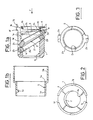
- an axial immobilization device of a smooth tube as it can be stored at a manufacturer of connection fittings. It consists of a set of five functional elements, some of which are pre-assembled.
- a sleeve 1 preferably made of plastic, defines a cylindrical housing 1 a intended to receive, on the one hand, at least one metal washer 2 , on the other hand, an elastic member 3 , such as a helical spring, arranged between the washer 2 and a support stop 4 , itself located or fixed at one of the ends of the sleeve 1 .
- an elastic member 3 such as a helical spring, arranged between the washer 2 and a support stop 4 , itself located or fixed at one of the ends of the sleeve 1 .
- These first four elements are completed by a ring 5 , known as an unlocking ring, capable of being slidably mounted on the sleeve 1 .
- the sleeve 1 At its end, located to the left of FIG. 1 a , the sleeve 1 has a bore 1 b whose diameter - which will correspond substantially to that of the tube received by a connection piece - is less than that of the cylindrical housing 1 a .
- the end face 1 c of the bore located to the right of the figure, is inclined relative to the axis of the sleeve 1 and thus constitutes a plane internal shoulder in the housing 1 a .
- the wall of the sleeve 1 has a longitudinal slot 1 d preferably opening at the right end of the sleeve and extending to the left only as far as the vicinity of the inlet bore 1 b .
- the slot 1 d will advantageously arranged, as seen in the drawings, in the diametral plane of the sleeve, perpendicular to the plane of the internal shoulder 1 c , on the side where the bore 1 b has the shortest length.
- a second longitudinal slot 1 e similar to the slot 1 d , is provided in the region diametrically opposite the latter; however, the length of the slot 1 e is smaller than that of the slot 1 d , since it extends only as far as the vicinity of the internal shoulder 1 c , on the side where the bore 1 b has the most great length.
- the sleeve 1 At its end opposite to the inlet bore 1b , the sleeve 1 has an external shoulder 1f , extending to the right by a conical inlet 1g .
- the housing 1 a ends in an annular groove 1 h , the largest diameter of which is greater than the smallest internal diameter of the conical inlet 1 g .
- the shoulder 1 f is advantageous because it makes it possible to limit the thickness of the wall of the sleeve in the region of the housing 1 a .
- this shoulder 1 f will constitute an external stop under conditions which will be specified below.
- the metal washer 2 has an outside diameter close to that of the housing 1 a and preferably slightly smaller than the latter, so that it can easily slide in the housing when it is perpendicular to the axis of the latter.
- the internal diameter of the washer 2 is itself close to that of the inlet bore 1b and preferably at most equal thereto.
- the orifice 2 a of the washer is advantageously delimited, on the side opposite to the inlet bore, by a small cylindrical shoulder 2 b whose role will appear later.
- the edges of the hole 2 has, on each side of the washer 2 are preferably sharp edges whose role will also stressed further.
- the washer 2 is sufficient in a large number of applications, it may be advantageous to provide a second washer 2 ′ whose inside and outside diameters as well as the edges of the orifice are practically identical to those of the washer 2 .
- the washer 2 and, where appropriate, the washer 2 ′ comprise at least one radial projection 2 c and 2 ′ c , the width of which is close to that of the slot 1 d of the sleeve and the radial height of which is preferably at more equal to the thickness of the wall of the sleeve in the region of the cylindrical housing 1 a .
- a slot 1 e could be provided on the sleeve 1 .
- a radial projection 2 d (or 2 ′ d ), diametrically opposite to the radial projection 2 c (or 2 ′ c ), the shapes correspond to those of slot 1 e .
- the washer 2 can bear on the internal plane shoulder 1 c of the sleeve, if necessary by means of the washer 2 ′ .
- the washer 2 (as well as the washer 2 ′ ) can also be brought to occupy a position (represented in dotted line) perpendicular to the axis of the sleeve, its orifice then being aligned with the inlet bore 1b .
- An elastic member 3 is supported on an abutment 4 disposed within the housing 1a of the sleeve, exerts its force on the face of the washer 2, opposite the inlet bore 1 b, and keeps the latter in an inclined position, of preferably resting (possibly via the washer 2 ′ ) on the internal shoulder 1 c of the sleeve.
- the elastic member 3 is a helical spring whose first turn surrounds the cylindrical shoulder 2b of the washer 2 and is thus guided by the latter.
- the turns of the spring 3 or any other spare resilient member in the housing 1 has a space whose diameter is at least equal to that of the bore 1b.
- the supporting stop may be integral with the sleeve 1 or preferably be constituted by an annular metal plate 4 whose central aperture 4a, delimited by an edge 4b directed towards the inlet bore 1 b, has a diameter at least equal to that of said bore.
- the circular groove formed by the edge 4b receives the end turn of the spring 3 .
- the outer periphery of the plate 4 has a diameter and a thickness corresponding substantially to those of the groove 1 h of the sleeve.
- a ring 5 preferably made of plastic, essentially has a first cylindrical portion 5 a , the inside diameter of which corresponds substantially to the outside diameter of the sleeve so that it can slide on the latter.
- a second cylindrical portion 5 b the internal diameter of which is greater than that of the first portion, extends the latter portion to which it is connected by a radial wall 5 c .
- An internal radial projection 5 d is provided in the first portion of the ring. Its width is at most equal to that of the slot 1 d of the sleeve while its height is close to the thickness of the wall of the housing 1 a and preferably at most equal to this thickness.
- the length of the first portion 5 a of the ring and the axial position of the projection 5 d on this first portion are determined in such a way that the ring always covers the inlet end of the sleeve, whatever the position of the projection 5 d in slot 1 d .
- To the left the sliding of the ring on the sleeve is limited by the support of the radial projection on the end of the slot 1 d
- this movement is limited by the support of the radial wall 5 c on the shoulder 1 f of the sleeve.
- the washer 2, and optionally the washer 2 ' take the positions shown in Figure 1a and the assembly thus mounted can be stored with the ring 5 before being manipulated to form a complete nozzle connection for smooth tube.
- the body A receives by fitting a flexible pipe B which is immobilized by a clamp C.
- the body A has, on the one hand, a cylindrical housing A1 with an axial stop for receiving the smooth tube T to be connected, on the other hand, a groove A2 for an annular sealing ring E. Note that this groove is open at the end of the tip body, although this arrangement is not essential.
- the tip body A preferably has a protruding conical shape A3 extended to the right by a cylindrical part itself defining a shoulder A4 with the rest of the body A.
- the assembly of a sub-assembly previously described on a tip body is then carried out after having paired the two elements so that the outside diameter of the shoulder 1 f is substantially equal to that of the shoulder A4 of the tip body and that the diameter of the inlet bore 1b is substantially equal to that of the cylindrical housing A1 of the body.
- the fixing of body A on the immobilization sub-assembly is obtained by a simple crimping of the free end (initially in the position shown in dotted lines) of the ring 6 behind the shoulder A4 of the body A.
- the unlocking ring 5 is finally threaded onto the sleeve 1 , its internal radial projection 5 d being forced beyond the inlet bore 1 b to come and take place in the slot 1 d of the sleeve.
- the larger diameter portion 5b of the ring 5 somewhat covers the ring 6 when the projection 5 d is in contact with the closed end of the slot 1 d .
- the ring 5 constitutes a sealing member preventing any introduction of unwanted element into the slots 1 d and 1 e .
- connection of a smooth tube T is carried out simply by making it penetrate into the complete end piece through the bore 1b until it reaches the bottom of the housing A1 of the body.
- the tube T pushes the washer 2 (and possibly the washer 2 ') which rotate in the housing 1 to the sleeve to take the position shown in broken lines in Figure 1b.
- the orifice 2 a can then be crossed by the tube T which, after having crossed the rod E by pushing it back into the groove A2 , will reach the bottom of the housing A1 .
- We know that the extraction of the tube T from the nozzle is normally prevented by anchoring certain portions of the sharp edges of the orifice 2 a of the washer 2 (and possibly of the washer 2 ′ ) in the outer wall of the tube.
- the latter may be made of a rigid material, such as a metal, or semi-rigid, such as a plastic material, the end fittings of the type described do not present any particular constraint in this regard.
- the body A10 is cylindrical and has two opposite housings A11 and A12 for the two tubes as well as two grooves A21 and A22 , similar to the groove A2 of the end body described above, for the sealing rods E1 and E2 .
- the projecting conical ends A31 and A32 of the body are connected to one another by a cylindrical portion A14 .
- the second sub-assembly is then engaged, from right to left, in the free end of the ring 16 and the fixing of the three elements is obtained by a simple crimping of this free end (initially in the position shown in dotted lines) behind the shoulder 1 f of the second sub-assembly.
- the end piece is finally completed by mounting the unlocking rings 5 of each of the tube immobilization subassemblies under the same conditions as those described with reference to FIG. 4.
Landscapes
- Engineering & Computer Science (AREA)
- General Engineering & Computer Science (AREA)
- Mechanical Engineering (AREA)
- Quick-Acting Or Multi-Walled Pipe Joints (AREA)
Applications Claiming Priority (2)
| Application Number | Priority Date | Filing Date | Title |
|---|---|---|---|
| FR9005287A FR2661463B1 (fr) | 1990-04-25 | 1990-04-25 | Dispositif deverrouillable pour l'immobilisation axiale d'un tube lisse dans un embout. |
| FR9005287 | 1990-04-25 |
Publications (1)
| Publication Number | Publication Date |
|---|---|
| EP0454574A1 true EP0454574A1 (de) | 1991-10-30 |
Family
ID=9396084
Family Applications (1)
| Application Number | Title | Priority Date | Filing Date |
|---|---|---|---|
| EP91401084A Withdrawn EP0454574A1 (de) | 1990-04-25 | 1991-04-24 | Lösbare Vorrichtung zur axialen Festlegung eines glatten Rohres in einem Anschlussstück |
Country Status (5)
| Country | Link |
|---|---|
| EP (1) | EP0454574A1 (de) |
| JP (1) | JPH04228993A (de) |
| CS (1) | CS119091A2 (de) |
| FR (1) | FR2661463B1 (de) |
| HU (1) | HUT58873A (de) |
Cited By (1)
| Publication number | Priority date | Publication date | Assignee | Title |
|---|---|---|---|---|
| EP0618394A3 (de) * | 1993-04-02 | 1995-01-04 | Walther Carl Kurt Gmbh | Verriegelungseinrichtung an Steckkupplungen. |
Citations (2)
| Publication number | Priority date | Publication date | Assignee | Title |
|---|---|---|---|---|
| CH462560A (de) * | 1966-08-29 | 1968-09-15 | Bengesser Karl | Klemmkupplung |
| US4842309A (en) * | 1987-05-20 | 1989-06-27 | Schmelzer Corporation | Quick-connect fluid fitting assembly |
Family Cites Families (1)
| Publication number | Priority date | Publication date | Assignee | Title |
|---|---|---|---|---|
| SU1280254A1 (ru) * | 1983-09-28 | 1986-12-30 | Московский станкостроительный завод "Красный пролетарий" им.А.И.Ефремова | Устройство дл быстроразъемного соединени шлангов |
-
1990
- 1990-04-25 FR FR9005287A patent/FR2661463B1/fr not_active Expired - Lifetime
-
1991
- 1991-04-24 EP EP91401084A patent/EP0454574A1/de not_active Withdrawn
- 1991-04-24 HU HU137491A patent/HUT58873A/hu unknown
- 1991-04-25 CS CS911190A patent/CS119091A2/cs unknown
- 1991-04-25 JP JP9518291A patent/JPH04228993A/ja active Pending
Patent Citations (2)
| Publication number | Priority date | Publication date | Assignee | Title |
|---|---|---|---|---|
| CH462560A (de) * | 1966-08-29 | 1968-09-15 | Bengesser Karl | Klemmkupplung |
| US4842309A (en) * | 1987-05-20 | 1989-06-27 | Schmelzer Corporation | Quick-connect fluid fitting assembly |
Non-Patent Citations (1)
| Title |
|---|
| Soviet Inventions Illustrated Derwent Publications Ltd., Section Mécanique, semaine 8732, abrégé no.227880, Q67,19 août 1987 & SU-A-1280254 (MOSC MACH TOOL WKS) 30 décembre 1986 * |
Cited By (1)
| Publication number | Priority date | Publication date | Assignee | Title |
|---|---|---|---|---|
| EP0618394A3 (de) * | 1993-04-02 | 1995-01-04 | Walther Carl Kurt Gmbh | Verriegelungseinrichtung an Steckkupplungen. |
Also Published As
| Publication number | Publication date |
|---|---|
| JPH04228993A (ja) | 1992-08-18 |
| CS119091A2 (en) | 1991-12-17 |
| FR2661463B1 (fr) | 1992-08-14 |
| HU911374D0 (en) | 1991-10-28 |
| FR2661463A1 (fr) | 1991-10-31 |
| HUT58873A (en) | 1992-03-30 |
Similar Documents
| Publication | Publication Date | Title |
|---|---|---|
| EP0651198B1 (de) | Schnellverbindung zur Verbindung von starren Rohren in einem Anschlussstück | |
| EP1330279B1 (de) | Injektionsspritze mit einem verschiebbaren nadelschutz | |
| FR2873185A1 (fr) | Cartouche d'implantation pour un raccord de tuyau destine a prendre place dans un logement | |
| EP0743053B1 (de) | Sicherheits- und Kontrollvorrichtung der Verriegelung einer Radnabe, insbesondere für Rollstuhl | |
| EP0870967A1 (de) | Feste Verbindung für Rohrleitungen und geschlitzter Metallring zur Verwendung in einer solchen Verbindung | |
| EP0580468A1 (de) | Verbindungsanordnung mit Bajonettverschluss | |
| FR2619792A1 (fr) | Obturateur de distribution a fermeture automatique et a ouverture par pression | |
| EP0511891A1 (de) | Verbindungselement zur Schnellkupplung eines Rohres | |
| CA2427203A1 (fr) | Dispositif de raccordement comportant des moyens de connexion instantanee d'une extremite de conduite a un organe et des moyens de protection de la connexion | |
| FR2473151A1 (fr) | Dispositif de raccordement de tuyaux | |
| FR2675081A1 (fr) | Dispositif de montage de roues a nez sur un axe de roue. | |
| EP1916182A1 (de) | Fahrrad-Steuerkopflager | |
| EP0536005B1 (de) | Vorrichtung zum schnellen Montieren und Demontieren von zwei aufeinanderliegenden Teilen | |
| EP0989348B1 (de) | Vorrichtung zum Schnellverbinden von Rohren | |
| FR2556794A1 (fr) | Douille exterieure etiree a paroi mince, en particulier en tole, pour roue libre a rouleaux de coincement | |
| FR2776991A1 (fr) | Dispositif de distribution de produits fluides | |
| EP0450988A1 (de) | Verbinder für Koaxialkabel | |
| EP0084488B1 (de) | Radachse und Ansatzstück für deren Herstellung | |
| EP0443895A1 (de) | Vorrichtung zum Kuppeln von zwei koaxialen Rohren | |
| EP1807648A1 (de) | Segmentierter klemmring und entsprechende anordnung und befestigungsverfahren | |
| FR2661463A1 (fr) | Dispositif deverrouillable pour l'immobilisation axiale d'un tube lisse dans un embout. | |
| FR2777341A1 (fr) | Dispositif de raccordement instantane pour tuyau | |
| EP1283174B9 (de) | Verpackung mit Handgriff und Verfahren zu ihrer Herstellung | |
| FR2732884A1 (fr) | Suceur d'aspirateur avec des roues arrieres | |
| FR3159159A1 (fr) | Touret a geometrie variable |
Legal Events
| Date | Code | Title | Description |
|---|---|---|---|
| PUAI | Public reference made under article 153(3) epc to a published international application that has entered the european phase |
Free format text: ORIGINAL CODE: 0009012 |
|
| AK | Designated contracting states |
Kind code of ref document: A1 Designated state(s): AT BE CH DE DK ES GB GR IT LI LU NL SE |
|
| 17P | Request for examination filed |
Effective date: 19910924 |
|
| 17Q | First examination report despatched |
Effective date: 19920813 |
|
| STAA | Information on the status of an ep patent application or granted ep patent |
Free format text: STATUS: THE APPLICATION IS DEEMED TO BE WITHDRAWN |
|
| 18D | Application deemed to be withdrawn |
Effective date: 19921224 |