EP0454583A1 - Verfahren zur Herstellung von Deckenplatten, nach dem Verfahren hergestellte Platten und Verfahren zur Aufstellung der Platten - Google Patents
Verfahren zur Herstellung von Deckenplatten, nach dem Verfahren hergestellte Platten und Verfahren zur Aufstellung der Platten Download PDFInfo
- Publication number
- EP0454583A1 EP0454583A1 EP91401100A EP91401100A EP0454583A1 EP 0454583 A1 EP0454583 A1 EP 0454583A1 EP 91401100 A EP91401100 A EP 91401100A EP 91401100 A EP91401100 A EP 91401100A EP 0454583 A1 EP0454583 A1 EP 0454583A1
- Authority
- EP
- European Patent Office
- Prior art keywords
- plate
- plates
- thickness
- slabs
- present
- Prior art date
- Legal status (The legal status is an assumption and is not a legal conclusion. Google has not performed a legal analysis and makes no representation as to the accuracy of the status listed.)
- Withdrawn
Links
- 238000004519 manufacturing process Methods 0.000 title claims abstract description 19
- 238000000034 method Methods 0.000 title claims description 19
- 238000009413 insulation Methods 0.000 claims abstract description 27
- 239000000463 material Substances 0.000 claims abstract description 17
- 239000011505 plaster Substances 0.000 claims abstract description 17
- 239000000203 mixture Substances 0.000 claims abstract description 6
- 239000003365 glass fiber Substances 0.000 claims abstract description 5
- 125000006850 spacer group Chemical group 0.000 claims description 22
- 239000000725 suspension Substances 0.000 claims description 12
- 239000000853 adhesive Substances 0.000 claims description 11
- 230000001070 adhesive effect Effects 0.000 claims description 11
- 239000003292 glue Substances 0.000 claims description 9
- 235000019362 perlite Nutrition 0.000 claims description 8
- 239000010451 perlite Substances 0.000 claims description 8
- 230000009970 fire resistant effect Effects 0.000 claims description 6
- 239000000835 fiber Substances 0.000 claims description 4
- 238000000465 moulding Methods 0.000 claims description 4
- 229910052602 gypsum Inorganic materials 0.000 abstract 1
- 239000010440 gypsum Substances 0.000 abstract 1
- 238000004873 anchoring Methods 0.000 description 28
- 238000005192 partition Methods 0.000 description 7
- 238000009434 installation Methods 0.000 description 6
- 238000004026 adhesive bonding Methods 0.000 description 3
- 239000011230 binding agent Substances 0.000 description 3
- 238000010276 construction Methods 0.000 description 3
- 230000004888 barrier function Effects 0.000 description 2
- 230000006378 damage Effects 0.000 description 2
- 238000006073 displacement reaction Methods 0.000 description 2
- PCHJSUWPFVWCPO-UHFFFAOYSA-N gold Chemical compound [Au] PCHJSUWPFVWCPO-UHFFFAOYSA-N 0.000 description 2
- 239000010931 gold Substances 0.000 description 2
- 229910052737 gold Inorganic materials 0.000 description 2
- 238000002955 isolation Methods 0.000 description 2
- 230000008569 process Effects 0.000 description 2
- 229910001335 Galvanized steel Inorganic materials 0.000 description 1
- 239000004793 Polystyrene Substances 0.000 description 1
- VYPSYNLAJGMNEJ-UHFFFAOYSA-N Silicium dioxide Chemical compound O=[Si]=O VYPSYNLAJGMNEJ-UHFFFAOYSA-N 0.000 description 1
- 238000013459 approach Methods 0.000 description 1
- 230000008901 benefit Effects 0.000 description 1
- 238000010586 diagram Methods 0.000 description 1
- 238000009826 distribution Methods 0.000 description 1
- 230000000694 effects Effects 0.000 description 1
- 239000011152 fibreglass Substances 0.000 description 1
- 239000008397 galvanized steel Substances 0.000 description 1
- 230000006872 improvement Effects 0.000 description 1
- 238000005304 joining Methods 0.000 description 1
- 239000002184 metal Substances 0.000 description 1
- 229910052751 metal Inorganic materials 0.000 description 1
- 238000012986 modification Methods 0.000 description 1
- 230000004048 modification Effects 0.000 description 1
- 239000003973 paint Substances 0.000 description 1
- 229920002223 polystyrene Polymers 0.000 description 1
- 230000001681 protective effect Effects 0.000 description 1
- 230000003014 reinforcing effect Effects 0.000 description 1
- 239000011435 rock Substances 0.000 description 1
- 238000004088 simulation Methods 0.000 description 1
- 239000000126 substance Substances 0.000 description 1
- 210000002105 tongue Anatomy 0.000 description 1
Images


Classifications
-
- E—FIXED CONSTRUCTIONS
- E04—BUILDING
- E04B—GENERAL BUILDING CONSTRUCTIONS; WALLS, e.g. PARTITIONS; ROOFS; FLOORS; CEILINGS; INSULATION OR OTHER PROTECTION OF BUILDINGS
- E04B9/00—Ceilings; Construction of ceilings, e.g. false ceilings; Ceiling construction with regard to insulation
- E04B9/04—Ceilings; Construction of ceilings, e.g. false ceilings; Ceiling construction with regard to insulation comprising slabs, panels, sheets or the like
- E04B9/0435—Ceilings; Construction of ceilings, e.g. false ceilings; Ceiling construction with regard to insulation comprising slabs, panels, sheets or the like having connection means at the edges
-
- E—FIXED CONSTRUCTIONS
- E04—BUILDING
- E04B—GENERAL BUILDING CONSTRUCTIONS; WALLS, e.g. PARTITIONS; ROOFS; FLOORS; CEILINGS; INSULATION OR OTHER PROTECTION OF BUILDINGS
- E04B9/00—Ceilings; Construction of ceilings, e.g. false ceilings; Ceiling construction with regard to insulation
- E04B9/001—Ceilings; Construction of ceilings, e.g. false ceilings; Ceiling construction with regard to insulation characterised by provisions for heat or sound insulation
-
- E—FIXED CONSTRUCTIONS
- E04—BUILDING
- E04B—GENERAL BUILDING CONSTRUCTIONS; WALLS, e.g. PARTITIONS; ROOFS; FLOORS; CEILINGS; INSULATION OR OTHER PROTECTION OF BUILDINGS
- E04B9/00—Ceilings; Construction of ceilings, e.g. false ceilings; Ceiling construction with regard to insulation
- E04B9/04—Ceilings; Construction of ceilings, e.g. false ceilings; Ceiling construction with regard to insulation comprising slabs, panels, sheets or the like
- E04B9/0464—Ceilings; Construction of ceilings, e.g. false ceilings; Ceiling construction with regard to insulation comprising slabs, panels, sheets or the like having irregularities on the faces, e.g. holes, grooves
Definitions
- the present invention relates mainly to a method for producing plates, mainly for suspended ceilings, in particular thermal and / or sound insulation plates, to fire plates as well as to a method for using said plates.
- partitions are produced, in particular horizontal partitions constituting false ceilings simultaneously forming a surface, advantageously planar, and ensuring the desired acoustic, thermal, and / or fire insulation. It is understood that non-planar surfaces, for example honeycombed, to improve sound insulation or ribs reinforcing the plate, facilitating the handling and / or demolding of the plate, do not depart from the scope of the present invention.
- plaster is used, in particular reinforced with fibers, for example glass fibers, and expanded materials.
- a partition comprising these substances provides better insulation, both acoustically and thermally, while having a lower weight.
- the plates for suspended ceilings according to the present invention comprise connectors for joining by gluing of the adjacent plates.
- These connections are advantageously in the form of rebates comprising means for leveling two successive plates independently of the presence of the adhesive.
- the rebate forms a baffle ensuring excellent acoustic, thermal and / or fire insulation.
- This insulation is further improved by a judicious choice of the adhesive ensuring the bonding of the plates.
- Acoustic or thermal insulation is improved. This improvement is particularly important in the case of suspended fire-resistant ceilings according to the present invention. Indeed, any destruction by the flames of a junction of two plates risks causing the destruction of the plate suspension means and, by their fall, canceling their firebreak role.
- a fire barrier must be able to guarantee that it can withstand a fire for a given period of time, for example 30 minutes, 1 hour or 2 hours. Regardless of the specific qualities of the plates according to the present invention, the fire-resistant quality can only be guaranteed if the installation has been carried out correctly. However, the building industry uses in particular unskilled and / or poorly motivated labor. This can result in poor implementation of the fire plates which, in such a case, would no longer guarantee the desired resistance to fire.
- a method of installing suspended ceiling plates is used which is particularly simple and insofar as it is implemented, without compromising the side. plate firebreak.
- the method of implementing plates according to the present invention comprises an assembly by rebates.
- This method comprises the steps of fixing in the ceiling and in the plate of anchoring elements connected by suspension means.
- the suspension means are surrounded by two half-shells, for example made of plaster, themselves filled with plaster. More generally, for example, the same material as that of the plates is used. The use of the same thickness makes it possible to comply with certain standards on fire-resistant materials.
- the method according to the present invention makes it possible to triple the laying speed per square meter.
- modifications can be made such as for example a displacement of a partition or a cutout with a view to installing an air vent or a lighting device.
- the subject of the present invention is also a plate for a suspended ceiling produced by the method according to the present invention, characterized in that it comprises fittings in the form of rebates intended to be glued for assembly with an adjacent plate and fixing means. at the level of two successive plates regardless of the presence of the adhesive.
- the present invention also relates to a method, characterized in that it comprises a step consisting in placing two half-shells, in particular comprising plaster, filled with fresh plaster, around the suspension means connecting the anchor point of the plate by means of anchoring the ceiling.
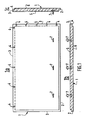
- Figure 1 we can see a particularly advantageous embodiment of a plate according to the present invention intended for the realization of a suspended ceiling.
- Figure 1a is a top view;
- Figures 1b and 1c are sectional views of a plate or slab according to the invention.
- the plate 1 according to the present invention has a substantially constant thickness.
- the plate may include ribs to improve the mechanical strength and / or release from the mold.
- the plate 1 according to the present invention comprises fittings as described in the French patent application, unpublished, No. 89 17340.
- the upper and lower faces of the plate 1 bear the references 5 and 6.
- Each plate comprises at minus a cornice or upper projection 3 and a lower projection 2.
- the projections 2 and 3 of the adjacent plates are intended to make a connection by forming a rebate.
- the upper and lower projections 3 and 2 are glued to each other with an adhesive having the desired qualities of insulation and / or firebreak.
- an adhesive having the desired qualities of insulation and / or firebreak.
- a plaster tile adhesive is used, for example that sold under the brand "FUSCO”.
- Means 4 prevent the thickness of the glue from making an excess thickness at the fittings.
- the means 4 are advantageously spacers making contact between two successive plates 1 while leaving a space for the adhesive. Even at the level of contact between two plates 1 at the level of the spacers 4 there is no excess thickness of adhesive.
- the presence of glue is avoided at the level of the spacers 4, for example by an adequate choice of the geometry of the spacers.
- the contact surface between the spacers 4 and the corresponding contact projection is substantially zero.
- spacers 4 are used which have a substantially triangular or trapezoidal profile, advantageously semi-cylindrical.
- the spacer 4 is disposed on the upper projections 3.
- account is taken of the habits existing on the site on which the adhesive is deposited on the plates 1 already in place. So there is less risk that the glue will dry on the spacers 4.
- the plates 1 comprising spacers on the lower projections or on the lower and upper projections do not depart from the scope of the present invention.
- the plates according to the present invention advantageously include projections 2 or 3 on all sides.
- these projections make it possible to better distribute the weight, and above all to form baffles improving the desired insulation at all of the plate connections.
- the plate 1 is rectangular.
- the upper projections 3 are formed on a large side and a small side allowing the normal progression of the installation according to the habits of the sites. It is understood that the use of plates having another shape, such as for example square, triangular or hexagonal does not depart from the scope of the present invention.
- the plate includes anchoring means 7.
- the anchoring means 7 are not, for example, metal parts placed in the upper face 5 of the plate 1 at the time of its production and whose ends protrude flat. On a building site, the anchoring means 7 are unfolded to allow them to be used for hanging the plates.
- the attachment means are made of a material which is not likely to be corroded, such as for example galvanized steel.
- the hooking means are regularly spaced along the length of the plate close to the side comprising a lower projection 2.
- the distribution is advantageously such that the longitudinal spacing between two successive anchoring means 7 in the laid slab is constant.
- the anchoring means 7 support the part of the plate 1 comprising the lower projection 2.
- the lower projection 2 supports the upper projection 3 of the following plate.
- the plates having anchoring means on more than one side do not depart from the scope of the present invention.
- the plates 1 according to the present invention are not exactly flat.
- the lower surface 6 intended for receiving the paint is perfectly flat, so we create flawless ceilings.
- the plates 1 according to the present invention can rest one on the other only by their ends. Contacts are avoided by local extra thicknesses 21 at the ends and / or by a profile of the slightly concave upper face 5. This face is not visible, the concavity is not annoying.
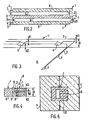
- FIG 3 we can see an example of arrangement of spacers 4 on the plate according to the present invention.
- the illustrated spacers 4 are of the semi-cylindrical type having the advantage of being easily achievable while being of great resistance.
- the spacers 4 have for example a width of 9 mm and a thickness d1 of 3 mm.
- the spacers 4 are for example 146 mm apart.
- the upper projection 3 has a thickness referenced d3.
- the distance between the spacers 4 and the lower edges of the plate 1 is equal to d2.
- d2 is also equal to the thickness of the lower projection 2 located at the other end of the plate (not shown in Figure 3).
- FIG. 4 there is illustrated a junction 8 of adjacent plates 1.
- the glue 9 can fill a space with a thickness equal to d1.
- the thickness of the plate D is equal to d1 + d2 + d3.
- the section in FIG. 4 does not pass through a spacer 4.
- FIG 5 one can see a suspended ceiling according to the present invention.
- the installation according to the present invention begins with the establishment of rules ensuring the support of the first plates that will be placed along the wall (not shown in the figure). We provide the necessary insulation between the wall and the first plate.
- the anchoring point 7 of the plate 1 is connected with a suspension means 14 to an anchoring point 13 of the ceiling 10.
- the support means 14 is for example constituted by a galvanized wire. It passes for example through an opening made in the anchoring means 7.
- a protective means 11 is for example made up of two plaster half-shells (or with the same materials as those of the plate).
- each half-shell 11 is filled with a binder 12, for example with plaster.
- the presence of the binder 12 prevents the descent of the plate 1 in the case where the suspension means 14 is not properly tensioned.
- the anchoring means 7 comprises means 15 increasing the lift of the anchoring means 7 in the binder 12.
- the means 15 comprise for example spikes, or on the contrary substantially flat horizontal surfaces.
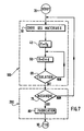
- FIG. 7 one can see a flowchart illustrating an example of a method for producing plates according to the present invention.
- the production method according to the present invention mainly comprises a set of steps 100 consisting in determining the constitution and the geometry to be used to obtain the desired insulation and a step 200 consisting in checking the technical and economic reliability of such a plate and ensuring its manufacture.
- the process according to the present invention begins in 20.
- the choice of materials used in the composition of the plate is made.
- plaster or fibers are always used, for example glass fibers.
- expanded materials it is particularly advantageous to add expanded perlite which is a volcanic rock.
- perlite sold by the company DICALITE ESPANOLA S.A. of Barcelona (Spain) is used.
- between 0.1 and 5 liters of perlite, typically 0.5 liters, are used for one kilogram of plaster.
- the thickness of the plate necessary to obtain the desired acoustic, thermal and / or fire insulation is determined. For example, in 40 we choose a thickness D equal to a minimum thickness D0. The minimum thickness is for example equal to 9 mm.
- the thickness is increased by an increment d, for example equal to 1 mm.
- step 100 it is checked that the plate recommended during step 100 (comprising steps 30 to 60) is feasible from the technical and economic point of view.
- the plate has a mechanical resistance necessary to support its own weight and that it can be suspended.
- gold checks whether such a plate is not prohibitively expensive, which would cause commercial failure. If not, go to 30 (to modify the composition of the plate).
- the plate comprising the materials chosen in step 30 with a thickness D chosen in the last step 50 is produced.
- the plate is advantageously produced by molding. It may be necessary to respect the order of introduction of the various components. If, for example, during step 30, it was decided to incorporate a wire mesh into the plate according to the present invention, to improve the fire resistance, this wire mesh will be introduced into the mold prior to the introduction of the others elements, including plaster.
- test steps 60 and 70 are carried out by actual tests or tests and / or by simulation, for example on a microcomputer in particular with commercial software.
- fire-resistant plates can be made which can resist fire for 2 hours, the thickness D of which is between 40 and 50 mm, using only plaster and fiberglass and the thickness of which is included between 20 and 30 mm for a plate further comprising perlite. It is pointed out that a plate comprising perlite is lighter, for example between 30 and 40%, for a given thickness.
- the plate 1 has ribs 22 of small thickness, for example equal to 3 mm, facilitating demolding.
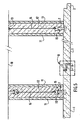
- the plate 1 of FIG. 8, of substantially rectangular shape has on one of its widths a projection or protuberance 23.
- the opposite width has a corresponding recess 25.
- FIG 8 the sections through the edges of the plate illustrating improved profiles for forming baffles, particularly effective in providing protection against flames.
- the section along arrow A of the projection 23 illustrates a lower projections 29 of small amplitude and an upper projection 31 of greater amplitude.
- the upper projection 31 rests on a lower projection 28 of the recess 25 illustrated in the section along the arrow A ′.
- the profile of the projection 23 corresponds to the profile of the recess 25, however leaving a space for the glue (the cut along A A ′ does not pass through a spacer).
- the recess 25 has an upper projection 27 of smaller amplitude than the lower projection 28.
- the ends 24 and 26 of width of the plate 1 do not have projections 31 and 28.
- the projections 29 and 27 remain , leaving a baffle delaying the propagation of the flames, as can be seen on the sections according to arrows D and D ′.
- the sections along C and C ′ of the lower projection 2 and the upper projection 3 show a profile similar to the recess 25 and the projection 23 respectively.
- the section along the arrow C ′ passes through a spacer 4.
- the plate 1 according to the present invention comprises a series 37 of anchoring means arranged near the lower projection 2 during the molding of the plate 1.
- These anchoring means are arranged in a folded position.
- the anchoring means necessary for the suspension of the plate are unfolded.
- a sheath can for example constitute such an obstacle.
- a series 37 of the anchoring means is further arranged parallel to the recess 25. The anchoring means will allow the installation of the false ceilings to be completed along a wall.
- a series 37 of the anchoring means is illustrated in FIG. 9. It comprises a succession of anchoring means 7 connected by a central strip 32.
- An anchoring means 7 comprises tongues 33 and 34, intended to penetrate approximately in half the thickness of the plate 1.
- the arrangement of an anchoring element 7 in its folded position is illustrated in FIG. 10.
- the anchoring means 7 is deployed orthogonally to the strip 32. During transport, the excess thickness of the strip 32 is masked by the ribs 22.
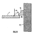
- a plate 1 placed along a wall 35.
- the plate is suspended by a suspension means 14 advantageously equipped with fire protection, not shown.
- On the wall 35 is fixed, for example by gluing, an element 36.
- the element 36 is for example made of plaster or staff.
- the plate 1 is glued with glue or a seal 39 to the element 36.
- a seal is used for gluing plaster sold under the brand "RUBSON".
- a slot 38 which, in addition to its decorative effect, plays the role of space for expansion of the plates 1 during a fire.
- the slot 38 participates in the fire barrier role played by the plates 1.
- the present invention applies to the production of insulating plates and / or firebreaks for producing partitions in buildings.
- the present invention applies mainly to the production of suspended ceilings or doubling, in particular for the production of ducts.
Landscapes
- Engineering & Computer Science (AREA)
- Architecture (AREA)
- Physics & Mathematics (AREA)
- Electromagnetism (AREA)
- Civil Engineering (AREA)
- Structural Engineering (AREA)
- Building Environments (AREA)
- Laminated Bodies (AREA)
Applications Claiming Priority (2)
| Application Number | Priority Date | Filing Date | Title |
|---|---|---|---|
| FR9005262 | 1990-04-25 | ||
| FR9005262A FR2661439A1 (fr) | 1990-04-25 | 1990-04-25 | Procede de realisation de plaques pour plafonds suspendus, plaques realisees selon le procede et procede de pose de plaques. |
Publications (1)
| Publication Number | Publication Date |
|---|---|
| EP0454583A1 true EP0454583A1 (de) | 1991-10-30 |
Family
ID=9396067
Family Applications (1)
| Application Number | Title | Priority Date | Filing Date |
|---|---|---|---|
| EP91401100A Withdrawn EP0454583A1 (de) | 1990-04-25 | 1991-04-25 | Verfahren zur Herstellung von Deckenplatten, nach dem Verfahren hergestellte Platten und Verfahren zur Aufstellung der Platten |
Country Status (3)
| Country | Link |
|---|---|
| EP (1) | EP0454583A1 (de) |
| ES (1) | ES2025983A6 (de) |
| FR (1) | FR2661439A1 (de) |
Cited By (1)
| Publication number | Priority date | Publication date | Assignee | Title |
|---|---|---|---|---|
| NL1006145C2 (nl) * | 1997-05-28 | 1998-12-01 | Rockwool Rockfon B V | Geluidsisolerende plaatstructuur. |
Citations (6)
| Publication number | Priority date | Publication date | Assignee | Title |
|---|---|---|---|---|
| CH312694A (fr) * | 1954-03-23 | 1956-02-29 | Ruga Arthur | Plafond suspendu préfabriqué |
| FR1483017A (fr) * | 1966-04-22 | 1967-06-02 | Perfectionnements aux joints d'assemblage, pour éléments de construction et autres | |
| FR1483910A (fr) * | 1966-04-26 | 1967-06-09 | Perfectionnements aux plaques préfabriquées pour construction de plafonds et autres | |
| FR1575529A (de) * | 1966-08-19 | 1969-07-25 | ||
| FR2201381A1 (de) * | 1972-09-29 | 1974-04-26 | Cavalleiro Pierre | |
| EP0127545A2 (de) * | 1983-05-27 | 1984-12-05 | Etablissements Roulot S.A. | Nebeneinander zusammenfügbare Modulelemente, insbesondere für die Herstellung durchgehender Wände |
Family Cites Families (1)
| Publication number | Priority date | Publication date | Assignee | Title |
|---|---|---|---|---|
| DE3008398A1 (de) * | 1980-03-05 | 1981-09-17 | Grünzweig + Hartmann und Glasfaser AG, 6700 Ludwigshafen | Feuerbestaendige unterdecke, fuer sich allein |
-
1990
- 1990-04-25 FR FR9005262A patent/FR2661439A1/fr not_active Withdrawn
- 1990-09-14 ES ES9002375A patent/ES2025983A6/es not_active Expired - Lifetime
-
1991
- 1991-04-25 EP EP91401100A patent/EP0454583A1/de not_active Withdrawn
Patent Citations (6)
| Publication number | Priority date | Publication date | Assignee | Title |
|---|---|---|---|---|
| CH312694A (fr) * | 1954-03-23 | 1956-02-29 | Ruga Arthur | Plafond suspendu préfabriqué |
| FR1483017A (fr) * | 1966-04-22 | 1967-06-02 | Perfectionnements aux joints d'assemblage, pour éléments de construction et autres | |
| FR1483910A (fr) * | 1966-04-26 | 1967-06-09 | Perfectionnements aux plaques préfabriquées pour construction de plafonds et autres | |
| FR1575529A (de) * | 1966-08-19 | 1969-07-25 | ||
| FR2201381A1 (de) * | 1972-09-29 | 1974-04-26 | Cavalleiro Pierre | |
| EP0127545A2 (de) * | 1983-05-27 | 1984-12-05 | Etablissements Roulot S.A. | Nebeneinander zusammenfügbare Modulelemente, insbesondere für die Herstellung durchgehender Wände |
Cited By (1)
| Publication number | Priority date | Publication date | Assignee | Title |
|---|---|---|---|---|
| NL1006145C2 (nl) * | 1997-05-28 | 1998-12-01 | Rockwool Rockfon B V | Geluidsisolerende plaatstructuur. |
Also Published As
| Publication number | Publication date |
|---|---|
| FR2661439A1 (fr) | 1991-10-31 |
| ES2025983A6 (es) | 1992-04-01 |
Similar Documents
| Publication | Publication Date | Title |
|---|---|---|
| CA2739695A1 (fr) | Panneau composite pour paroi et procede de fabrication | |
| EP2920377B1 (de) | Verfahren zum errichten eines gebäudes mit starker wärmedämmung und in diesem verfahren errichtetes gebäude | |
| EP0921242A2 (de) | Akustische Gebäudestruktur | |
| EP0014294A1 (de) | Vorgefertigtes Bauelement für Isolationszwecke | |
| EP2225426B1 (de) | System zur aussenisolierung von gebäuden | |
| FR2924138A1 (fr) | Systeme d'isolation de batiments par l'exterieur | |
| EP1771629B1 (de) | Flaches montage- und anordungselement aus einem oder mehreren elementen | |
| EP2479354A1 (de) | Modul das als thermische Trennung dient und mit einem Z-Profil ausgestattet ist | |
| EP0454583A1 (de) | Verfahren zur Herstellung von Deckenplatten, nach dem Verfahren hergestellte Platten und Verfahren zur Aufstellung der Platten | |
| FR2655675A1 (fr) | Panneau de cloisonnement isolant et coupe-feu. | |
| WO2016046496A1 (fr) | Batiment a isolation thermique amelioree, procédé de construction dudit bâtiment et agrafes conçues pour la mise en œuvre dudit procede | |
| EP2423402A2 (de) | Stark isoliertes Fertigteil | |
| FR2939817A1 (fr) | Bloc elementaire prefabrique pour la construction d'un mur a isolation exterieure | |
| EP0937857B1 (de) | Feuerbeständige Trennwand mit Verglasungselementen | |
| WO1996004437A1 (fr) | Plancher filant vitre coupe-feu 120 minutes | |
| EP2339085A1 (de) | Vorgefertigtes Element zum Bau von Gebäudeanbauten, und so erstellte Gebäudeanbauten | |
| FR2712012A1 (fr) | Revêtement de façade de mur. | |
| EP1528175B1 (de) | Verfahren zur Herstellung von Fassaden, Dächern oder Decken mit selbsttragenden feuerbeständigen Platten | |
| FR2745021A1 (fr) | Element modulaire composite de plancher et procede de fabrication d'un plancher | |
| EP0427596B1 (de) | Thermische und Schalisolierung, insbesondere für Decken von Kellern, Parkgaragen oder Kriechraum und Verfahren zu deren Anbringung | |
| FR2690940A1 (fr) | Système de construction à base de blocs autoporteurs légers de grande dimension en matière plastique expansée. | |
| FR2972011A1 (fr) | Construction a ossature bois comprenant des elements a base de carton et module de construction | |
| EP1775397A1 (de) | Isolationsschalung für Betonwandungen | |
| FR2745833A1 (fr) | Procede de fabrication de parois et produits obtenus | |
| FR2771763A1 (fr) | Structure acoustique de batiment |
Legal Events
| Date | Code | Title | Description |
|---|---|---|---|
| PUAI | Public reference made under article 153(3) epc to a published international application that has entered the european phase |
Free format text: ORIGINAL CODE: 0009012 |
|
| AK | Designated contracting states |
Kind code of ref document: A1 Designated state(s): BE CH DE ES FR GB IT LI |
|
| 17P | Request for examination filed |
Effective date: 19920415 |
|
| 17Q | First examination report despatched |
Effective date: 19921211 |
|
| STAA | Information on the status of an ep patent application or granted ep patent |
Free format text: STATUS: THE APPLICATION IS DEEMED TO BE WITHDRAWN |
|
| 18D | Application deemed to be withdrawn |
Effective date: 19930622 |