EP0454615B1 - Pince pour couper des clous, des fils ou d'autres articles chirurgicaux similaires - Google Patents
Pince pour couper des clous, des fils ou d'autres articles chirurgicaux similaires Download PDFInfo
- Publication number
- EP0454615B1 EP0454615B1 EP91710015A EP91710015A EP0454615B1 EP 0454615 B1 EP0454615 B1 EP 0454615B1 EP 91710015 A EP91710015 A EP 91710015A EP 91710015 A EP91710015 A EP 91710015A EP 0454615 B1 EP0454615 B1 EP 0454615B1
- Authority
- EP
- European Patent Office
- Prior art keywords
- cutting
- jaw
- forceps
- forcep
- forceps according
- Prior art date
- Legal status (The legal status is an assumption and is not a legal conclusion. Google has not performed a legal analysis and makes no representation as to the accuracy of the status listed.)
- Expired - Lifetime
Links
Images

Classifications
-
- A—HUMAN NECESSITIES
- A61—MEDICAL OR VETERINARY SCIENCE; HYGIENE
- A61B—DIAGNOSIS; SURGERY; IDENTIFICATION
- A61B17/00—Surgical instruments, devices or methods
- A61B17/56—Surgical instruments or methods for treatment of bones or joints; Devices specially adapted therefor
- A61B17/58—Surgical instruments or methods for treatment of bones or joints; Devices specially adapted therefor for osteosynthesis, e.g. bone plates, screws or setting implements
- A61B17/88—Osteosynthesis instruments; Methods or means for implanting or extracting internal or external fixation devices
- A61B17/8863—Apparatus for shaping or cutting osteosynthesis equipment by medical personnel
-
- B—PERFORMING OPERATIONS; TRANSPORTING
- B26—HAND CUTTING TOOLS; CUTTING; SEVERING
- B26B—HAND-HELD CUTTING TOOLS NOT OTHERWISE PROVIDED FOR
- B26B17/00—Hand cutting tools, i.e. with the cutting action actuated by muscle power with two jaws which come into abutting contact
- B26B17/02—Hand cutting tools, i.e. with the cutting action actuated by muscle power with two jaws which come into abutting contact with jaws operated indirectly by the handles, e.g. through cams or toggle levers
Definitions
- the invention relates to pliers - in particular pliers for cutting surgical nails, wires or the like - according to the preamble of the independent claim.
- Pliers with a cutting mouth delimited by two cutting edges at the head end are required in particular in orthopedics for cutting wires, nails or screw elements. Preventing chips or similar material particles during the separation process to avoid infections is a hygienic necessity.
- FR-A-495 124 discloses a pruning shears, punching or punching pliers and especially for tin cans a tool with the generic features, in which a roller at the free end of the swivel jaw cooperates with a curved guide edge of a link piece which is assigned to a gear . Its toothing interacts with a pawl of the articulated movable pliers arm and is moved by the latter about a hinge pin connecting the two pliers arms.
- the inventor has set itself the goal of designing pliers of the type described at the outset in such a way that the user can cut material strands or profiles with as little cutting as possible, even with little effort, with one hand; the power of the operator should be able to be used optimally regardless of the material properties and strand thickness.
- the curve piece is provided on the second pliers arm, and the curvature of this curve piece increases towards the cutting mouth. Thanks to this provision, it is now possible to even out the force arriving at the cutting device - for example a blade insert - by the curvature of the curve piece; for this purpose, it has also proven to be advantageous to make the curve piece interchangeable as a backdrop for the roller on the pliers, so that pliers can be used for different materials or areas of application.
- the curve piece is advantageously part of a guide section of the second gun arm, and the path of movement of the guide section is arranged at a distance from the joint of the gun arms.
- the guide section it has proven to be advantageous to design the guide section as part of a triangular-shaped head part of the second gun arm in side view, a triangle side extending the handle end of the gun arm having the curve piece and the two other triangle sides starting from the end of the curve piece or from the handle end and starting at Hit the joint of the gun arms.
- a straight line connecting the joint between the swivel jaw and the tong arm to the roller axis should preferably enclose an angle with a straight line through this roller axis and the joint of the tong arms which is a little larger than 90 ° and in particular between 96 ° and 104 °.
- a stop surface has proven to be favorable, which is offered by a stop nose running approximately in a vertical of the guide section through the joint of the pliers arms.
- the distance of the joint between the one arm of the pliers and the swivel jaw and the pliers face is shorter than the distance of this joint from the roller at the end of the swivel jaw.
- the cutting jaw can have at least two zones of different cutting edge spacing, at least one of the cutting edges being divided into cutting edge sections by a step surface running transversely to the pliers axis, of which the further end of the free end of the cutting jaw - preferred - in the closed state of the pliers of the opposite cutting edge.
- a pair of cutting edges does not have to travel through the entire wire cross-section during the cutting process; the - advantageously provided at the free end of the cutting mouth - cutting pair with the greatest distance between their cutting edges notches the wire, which is then pushed towards the next cutting stage; the cutting edges of which are assigned to one another and are able to penetrate further into the material with little effort.
- the number of cutting stages depends on the nature of the material or wire to be cut or the like. dependent, their distances from one another, which are set up transversely to the longitudinal axis of the pliers, are preferably of the same size or somewhat increasing at the deepest point of the mouth.
- the cutting edges of one or the other pair of cutting edges - in the closed position of the cutting jaw - may even run at an angle to the longitudinal axis of the mouth in order to produce completely parallel cutting grooves at this cutting stage.
- each cutting jaw can have at least one run-up surface which, when the cutting jaw is closed, rests against a run-up surface of the other cutting jaw; thanks to this requirement, the cutting edges are effectively avoided.
- the run-up surface of the cutting jaw is preferably aligned with its cutting edge. It has also proven to be advantageous if the cutting edge runs between two running surfaces of the cutting jaw or the running surfaces of the cutting jaw are provided on two horn pieces and these are connected by a cutting edge; this configuration increases the stability of the cutting edge or the cutting edge.
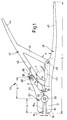
- a cutting insert 15 offered by it is articulated by a head joint 20 with a swivel jaw 22 provided with the other cutting insert 15 a .
- This is kidney-like in side view and carries a roller 28 on its free jaw end 24 , which is remote from the cutting insert 15 a, on a bolt-like axis 26.
- the distance a of the head joint 20 from the pliers face 13 is shorter than its distance b from the axis pin 26 of the roller 28.
- the swing jaw 22 includes - from the saw to at a distance i of the cutting inserts 15, 15 a open cutting mouth 14 HER - behind the head joint 20 with the - here of two side plates 19 of a U- Profile section formed - pliers arm 18 an acute angle w.
- the jaw contour 30 delimiting this angle w is followed at an obtuse angle t by a jaw edge 31 which, with an outer edge 32 of the pivoting jaw 22 which is slightly curved inwards, determines that free jaw end 24.
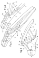
- the roller 28 rests on a stop lug 38 of a pressure arm 40 which is pivotally assigned to the pliers arm 18 and which does not exist in the embodiments of FIGS. 3 to 5, which roller-side has a guide section 42 and then a handle end 44 protruding rearward therefrom having.
- the latter with a handle end 45 of the pliers arm 18, represents the pliers handle, the partners 44, 45 of which during a separation process - that is to say during the transition from the rest position according to FIG. 1 to the separation position according to FIG. 2 - become smaller as the pincer or closing angle becomes smaller z approach each other.
- the guide section 42 of the pressure arm 40 forms an integral triangle with an inclined web 41 and an end web 43.
- Inclined web 41 and end web 43 meet at a bearing point penetrated by a hinge pin 46; this hinge pin 46 connects the pressure arm 40 with the pliers arm 18 so that it limits the pliers angle z with the inclined web 41.
- Fig. 1 shows that a connecting line E of the head joint 20 and roller axis 26 includes an angle n with a connecting line F, which is greater than 90 ° by an acute supplementary angle u of about 10 °.
- the cutting inserts 15, 15 a are moved by an eccentric system, which allows the aforementioned equalization of the force.
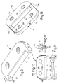
- FIG. 7 shows two cutting jaws 16, 16 a in pressure jaws 21, 21 a .
- Both cutting jaws 16, 16 a with a length f of approximately 22 mm and a height h of approximately 2.2 mm are fixed in correspondingly shaped recesses 52 in their respective pressure cheeks 21, 21 a, specifically by means of screws, not shown, which holes 54 of the cutting jaws 16 , 16 a pass through and are fixed in a stop bottom 53 of the recess 52.
- Sidewalls 56 of the generally rectangular ones inclined at an acute angle e Cutting jaw 16 merges into a rounded back 58, the surface of which in turn is slightly inclined.
- the side walls 56 each end on a run-up surface 60, the width g of which corresponds approximately to its height h.
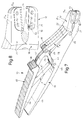
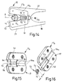
- Fig. 14 illustrates a surgical pliers 10 a , the pressure cheeks 21, 21 a - and thus their cutting cheeks 17, 17 a - can be pivoted relative to each other about a structural pivot point 70.
- the cutting jaws 17, 17 a are to form extending transversely to the forceps longitudinal axis A step surfaces 70 several times - in the selected embodiment even - graded, that is produced here between the edges 64 and 64 h two cutting jaw portions 14, 14 h.
- Their starting from the pliers end 13 is used to cut a wire of diameter d recognizable at 72 to produce a pair of notches 74 of the slightly decreasing distance c; then the wire 72 is shifted to the next jaw stage 14 h in order to be cut 64 h between the cutting edges which are closer together.
- the step-shaped cutting jaw design described enables a cutting through of larger diameters of, for example, 5 mm in two cutting stages, wherein in each of the pair of cutting edges 64 and 64 h only part of the cutting path d is active, the dimension of which is determined by the distance r between the adjacent cutting edges 64 and 64 h is determined, which corresponds to approximately half the dimension d in FIG. 14.
- the cutting edges of the front cutting jaw section 14 are somewhat inclined to the longitudinal axis A of the pliers - as the cutting jaw longitudinal axis - in such a way that they are slightly closer to one another at the free end of section 14 than in the inside of the cutting jaw; it is achieved in that the notches 74 thus produced have notches deepest or notch bottoms parallel to one another.
Landscapes
- Health & Medical Sciences (AREA)
- Life Sciences & Earth Sciences (AREA)
- Orthopedic Medicine & Surgery (AREA)
- Engineering & Computer Science (AREA)
- Surgery (AREA)
- Biomedical Technology (AREA)
- Animal Behavior & Ethology (AREA)
- Mechanical Engineering (AREA)
- Forests & Forestry (AREA)
- Heart & Thoracic Surgery (AREA)
- Medical Informatics (AREA)
- Molecular Biology (AREA)
- Nuclear Medicine, Radiotherapy & Molecular Imaging (AREA)
- General Health & Medical Sciences (AREA)
- Public Health (AREA)
- Veterinary Medicine (AREA)
- Scissors And Nippers (AREA)
- Surgical Instruments (AREA)
- Gripping Jigs, Holding Jigs, And Positioning Jigs (AREA)
Claims (14)
- Pince, en particulier pour couper des clous et fils chirurgicaux ou similaires, comportant, sur l'extrémité de tête de la pince, une bouche de coupe (14), qui est limitée par deux dispositifs de coupe (15, 15a) et qui présente, à l'autre extrémité, deux extrémités de manche (44, 45) de bras de pince (18,40) articulés entre eux, les extrémités de manche pouvant, contre une force de rappel, être réunies dans une position de coupe des dispositifs de coupe, et un des dispositifs de coupe (15a) étant prévu au niveau d'une mâchoire pivotante (22) qui est articulée sur un premier bras de pince (18) portant l'autre dispositif de coupe (15) et qui appuie, par son extrémité libre (24), sur une pièce courbe (42a),
caractérisée en ce que
la pièce courbe (42a) est prévue sur le second bras de pince (40) et en ce que la courbure de la pièce courbe (42a) augmente quand on se rapproche de la bouche de coupe (14). - Pince selon la revendication 1, caractérisée en ce que, à titre de limitation de course destinée à l'extrémité libre (24) de la mâchoire pivotante (22) ou à un galet (28) connu en lui-même sur la mâchoire pivotante (22), on prévoit une surface de butée (39) à l'extrémité de la pièce courbe (42a) qui est touchée par cette extrémité ou ce galet.
- Pince selon la revendication 1 ou 2, caractérisée en ce que la pièce courbe (42a) fait partie d'un segment de guidage (42) du second bras de pince (40) et en ce que le chemin de déplacement du segment de guidage est disposé à l'écart de l'articulation (46) des bras de pince (18, 40).
- Pince selon la revendication 2 ou 3, caractérisée en ce que la surface de butée (39) est constituée d'un bec de butée (38) qui est disposé à peu près dans une perpendiculaire du segment de guidage (42) à travers l'articulation (46) des bras de pince (18, 40).
- Pince selon la revendication 3 ou 4, caractérisée en ce que le segment de guidage (42) fait partie d'une pièce de tête (41 à 43), de forme triangulaire en vue de côté, du second bras de pince (40), où un côté de triangle prolongeant l'extrémité de manche (44) du bras de pince (40) présente la pièce courbe (42a) et éventuellement la surface de butée (39) tandis que les deux autres côtés du triangle (41, 43) partent de l'extrémité de la pièce courbe (42a) et de l'extrémité de manche (44) et se rencontrent au niveau de l'articulation (46) des bras de pince (18, 40).
- Pince selon l'une des revendications 2 à 4, caractérisée en ce qu'une droite (E) reliant l'articulation (20) entre la mâchoire pivotante (22) et le bras de pince (18) à l'axe de galet (26) forme, avec une droite (F) traversant cet axe de galet ainsi que l'articulation (46) des bras de pince (18, 40), un angle (n) qui est légèrement supérieur à 90°, en particulier un angle (n) compris entre 96° et 104°.
- Pince selon au moins l'une des revendications 1 à 5, caractérisée en ce que l'écart (a) de l'articulation (20) entre un bras de pince (18) et la mâchoire pivotante (22) ainsi que la face de pince (13) est plus court que l'écart (b) de cette articulation par rapport au galet (28) et/ou en ce que la pièce courbe (42a) sur le bras de pince (40) est disposée de façon à pouvoir être remplacée.
- Pince selon au moins l'une des revendications 1 à 7, caractérisée en ce que la bouche de coupe (14) présente au moins deux zones (14, 14a) présentant un écart de tranchant différent, au moins un des tranchants étant divisé en segments de tranchant (64, 64h) par une surface en gradins (70) oblique par rapport à l'axe longitudinal de pince (A), segments de coupe dont celui qui est le plus éloigné de l'extrémité libre (13) de la bouche de coupe est de préférence exposé au tranchant opposé (64, 64h) lorsque la pince (10a) est fermée.
- Pince selon au moins l'une des revendications 1 à 7, caractérisée en ce que l'axe longitudinal de pince (A) forme une droite de symétrie pour les tranchants (15, 15a, 64, 64h).
- Pince selon la revendication 8 ou 9, caractérisée par deux segments de tranchant (64, 64a) ainsi que par deux surfaces en gradins (70) quiaffleurent l'une avec l'autre et dont la hauteur (r) correspond à chaque fois à environ un quart de la longueur (d) d'une coupe effectuée dans un fil (72) ou élément similaire, les longueurs axiales des segments de tranchant (64, 64h) étant éventuellement à peu près égales.
- Pince selon au moins l'une des revendications 1 à 10, caractérisée en ce que chaque mâchoire de coupe (16, 16a) présente au moins une surface ascendante (60) qui, lorsque la bouche de coupe (14) est fermée, appuie contre une surface ascendants de l'autre mâchoire de coupe (16a, 16), la surface ascendante de la mâchoire de coupe affleurant éventuellement avec son arête de coupe (65).
- Pince selon la revendication 11, caractérisée en ce que l'arête de coupe (65) s'étend entre deux surfaces ascendantes (60) de la mâchoire de coupe (16, 16a) et/ou en ce que les surfaces ascendantes (60) de la mâchoire de coupe (16, 16a) sont prévues sur deux pièces en corne (62) et que celles-ci sont reliées par un tranchant (64).
- Pince selon au moins l'une des revendications 1 à 12, caractérisée en ce que la mâchoire de coupe (15, 16, 17) est maintenue, de façon amovible, dans une mâchoire de pression (21, 21a) et/ou en ce que la mâchoire de coupe appuie contre un fond de butée (53) d'un évidement (52) d'une mâchoire de pression (21, 21a).
- Pince selon au moins l'une des revendications 1 à 13, caractérisée en ce que les arêtes de coupe (65) d'au moins une des paires d'arêtes de coupe sont légèrement inclinées par rapport à l'axe longitudinal du segment de bouche de coupe (14) et sont, à l'extrémité de segment de bouche de coupe proche de l'extrémité libre de la pince, plus rapprochées l'une de l'autre que sur l'autre extrémité .
Applications Claiming Priority (2)
| Application Number | Priority Date | Filing Date | Title |
|---|---|---|---|
| DE9004793U DE9004793U1 (de) | 1990-04-27 | 1990-04-27 | Zange zum Schneiden chirurgischer Nägel, Drähte od.dgl. |
| DE9004793U | 1990-04-27 |
Publications (2)
| Publication Number | Publication Date |
|---|---|
| EP0454615A1 EP0454615A1 (fr) | 1991-10-30 |
| EP0454615B1 true EP0454615B1 (fr) | 1994-12-14 |
Family
ID=6853280
Family Applications (1)
| Application Number | Title | Priority Date | Filing Date |
|---|---|---|---|
| EP91710015A Expired - Lifetime EP0454615B1 (fr) | 1990-04-27 | 1991-04-26 | Pince pour couper des clous, des fils ou d'autres articles chirurgicaux similaires |
Country Status (4)
| Country | Link |
|---|---|
| US (1) | US5187869A (fr) |
| EP (1) | EP0454615B1 (fr) |
| AT (1) | ATE115383T1 (fr) |
| DE (2) | DE9004793U1 (fr) |
Families Citing this family (19)
| Publication number | Priority date | Publication date | Assignee | Title |
|---|---|---|---|---|
| DE4308319C1 (de) * | 1993-03-16 | 1994-06-01 | Aesculap Ag | Ablängzange für eine bandförmige Knochenplatte |
| US6085425A (en) * | 1996-07-09 | 2000-07-11 | Kmedic Inc. | Surgical cutter |
| US6725546B1 (en) * | 1999-08-05 | 2004-04-27 | Alterra Holdings Corporation | Hardened insert for cutting tools |
| DE20018390U1 (de) | 2000-10-27 | 2001-01-18 | Wenzler Medizintechnik GmbH, 78665 Frittlingen | Schneidzange |
| FR2822095B1 (fr) * | 2001-03-19 | 2003-07-18 | Arno Ind | Outil a branches articulees avec regulation de l'effort resistant. |
| DE20207785U1 (de) * | 2002-05-17 | 2003-09-25 | GEOMED Medizin-Technik GmbH & Co., 78532 Tuttlingen | Chirurgische Zange |
| US7346987B2 (en) * | 2002-09-27 | 2008-03-25 | Electroline Corporation | Cutting tool with work piece feed mechanism |
| US6971179B2 (en) * | 2002-09-27 | 2005-12-06 | Electroline Corporation | Cutting tool |
| DE10313827A1 (de) * | 2003-03-21 | 2004-09-30 | REMS-WERK Christian Föll und Söhne GmbH & Co. | Trennvorrichtung für Werkstücke, wie Stangen, Bolzen und dergleichen, insbesondere für Gewindestangen |
| US7530170B2 (en) * | 2005-07-19 | 2009-05-12 | Shackelford Richard A | Toenail clipper |
| JP2008030150A (ja) * | 2006-07-28 | 2008-02-14 | Mcc Corp | 棒鋼切断工具 |
| USD639510S1 (en) * | 2009-12-30 | 2011-06-07 | Perscitus Innovations, LLC | Nail trimmer—center lever |
| USD639509S1 (en) * | 2009-12-30 | 2011-06-07 | Perscitus Innovations, LLC | Nail trimmer-rounded |
| CN201907074U (zh) * | 2010-12-27 | 2011-07-27 | 润联(天津)五金工具有限公司 | 具有偏置钳口的卡压工具 |
| DE102011001013A1 (de) | 2011-03-02 | 2012-09-06 | Alexander Merz | Zange zum Schneiden von Werkstücken |
| US20170340373A1 (en) * | 2015-04-30 | 2017-11-30 | Zhengzhou Zezheng Technical Services Ltd. | Kirschner wire bending device |
| GB2552380A (en) * | 2016-07-22 | 2018-01-24 | Stanley Black & Decker Mea Fze | A hand tool |
| US20230061887A1 (en) * | 2021-08-27 | 2023-03-02 | ln'Tech Medical SAS | Rod cutter |
| US20240197379A1 (en) * | 2022-12-14 | 2024-06-20 | Sg, Llc | In situ rod cutters |
Family Cites Families (21)
| Publication number | Priority date | Publication date | Assignee | Title |
|---|---|---|---|---|
| FR325743A (fr) * | 1902-04-11 | 1903-05-06 | Marliave H De | Système de commande pour ciseaux, pinces, sécateurs |
| FR495124A (fr) * | 1917-09-14 | 1919-09-30 | Leon Dicop | Commande à encliquetage pour machoires de cisaille, sécateur, découpoir, pince, poinconneuse et outils analogues |
| US1435131A (en) * | 1921-04-13 | 1922-11-07 | John N Jacobson | Pliers |
| CH253352A (fr) * | 1944-05-12 | 1948-02-29 | Barthuel Roger Pierre | Cisaille pour le découpage des plâtres chirurgicaux en vue du déplâtrage. |
| US2556367A (en) * | 1948-02-10 | 1951-06-12 | Fiedler John | Device for cutting hard materials |
| US2647312A (en) * | 1949-05-12 | 1953-08-04 | Elmer Brandell | Hand tool |
| US2619138A (en) * | 1949-10-07 | 1952-11-25 | Lee Marler Herod | Straight beam adjustable jaw cam clamp |
| US2602993A (en) * | 1950-05-29 | 1952-07-15 | Armstrong Wayne | Can cutter |
| GB738298A (en) * | 1952-11-05 | 1955-10-12 | Danite Hard Metals Ltd | Wire cutter |
| US2745177A (en) * | 1955-06-27 | 1956-05-15 | Kortick Morris | Cutting tool |
| US2948962A (en) * | 1958-12-24 | 1960-08-16 | Champion De Arment Tool Compan | Pliers |
| US3182485A (en) * | 1962-12-31 | 1965-05-11 | Burndy Corp | Compression tool |
| AT277641B (de) * | 1968-05-15 | 1969-12-29 | Karl Seefried | Schere, insbesondere für Gartenarbeiten |
| US3772783A (en) * | 1972-03-28 | 1973-11-20 | M Averitt | Hand clipper |
| DE2216543A1 (de) * | 1972-04-06 | 1973-10-11 | Ruediger Ahrends | Zange |
| US3902206A (en) * | 1973-09-20 | 1975-09-02 | Joseph H Naquin | Insulation-removing pliers |
| US4058893A (en) * | 1976-06-25 | 1977-11-22 | Boyajian Alfred | Bolt cutter |
| US4141141A (en) * | 1977-09-23 | 1979-02-27 | Ideal Industire, Inc. | Wire cutter |
| US4599795A (en) * | 1983-06-11 | 1986-07-15 | Mcc Corporation | Cutting tool |
| DE3743605A1 (de) * | 1987-12-22 | 1989-07-06 | Delma Elektro Med App | Chirurgische zange |
| US4870965A (en) * | 1988-03-04 | 1989-10-03 | Jahanger Mohammed S | Umbilical cord cutting and clamping device |
-
1990
- 1990-04-27 DE DE9004793U patent/DE9004793U1/de not_active Expired - Lifetime
-
1991
- 1991-04-25 US US07/691,548 patent/US5187869A/en not_active Expired - Fee Related
- 1991-04-26 EP EP91710015A patent/EP0454615B1/fr not_active Expired - Lifetime
- 1991-04-26 AT AT91710015T patent/ATE115383T1/de active
- 1991-04-26 DE DE59103841T patent/DE59103841D1/de not_active Expired - Fee Related
Also Published As
| Publication number | Publication date |
|---|---|
| DE59103841D1 (de) | 1995-01-26 |
| US5187869A (en) | 1993-02-23 |
| ATE115383T1 (de) | 1994-12-15 |
| DE9004793U1 (de) | 1991-01-03 |
| EP0454615A1 (fr) | 1991-10-30 |
Similar Documents
| Publication | Publication Date | Title |
|---|---|---|
| EP0454615B1 (fr) | Pince pour couper des clous, des fils ou d'autres articles chirurgicaux similaires | |
| DE2653840C3 (fr) | ||
| EP0228032B1 (fr) | Outil à main du type pince | |
| EP4311627B1 (fr) | Mâchoires de pressage ainsi que pince de pressage avec deux mâchoires de serrage | |
| EP2709804B1 (fr) | Pince | |
| EP3718184B1 (fr) | Mâchoires de serrage pour une pince à dénuder et pince à dénuder | |
| EP0331927B1 (fr) | Pince coupante | |
| EP3718186A1 (fr) | Pince à dénuder | |
| WO2019207054A1 (fr) | Pince | |
| DE10192090B4 (de) | Handbetätigtes Drahtschneidewerkzeug sowie Mehrzweckwerkzeug mit einem derartigen Drahtschneidewerkzeug | |
| EP2257411B1 (fr) | Dispositif pour le positionnement ou la manipulation d objets | |
| EP4104263B1 (fr) | Outil de coupe de type pince | |
| EP2512744A1 (fr) | Pince | |
| DE202006009273U1 (de) | Schneidbackenpaar | |
| EP0678944A2 (fr) | Outil pince pour torsader partiellement un embout de câble dénudé multibrin, come âme d'un conducteur isolé | |
| DE19949511B4 (de) | Hebelübersetztes Schneidwerkzeug | |
| EP3568890B1 (fr) | Pince à dénuder | |
| WO2018115171A2 (fr) | Outil à main doté d'une fonction cliquet | |
| WO2019207034A1 (fr) | Pince | |
| DE4424493C2 (de) | Zangenartiges Werkzeug zum formschlüssigen Verbinden von Blechteilen | |
| DE4301764A1 (de) | Mehrzweckwerkzeug | |
| DE9105152U1 (de) | Zange zum Schneiden chirurgischer Nägel, Drähte o.dgl. | |
| DE19506457A1 (de) | Kabelschneider, insbesondere Kabelschere | |
| EP1045499A1 (fr) | Pince | |
| DE10358553B3 (de) | Zange, insbesondere Ösenzange |
Legal Events
| Date | Code | Title | Description |
|---|---|---|---|
| PUAI | Public reference made under article 153(3) epc to a published international application that has entered the european phase |
Free format text: ORIGINAL CODE: 0009012 |
|
| AK | Designated contracting states |
Kind code of ref document: A1 Designated state(s): AT BE CH DE DK ES FR GB GR IT LI LU NL SE |
|
| 17P | Request for examination filed |
Effective date: 19911028 |
|
| RBV | Designated contracting states (corrected) |
Designated state(s): AT CH DE ES FR GB IT LI NL SE |
|
| 17Q | First examination report despatched |
Effective date: 19930714 |
|
| GRAA | (expected) grant |
Free format text: ORIGINAL CODE: 0009210 |
|
| AK | Designated contracting states |
Kind code of ref document: B1 Designated state(s): AT CH DE ES FR GB IT LI NL SE |
|
| PG25 | Lapsed in a contracting state [announced via postgrant information from national office to epo] |
Ref country code: IT Free format text: LAPSE BECAUSE OF FAILURE TO SUBMIT A TRANSLATION OF THE DESCRIPTION OR TO PAY THE FEE WITHIN THE PRE;WARNING: LAPSES OF ITALIAN PATENTS WITH EFFECTIVE DATE BEFORE 2007 MAY HAVE OCCURRED AT ANY TIME BEFORE 2007. THE CORRECT EFFECTIVE DATE MAY BE DIFFERENT FROM THE ONE RECORDED.SCRIBED TIME-LIMIT Effective date: 19941214 Ref country code: NL Effective date: 19941214 Ref country code: ES Free format text: THE PATENT HAS BEEN ANNULLED BY A DECISION OF A NATIONAL AUTHORITY Effective date: 19941214 Ref country code: FR Effective date: 19941214 Ref country code: GB Effective date: 19941214 |
|
| REF | Corresponds to: |
Ref document number: 115383 Country of ref document: AT Date of ref document: 19941215 Kind code of ref document: T |
|
| REF | Corresponds to: |
Ref document number: 59103841 Country of ref document: DE Date of ref document: 19950126 |
|
| PG25 | Lapsed in a contracting state [announced via postgrant information from national office to epo] |
Ref country code: SE Effective date: 19950314 |
|
| PG25 | Lapsed in a contracting state [announced via postgrant information from national office to epo] |
Ref country code: AT Effective date: 19950426 |
|
| PG25 | Lapsed in a contracting state [announced via postgrant information from national office to epo] |
Ref country code: CH Effective date: 19950430 Ref country code: LI Effective date: 19950430 |
|
| EN | Fr: translation not filed | ||
| NLV1 | Nl: lapsed or annulled due to failure to fulfill the requirements of art. 29p and 29m of the patents act | ||
| GBV | Gb: ep patent (uk) treated as always having been void in accordance with gb section 77(7)/1977 [no translation filed] |
Effective date: 19941214 |
|
| PLBE | No opposition filed within time limit |
Free format text: ORIGINAL CODE: 0009261 |
|
| 26N | No opposition filed | ||
| REG | Reference to a national code |
Ref country code: CH Ref legal event code: PL |
|
| PGFP | Annual fee paid to national office [announced via postgrant information from national office to epo] |
Ref country code: DE Payment date: 20050520 Year of fee payment: 15 |
|
| PG25 | Lapsed in a contracting state [announced via postgrant information from national office to epo] |
Ref country code: DE Free format text: LAPSE BECAUSE OF NON-PAYMENT OF DUE FEES Effective date: 20061101 |