EP0454628A1 - Geräuschabschirmung für Spindelventile mit Keramikdichtscheiben - Google Patents
Geräuschabschirmung für Spindelventile mit Keramikdichtscheiben Download PDFInfo
- Publication number
- EP0454628A1 EP0454628A1 EP91830102A EP91830102A EP0454628A1 EP 0454628 A1 EP0454628 A1 EP 0454628A1 EP 91830102 A EP91830102 A EP 91830102A EP 91830102 A EP91830102 A EP 91830102A EP 0454628 A1 EP0454628 A1 EP 0454628A1
- Authority
- EP
- European Patent Office
- Prior art keywords
- disk
- baffle
- antinoise
- entrainer
- water
- Prior art date
- Legal status (The legal status is an assumption and is not a legal conclusion. Google has not performed a legal analysis and makes no representation as to the accuracy of the status listed.)
- Granted
Links
- 239000000919 ceramic Substances 0.000 title claims abstract description 10
- XLYOFNOQVPJJNP-UHFFFAOYSA-N water Substances O XLYOFNOQVPJJNP-UHFFFAOYSA-N 0.000 claims abstract description 22
- 230000000284 resting effect Effects 0.000 claims abstract 2
- 239000000853 adhesive Substances 0.000 description 2
- 230000001070 adhesive effect Effects 0.000 description 2
- 238000000034 method Methods 0.000 description 2
- 230000004888 barrier function Effects 0.000 description 1
- 238000005452 bending Methods 0.000 description 1
- 239000002184 metal Substances 0.000 description 1
- 239000002245 particle Substances 0.000 description 1
Images
Classifications
-
- F—MECHANICAL ENGINEERING; LIGHTING; HEATING; WEAPONS; BLASTING
- F16—ENGINEERING ELEMENTS AND UNITS; GENERAL MEASURES FOR PRODUCING AND MAINTAINING EFFECTIVE FUNCTIONING OF MACHINES OR INSTALLATIONS; THERMAL INSULATION IN GENERAL
- F16K—VALVES; TAPS; COCKS; ACTUATING-FLOATS; DEVICES FOR VENTING OR AERATING
- F16K3/00—Gate valves or sliding valves, i.e. cut-off apparatus with closing members having a sliding movement along the seat for opening and closing
- F16K3/02—Gate valves or sliding valves, i.e. cut-off apparatus with closing members having a sliding movement along the seat for opening and closing with flat sealing faces; Packings therefor
- F16K3/04—Gate valves or sliding valves, i.e. cut-off apparatus with closing members having a sliding movement along the seat for opening and closing with flat sealing faces; Packings therefor with pivoted closure members
- F16K3/06—Gate valves or sliding valves, i.e. cut-off apparatus with closing members having a sliding movement along the seat for opening and closing with flat sealing faces; Packings therefor with pivoted closure members in the form of closure plates arranged between supply and discharge passages
- F16K3/08—Gate valves or sliding valves, i.e. cut-off apparatus with closing members having a sliding movement along the seat for opening and closing with flat sealing faces; Packings therefor with pivoted closure members in the form of closure plates arranged between supply and discharge passages with circular plates rotatable around their centres
-
- F—MECHANICAL ENGINEERING; LIGHTING; HEATING; WEAPONS; BLASTING
- F16—ENGINEERING ELEMENTS AND UNITS; GENERAL MEASURES FOR PRODUCING AND MAINTAINING EFFECTIVE FUNCTIONING OF MACHINES OR INSTALLATIONS; THERMAL INSULATION IN GENERAL
- F16K—VALVES; TAPS; COCKS; ACTUATING-FLOATS; DEVICES FOR VENTING OR AERATING
- F16K47/00—Means in valves for absorbing fluid energy
- F16K47/02—Means in valves for absorbing fluid energy for preventing water-hammer or noise
- F16K47/026—Means in valves for absorbing fluid energy for preventing water-hammer or noise preventing noise in a single handle mixing valve
-
- Y—GENERAL TAGGING OF NEW TECHNOLOGICAL DEVELOPMENTS; GENERAL TAGGING OF CROSS-SECTIONAL TECHNOLOGIES SPANNING OVER SEVERAL SECTIONS OF THE IPC; TECHNICAL SUBJECTS COVERED BY FORMER USPC CROSS-REFERENCE ART COLLECTIONS [XRACs] AND DIGESTS
- Y10—TECHNICAL SUBJECTS COVERED BY FORMER USPC
- Y10T—TECHNICAL SUBJECTS COVERED BY FORMER US CLASSIFICATION
- Y10T137/00—Fluid handling
- Y10T137/794—With means for separating solid material from the fluid
- Y10T137/8122—Planar strainer normal to flow path
-
- Y—GENERAL TAGGING OF NEW TECHNOLOGICAL DEVELOPMENTS; GENERAL TAGGING OF CROSS-SECTIONAL TECHNOLOGIES SPANNING OVER SEVERAL SECTIONS OF THE IPC; TECHNICAL SUBJECTS COVERED BY FORMER USPC CROSS-REFERENCE ART COLLECTIONS [XRACs] AND DIGESTS
- Y10—TECHNICAL SUBJECTS COVERED BY FORMER USPC
- Y10T—TECHNICAL SUBJECTS COVERED BY FORMER US CLASSIFICATION
- Y10T137/00—Fluid handling
- Y10T137/8593—Systems
- Y10T137/86493—Multi-way valve unit
- Y10T137/86815—Multiple inlet with single outlet
Definitions
- the present invention generally relates to screw type valves with ceramic disk seals for the delivery of hot or cold water from a tap for sanitary systems, and more particular to an antinoise baffle for said valves.
- valves comprise an annular head gasket, a fixed ceramic disk with at least one water inlet hole, a movable ceramic disk that rests against and rotates on the fixed one with at least one hole or slot which is positionable in correspondence to or away from the one of the fixed disk when the movable disk is rotated a quarter or a half turn.
- the gasket and disks are placed inside a hollow cylinder body designed to be screwed inside a tap in line with a water pipeline.
- the rotation of the movable disk is obtained through the use of a rotating control rod splined to the movable disk through the use of an entrainer, where at least the cylinder body has radial openings to let out the water, coming from the hole or slot of the movable disk, towards the outlet hole.
- the object of the present invention is to propose an antinoise baffle which can be fitted in said screw type valves without reducing their flow capacity and with a surprising result in reducing turbulance, cavitations and noise of the flow of water.
- a second object of the invention is to propose a net type noise baffle which can be used with parts which are already in the valve, eliminating the need for adhesives or added fasteners and therefore not having to alter the structure of the components of the valve or the movements of the ceramic disks.
- a further object of the invention is to propose a noise baffle which can be fitted to the valves with an opening/closing rotation of both a quarter and a half turn which, due to the configuration of the baffle, is to able to guarantee a delivery of water even when there is dirt around the baffle. Said objects are possible with an antinoise baffle substantially in accordance with claim 1.
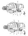
- valves shown comprise a hollow cylinder body (11) designed to be screwed into a tap (not shown) with the interpositioning of a seal (12), the tap being in line with a water delivery conduit, in the direction of the arrow (F) (Fig. 3).
- Valvular parts made up of two overlapping ceramic disks (13, 14), one below the other, are fitted in the cylinder body (11).
- the lower disk (13) is fixed inside the body (11) and is positioned, if necessary through the use of a seal (15), on an axially movable ring (16) which has a bottom seal (17).
- Said disk (13) has at least one hole (13a) for the flow of water coming from the water conduit in the direction of the arrow (F).
- the upper disk (14) rests against and rotates on the lower fixed disk (13) and has at least one hole or slot (14a) positionable in correspondence to and away from the hole (13a) of the fixed disk.
- the fixed disk and the movable disk respectively have two holes (13a) and two slots (14a), whilst in the case of valves with a 180° rotation, the fixed disk and the movable disk respectively have one hole (13a) and one slot (14a).
- the movable disk (14) is splined to an entrainer (18) which is in turn splined to a control rod (19) rotated in the body, operated by a knob (not shown) and has rotation limit stops at 90° and 180°.
- the entrainer (18) has a central bottom tab (18a) which is inserted in a slot (14b) formed on the upper surface of said disk (14).
- the entrainer (18) and/or the cylinder body (11) have lateral openings (20) at the same height of slots (14a) of the movable disk (14) and are designed for the outlet of water from the valve.
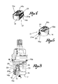
- both types of valves also have an antinoise baffle (21) made of a metal netting.
- Said baffle (21) has a transversal horizontal part (22) designed to rest against the upper surface of the movable disk (14) and to be placed between said disk and the entrainer (18).
- Said part (22) of the net type baffle (21) also has a central slot (22a) which is in correspondence to the upper slot (14b) of the disk (14) and into which the splining tab (18a) of the entrainer (18) is fitted to keep the baffle in place (Fig. 3).
- the net type baffle has one or two wings (23) which extends downwards from the horizontal part (22) and each end with a lower flap (23a) turned upwards towards the outside.
- the antinoise baffle (21) When the antinoise baffle (21) is fitted as in Fig. 3, it is blocked between the upper disk (14) and the entrainer (18) and one or each of its wings (23) orthogonally extend towards the fixed disk near to the slot or slots (14a) of the movable disk (14). The wings extending between these slots and the opening (20) for the outlet of water from the body (11).
- the wings (23) are such a length so as not to reach the lower disk (13) but to remain slightly raised from it; the flap (23a) strengthens the wings so as to prevent them from bending and also improves the validity of the baffle (21).
- this baffle does not reduce the valve flow capacity and allows for the water to flow even when dirt particles are trapped by the net.
- the net dampens water flow turbulence, prevents cavitation of the flow and notably reduces the noise of the valve as has been experimented in test carried out during bad water flow and pressure conditions.
Landscapes
- Engineering & Computer Science (AREA)
- General Engineering & Computer Science (AREA)
- Mechanical Engineering (AREA)
- Sliding Valves (AREA)
- Sealing Material Composition (AREA)
- Domestic Plumbing Installations (AREA)
- Check Valves (AREA)
- Valve Housings (AREA)
- Gasket Seals (AREA)
- Fluid-Damping Devices (AREA)
Applications Claiming Priority (2)
| Application Number | Priority Date | Filing Date | Title |
|---|---|---|---|
| IT697690 | 1990-04-24 | ||
| IT00697690U IT223075Z2 (it) | 1990-04-24 | 1990-04-24 | Schermo antirumore particolarmente per valvole tipo vitone con tenuta a piastrine ceramiche |
Publications (2)
| Publication Number | Publication Date |
|---|---|
| EP0454628A1 true EP0454628A1 (de) | 1991-10-30 |
| EP0454628B1 EP0454628B1 (de) | 1994-12-21 |
Family
ID=11122942
Family Applications (1)
| Application Number | Title | Priority Date | Filing Date |
|---|---|---|---|
| EP91830102A Revoked EP0454628B1 (de) | 1990-04-24 | 1991-03-14 | Geräuschabschirmung für Spindelventile mit Keramikdichtscheiben |
Country Status (10)
| Country | Link |
|---|---|
| US (1) | US5082241A (de) |
| EP (1) | EP0454628B1 (de) |
| JP (1) | JPH08815U (de) |
| AT (1) | ATE116044T1 (de) |
| AU (1) | AU7509691A (de) |
| CA (1) | CA2038231A1 (de) |
| DE (1) | DE69106034T2 (de) |
| DK (1) | DK0454628T3 (de) |
| ES (1) | ES2066410T3 (de) |
| IT (1) | IT223075Z2 (de) |
Families Citing this family (5)
| Publication number | Priority date | Publication date | Assignee | Title |
|---|---|---|---|---|
| AT403514B (de) * | 1995-02-24 | 1998-03-25 | Ideal Standard | Sanitäres wasserventil |
| DE19510289A1 (de) * | 1995-03-22 | 1996-09-26 | Grohe Armaturen Friedrich | Mengenregulierventil |
| AT404293B (de) * | 1995-09-14 | 1998-10-27 | Ideal Standard | Wasserventiloberteil mit in einem gehäuse befindlichen keramischen dichtscheiben |
| US6279605B1 (en) * | 2000-07-05 | 2001-08-28 | Shih-Ming Wang | Water stopping seat of ceramic control valve of faucet |
| US20060086923A1 (en) * | 2004-10-08 | 2006-04-27 | Marotta Controls, Inc. | Rotary valve and control system |
Citations (4)
| Publication number | Priority date | Publication date | Assignee | Title |
|---|---|---|---|---|
| AT4390B (de) * | 1900-06-21 | 1901-06-10 | Harry Bridgman Smith | |
| DE2838195A1 (de) * | 1978-09-01 | 1980-03-13 | Hansa Metallwerke Ag | Einzelventil, insbesondere fuer den sanitaerbereich |
| FR2485147A1 (fr) * | 1980-06-23 | 1981-12-24 | Pont A Mousson | Dispositif de reglage de debit pour robinet |
| EP0103710A1 (de) * | 1982-09-18 | 1984-03-28 | Ideal-Standard Gmbh | Oberteilkartusche für ein sanitäres Einzel-Absperrventil |
Family Cites Families (3)
| Publication number | Priority date | Publication date | Assignee | Title |
|---|---|---|---|---|
| DE2622179C2 (de) * | 1976-05-19 | 1986-04-30 | Ideal-Standard Gmbh, 5300 Bonn | Sanitäres Wasserventil |
| DE3503793C2 (de) * | 1985-02-05 | 1995-09-21 | Grohe Armaturen Friedrich | Mischventil |
| US4657045A (en) * | 1985-02-06 | 1987-04-14 | Kitamuragokin Ind. Co., Ltd. | Noise-preventing structure for water mixing cocks |
-
1990
- 1990-04-24 IT IT00697690U patent/IT223075Z2/it active IP Right Grant
-
1991
- 1991-03-14 AT AT91830102T patent/ATE116044T1/de not_active IP Right Cessation
- 1991-03-14 CA CA002038231A patent/CA2038231A1/en not_active Abandoned
- 1991-03-14 DK DK91830102.9T patent/DK0454628T3/da active
- 1991-03-14 ES ES91830102T patent/ES2066410T3/es not_active Expired - Lifetime
- 1991-03-14 DE DE69106034T patent/DE69106034T2/de not_active Revoked
- 1991-03-14 EP EP91830102A patent/EP0454628B1/de not_active Revoked
- 1991-04-18 AU AU75096/91A patent/AU7509691A/en not_active Abandoned
- 1991-04-23 US US07/689,967 patent/US5082241A/en not_active Expired - Fee Related
- 1991-04-24 JP JP059314U patent/JPH08815U/ja active Pending
Patent Citations (4)
| Publication number | Priority date | Publication date | Assignee | Title |
|---|---|---|---|---|
| AT4390B (de) * | 1900-06-21 | 1901-06-10 | Harry Bridgman Smith | |
| DE2838195A1 (de) * | 1978-09-01 | 1980-03-13 | Hansa Metallwerke Ag | Einzelventil, insbesondere fuer den sanitaerbereich |
| FR2485147A1 (fr) * | 1980-06-23 | 1981-12-24 | Pont A Mousson | Dispositif de reglage de debit pour robinet |
| EP0103710A1 (de) * | 1982-09-18 | 1984-03-28 | Ideal-Standard Gmbh | Oberteilkartusche für ein sanitäres Einzel-Absperrventil |
Also Published As
| Publication number | Publication date |
|---|---|
| IT223075Z2 (it) | 1995-06-09 |
| DE69106034T2 (de) | 1995-05-11 |
| DE69106034D1 (de) | 1995-02-02 |
| ES2066410T3 (es) | 1995-03-01 |
| AU7509691A (en) | 1991-11-07 |
| JPH08815U (ja) | 1996-05-21 |
| IT9006976U1 (it) | 1991-10-25 |
| US5082241A (en) | 1992-01-21 |
| CA2038231A1 (en) | 1991-10-25 |
| ATE116044T1 (de) | 1995-01-15 |
| IT9006976V0 (it) | 1990-04-24 |
| DK0454628T3 (da) | 1995-06-06 |
| EP0454628B1 (de) | 1994-12-21 |
Similar Documents
| Publication | Publication Date | Title |
|---|---|---|
| US3990475A (en) | Low noise valve trim | |
| US11028943B2 (en) | Control butterfly valve | |
| EP2210027B1 (de) | Ventilbetriebsverfahren | |
| US5082241A (en) | Antinoise baffle for screw type valves with ceramic disk seals | |
| CN109937280B (zh) | 排水阀 | |
| US4679595A (en) | Device for controlling the flow in a pipe system | |
| CN111465791B (zh) | 阀和关闭构件 | |
| EP0489296A1 (de) | Kugelhahn mit Durchflusssteueranordnung | |
| US2638929A (en) | Self-throttling valve | |
| KR102656503B1 (ko) | 앵글밸브 | |
| JPS6011333Y2 (ja) | 流量調節弁 | |
| GB2142160A (en) | Valve with anti-cavitation device | |
| US1767919A (en) | Cold-water tube and cleaner for domestic boilers and heaters | |
| KR200480535Y1 (ko) | 복층 시트부 구조를 갖는 글로브 밸브 | |
| RU2029905C1 (ru) | Канализационный клапан | |
| US5850848A (en) | Float valve | |
| CN221610591U (zh) | 一种双通道蝶阀结构 | |
| US1128178A (en) | Convertible spray and jet nozzle. | |
| US965343A (en) | Water-faucet. | |
| DE19525690A1 (de) | Ventil | |
| JPH04337167A (ja) | キャビテーション抑止機能を具えたバタフライ弁 | |
| US3022860A (en) | Air vent device for steam radiators | |
| JPS6223131B2 (de) | ||
| KR102038908B1 (ko) | 캐비테이션 방지 기능을 갖는 밸브 | |
| US937629A (en) | Self-closing water-cock with device to prevent bursting by frost. |
Legal Events
| Date | Code | Title | Description |
|---|---|---|---|
| PUAI | Public reference made under article 153(3) epc to a published international application that has entered the european phase |
Free format text: ORIGINAL CODE: 0009012 |
|
| AK | Designated contracting states |
Kind code of ref document: A1 Designated state(s): AT BE CH DE DK ES FR GB GR IT LI LU NL SE |
|
| 17P | Request for examination filed |
Effective date: 19920411 |
|
| 17Q | First examination report despatched |
Effective date: 19930802 |
|
| GRAA | (expected) grant |
Free format text: ORIGINAL CODE: 0009210 |
|
| ITF | It: translation for a ep patent filed | ||
| AK | Designated contracting states |
Kind code of ref document: B1 Designated state(s): AT BE CH DE DK ES FR GB GR IT LI LU NL SE |
|
| REF | Corresponds to: |
Ref document number: 116044 Country of ref document: AT Date of ref document: 19950115 Kind code of ref document: T |
|
| PGFP | Annual fee paid to national office [announced via postgrant information from national office to epo] |
Ref country code: GB Payment date: 19950113 Year of fee payment: 5 |
|
| PGFP | Annual fee paid to national office [announced via postgrant information from national office to epo] |
Ref country code: DK Payment date: 19950131 Year of fee payment: 5 Ref country code: BE Payment date: 19950131 Year of fee payment: 5 |
|
| PGFP | Annual fee paid to national office [announced via postgrant information from national office to epo] |
Ref country code: LU Payment date: 19950201 Year of fee payment: 5 |
|
| REF | Corresponds to: |
Ref document number: 69106034 Country of ref document: DE Date of ref document: 19950202 |
|
| ET | Fr: translation filed | ||
| PGFP | Annual fee paid to national office [announced via postgrant information from national office to epo] |
Ref country code: ES Payment date: 19950224 Year of fee payment: 5 |
|
| REG | Reference to a national code |
Ref country code: ES Ref legal event code: FG2A Ref document number: 2066410 Country of ref document: ES Kind code of ref document: T3 |
|
| PGFP | Annual fee paid to national office [announced via postgrant information from national office to epo] |
Ref country code: SE Payment date: 19950316 Year of fee payment: 5 |
|
| PGFP | Annual fee paid to national office [announced via postgrant information from national office to epo] |
Ref country code: GR Payment date: 19950322 Year of fee payment: 5 Ref country code: DE Payment date: 19950322 Year of fee payment: 5 |
|
| PGFP | Annual fee paid to national office [announced via postgrant information from national office to epo] |
Ref country code: CH Payment date: 19950328 Year of fee payment: 5 |
|
| PGFP | Annual fee paid to national office [announced via postgrant information from national office to epo] |
Ref country code: FR Payment date: 19950330 Year of fee payment: 5 Ref country code: AT Payment date: 19950330 Year of fee payment: 5 |
|
| PGFP | Annual fee paid to national office [announced via postgrant information from national office to epo] |
Ref country code: NL Payment date: 19950331 Year of fee payment: 5 |
|
| REG | Reference to a national code |
Ref country code: DK Ref legal event code: T3 |
|
| PLBI | Opposition filed |
Free format text: ORIGINAL CODE: 0009260 |
|
| 26 | Opposition filed |
Opponent name: HANSA METALLWERKE AG Effective date: 19950918 |
|
| NLR1 | Nl: opposition has been filed with the epo |
Opponent name: HANSA METALLWERKE AG |
|
| PLBF | Reply of patent proprietor to notice(s) of opposition |
Free format text: ORIGINAL CODE: EPIDOS OBSO |
|
| PG25 | Lapsed in a contracting state [announced via postgrant information from national office to epo] |
Ref country code: LU Free format text: LAPSE BECAUSE OF NON-PAYMENT OF DUE FEES Effective date: 19960314 |
|
| PG25 | Lapsed in a contracting state [announced via postgrant information from national office to epo] |
Ref country code: ES Free format text: LAPSE BECAUSE OF NON-PAYMENT OF DUE FEES Effective date: 19960315 |
|
| PLBF | Reply of patent proprietor to notice(s) of opposition |
Free format text: ORIGINAL CODE: EPIDOS OBSO |
|
| REG | Reference to a national code |
Ref country code: DK Ref legal event code: EBP |
|
| RDAG | Patent revoked |
Free format text: ORIGINAL CODE: 0009271 |
|
| STAA | Information on the status of an ep patent application or granted ep patent |
Free format text: STATUS: PATENT REVOKED |
|
| REG | Reference to a national code |
Ref country code: CH Ref legal event code: PL |
|
| GBPR | Gb: patent revoked under art. 102 of the ep convention designating the uk as contracting state |
Free format text: 960427 |
|
| 27W | Patent revoked |
Effective date: 19960427 |
|
| REG | Reference to a national code |
Ref country code: GR Ref legal event code: MF4A Free format text: 3014714 |
|
| NLR2 | Nl: decision of opposition |