EP0454657B1 - Bandage pneumatique pour véhicules - Google Patents
Bandage pneumatique pour véhicules Download PDFInfo
- Publication number
- EP0454657B1 EP0454657B1 EP91890063A EP91890063A EP0454657B1 EP 0454657 B1 EP0454657 B1 EP 0454657B1 EP 91890063 A EP91890063 A EP 91890063A EP 91890063 A EP91890063 A EP 91890063A EP 0454657 B1 EP0454657 B1 EP 0454657B1
- Authority
- EP
- European Patent Office
- Prior art keywords
- shoulder
- cross
- transverse
- groove
- sectional area
- Prior art date
- Legal status (The legal status is an assumption and is not a legal conclusion. Google has not performed a legal analysis and makes no representation as to the accuracy of the status listed.)
- Expired - Lifetime
Links
- 230000002093 peripheral effect Effects 0.000 abstract 1
- XLYOFNOQVPJJNP-UHFFFAOYSA-N water Substances O XLYOFNOQVPJJNP-UHFFFAOYSA-N 0.000 description 5
- 230000000694 effects Effects 0.000 description 3
- 238000005096 rolling process Methods 0.000 description 2
- 230000001419 dependent effect Effects 0.000 description 1
- 239000000203 mixture Substances 0.000 description 1
Images

Classifications
-
- B—PERFORMING OPERATIONS; TRANSPORTING
- B60—VEHICLES IN GENERAL
- B60C—VEHICLE TYRES; TYRE INFLATION; TYRE CHANGING; CONNECTING VALVES TO INFLATABLE ELASTIC BODIES IN GENERAL; DEVICES OR ARRANGEMENTS RELATED TO TYRES
- B60C11/00—Tyre tread bands; Tread patterns; Anti-skid inserts
- B60C11/01—Shape of the shoulders between tread and sidewall, e.g. rounded, stepped or cantilevered
-
- B—PERFORMING OPERATIONS; TRANSPORTING
- B60—VEHICLES IN GENERAL
- B60C—VEHICLE TYRES; TYRE INFLATION; TYRE CHANGING; CONNECTING VALVES TO INFLATABLE ELASTIC BODIES IN GENERAL; DEVICES OR ARRANGEMENTS RELATED TO TYRES
- B60C11/00—Tyre tread bands; Tread patterns; Anti-skid inserts
- B60C11/03—Tread patterns
- B60C11/0306—Patterns comprising block rows or discontinuous ribs
-
- B—PERFORMING OPERATIONS; TRANSPORTING
- B60—VEHICLES IN GENERAL
- B60C—VEHICLE TYRES; TYRE INFLATION; TYRE CHANGING; CONNECTING VALVES TO INFLATABLE ELASTIC BODIES IN GENERAL; DEVICES OR ARRANGEMENTS RELATED TO TYRES
- B60C11/00—Tyre tread bands; Tread patterns; Anti-skid inserts
- B60C11/03—Tread patterns
- B60C2011/0337—Tread patterns characterised by particular design features of the pattern
- B60C2011/0339—Grooves
- B60C2011/0358—Lateral grooves, i.e. having an angle of 45 to 90 degees to the equatorial plane
Definitions
- the invention relates to a pneumatic vehicle tire with a tread pattern, which is divided by circumferential grooves in the circumferential direction and by transverse grooves in profile elements, a shoulder circumferential groove having a laterally adjacent row of shoulder blocks each with transverse grooves widening toward the tread edge being provided in the tread side areas, in particular the transverse grooves have at least one cross-sectional constriction within the shoulder block rows and the cross-groove cross-section continuously narrows approximately from the shoulder circumferential groove to the point of the smallest cross-sectional area.
- the object is achieved according to the invention in that the smallest cross-sectional area is at least 0.5 Q A and at most 0.95 Q A , Q A being the cross-sectional area of the transverse groove in the region of the mouth to the shoulder circumferential groove.
- the measure according to the invention increases the amount of water that can be removed via the transverse grooves. This effect is due to the fact that the air-water mixture present in the circumferential grooves and the transverse grooves during the rolling of the tire on wet ground is compressible and allows the nozzle effect to be exploited.
- a noticeable improvement in the water drainage capacity is achieved in particular in that the smallest cross-sectional area is at least 0.5 Q A and at most 0.95 Q A , where Q A is the cross-sectional area of the transverse groove in the region of the junction with the shoulder circumferential groove.
- FIG. 1 is a partial development on one half of a tread pattern of a vehicle tire.
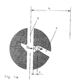
- FIG. 1a shows a detailed view from FIG. 1 on an enlarged scale.
- the tread pattern is composed essentially of circumferential grooves 2, 3, these at least partially crossing transverse grooves 4 and of profile elements, namely of tread bands and / or rows of blocks.
- the tread pattern of the present exemplary embodiment has a central circumferential groove 2 running along the central circumferential line M-M, each of which a tread band 5 adjoining this, which is separated by a shoulder circumferential groove 3 from a row of shoulder blocks 7.
- the width of the tread in the ground contact area of the tire is denoted by B.
- Each shoulder block row 7 has a width b which is at least 20% of the tread width B, in particular between 25 and 30% of the tread width B. This ensures that, together with the selected spacing between adjacent transverse grooves 4, sufficiently stable shoulder blocks 7a are formed.
- the transverse grooves 4 in the area of the shoulder block rows 7 are at least partially designed such that they widen in a trumpet shape towards the edge of the tread.
- the transverse groove course between the individual blocks 7a is specially designed.
- the transverse grooves 4, starting with the shoulder circumferential groove 3 have an area in which there is a continuous reduction in the groove cross section to a point Q min with the smallest cross-sectional area.
- the transverse grooves 4 are widened to the shape of a trumpet towards the tread edge.
- the cross-sectional area Q min is at least 0.5 and at most 0.95 Q A , where Q A is the cross-sectional area of the transverse groove 4 at the edge of the circumferential groove 3.
- the point with the smallest groove cross section Q min is located at a distance 1 from the circumferential groove 3, which is at least 0.1 b, at most 0.6 b.
- the arrangement is made in such a way that there is a transverse groove bend in the transverse groove at the point with the smallest cross section.
- the cross-sectional constriction is preferably also structurally brought about by the fact that the transverse groove side walls converge continuously over region 1, viewed in plan view.
Landscapes
- Engineering & Computer Science (AREA)
- Mechanical Engineering (AREA)
- Tires In General (AREA)
- Pulleys (AREA)
- Turning (AREA)
- Micro-Organisms Or Cultivation Processes Thereof (AREA)
Claims (2)
- Pneumatique pour véhicule comportant un profil de surface de roulement qui est divisé en éléments de sculpture par des gorges périphériques (3) s'étendant dans la direction périphérique et par des gorges transversales (4), ce en quoi il est prévu dans les zones latérales de la surface de roulement respectivement une gorge périphérique d'épaulement (3) avec respectivement une ligne d'épaulement pleine (7) s'y raccordant latéralement, avec des gorges transversales s'élargissant en direction du bord de la surface de roulement, ce en quoi notamment les gorges transversales (4) à l'intérieur des lignes d'épaulement pleines (7) présentent au moins un rétrécissement de section transversale et moyennant quoi la section transversale de la gorge transversale se rétrécit continuellement à partir de la gorge périphérique d'épaulement (3) jusqu'à l'emplacement de la plus petite surface de section transversale (Qmin), caractérisé en ce que la plus petite surface de section transversale (Qmin) est d'au moins 0,5 QA et d'au plus 0,95 QA, ce en quoi la surface de section transversale de la gorge transversale (4) est une zone d'embouchure pour la gorge périphérique d'épaulement (3).
- Pneumatique pour véhicule selon la revendication 1, caractérisé en ce que l'emplacement de la plus petite surface de section transversale (Qmin) se trouve à une distance (ℓ) par rapport à la gorge périphérique d'épaulement (3) qui est d'au moins 0,1 b et d'au plus 0,6 b, moyennant quoi la largeur b de la ligne d'épaulement pleine est mesurée jusqu'au bord de la surface de contact au sol du pneumatique.
Applications Claiming Priority (2)
| Application Number | Priority Date | Filing Date | Title |
|---|---|---|---|
| AT0095290A AT398731B (de) | 1990-04-25 | 1990-04-25 | Fahrzeugluftreifen |
| AT952/90 | 1990-04-25 |
Publications (3)
| Publication Number | Publication Date |
|---|---|
| EP0454657A2 EP0454657A2 (fr) | 1991-10-30 |
| EP0454657A3 EP0454657A3 (fr) | 1991-12-11 |
| EP0454657B1 true EP0454657B1 (fr) | 1993-09-29 |
Family
ID=3503601
Family Applications (1)
| Application Number | Title | Priority Date | Filing Date |
|---|---|---|---|
| EP91890063A Expired - Lifetime EP0454657B1 (fr) | 1990-04-25 | 1991-04-02 | Bandage pneumatique pour véhicules |
Country Status (3)
| Country | Link |
|---|---|
| EP (1) | EP0454657B1 (fr) |
| AT (2) | AT398731B (fr) |
| DE (1) | DE59100417D1 (fr) |
Families Citing this family (5)
| Publication number | Priority date | Publication date | Assignee | Title |
|---|---|---|---|---|
| JP2702873B2 (ja) * | 1992-09-16 | 1998-01-26 | 住友ゴム工業株式会社 | ラジアルタイヤ |
| DE102010060616A1 (de) * | 2010-11-17 | 2012-05-24 | Continental Reifen Deutschland Gmbh | Laufstreifenprofil eines Fahrzeugluftreifens |
| JP5557821B2 (ja) | 2011-10-13 | 2014-07-23 | 株式会社ブリヂストン | 空気入りタイヤ |
| JP5557875B2 (ja) * | 2012-05-18 | 2014-07-23 | 株式会社ブリヂストン | 空気入りタイヤ |
| CN114987659A (zh) * | 2022-07-13 | 2022-09-02 | 东莞市卓蓝自动化设备有限公司 | 一种新能源电池转运agv小车 |
Family Cites Families (3)
| Publication number | Priority date | Publication date | Assignee | Title |
|---|---|---|---|---|
| US4356985A (en) * | 1981-02-26 | 1982-11-02 | The Goodyear Tire & Rubber Company | Aircraft tire |
| US4456046A (en) * | 1981-05-11 | 1984-06-26 | Miller Timothy I | High-speed tires |
| JPS6452507A (en) * | 1987-05-08 | 1989-02-28 | Bridgestone Corp | Pneumatic tire pair |
-
1990
- 1990-04-25 AT AT0095290A patent/AT398731B/de not_active IP Right Cessation
-
1991
- 1991-04-02 EP EP91890063A patent/EP0454657B1/fr not_active Expired - Lifetime
- 1991-04-02 AT AT91890063T patent/ATE95118T1/de not_active IP Right Cessation
- 1991-04-02 DE DE91890063T patent/DE59100417D1/de not_active Expired - Fee Related
Non-Patent Citations (1)
| Title |
|---|
| & JP-A-61 036 002 (BRIDGESTONE CORP. ) 20. Februar 1986 * |
Also Published As
| Publication number | Publication date |
|---|---|
| ATA95290A (de) | 1994-06-15 |
| EP0454657A3 (fr) | 1991-12-11 |
| DE59100417D1 (de) | 1993-11-04 |
| AT398731B (de) | 1995-01-25 |
| ATE95118T1 (de) | 1993-10-15 |
| EP0454657A2 (fr) | 1991-10-30 |
Similar Documents
| Publication | Publication Date | Title |
|---|---|---|
| DE3017306C2 (fr) | ||
| DE69400484T2 (de) | Reifenlauffläche | |
| AT400425B (de) | Fahrzeugreifen | |
| DE3707953C2 (fr) | ||
| EP1029712B1 (fr) | Bandage pneumatique pour véhicule | |
| EP0296605B1 (fr) | Bandage pneumatique | |
| DE69933260T2 (de) | Verfahren zum Gestalten eines Laufflächenprofils für Fahrzeugreifen | |
| DE69513926T2 (de) | Luftreifen | |
| DE3737264A1 (de) | Luftradialreifen | |
| DE4237559A1 (fr) | ||
| DE2035714A1 (de) | Luftreifen | |
| EP0729854B1 (fr) | Bandage pneumatique pour véhicule | |
| DE2319526A1 (de) | Luftreifen | |
| DE3013958A1 (de) | Laufflaeche fuer die reifen eines landfahrzeuges | |
| DE10032372B4 (de) | Fahrzeugreifen | |
| EP0788898B1 (fr) | Bandage pneumatique pour véhicule | |
| DE3624408A1 (de) | Fahrzeugluftreifen | |
| DE69202606T2 (de) | Luftreifen. | |
| DE19957915A1 (de) | Fahrzeugluftreifen | |
| DE2816626A1 (de) | Hochleistungs-luftreifen in radial- bauweise | |
| EP2217455B1 (fr) | Pneumatique de véhicule | |
| AT394525B (de) | Fahrzeugluftreifen | |
| DE2536470C2 (de) | Luftbereifung für Straßenfahrzeuge | |
| AT398731B (de) | Fahrzeugluftreifen | |
| DE950828C (de) | Laufflaeche fuer Luftreifen |
Legal Events
| Date | Code | Title | Description |
|---|---|---|---|
| PUAI | Public reference made under article 153(3) epc to a published international application that has entered the european phase |
Free format text: ORIGINAL CODE: 0009012 |
|
| PUAL | Search report despatched |
Free format text: ORIGINAL CODE: 0009013 |
|
| AK | Designated contracting states |
Kind code of ref document: A2 Designated state(s): AT DE FR GB IT |
|
| AK | Designated contracting states |
Kind code of ref document: A3 Designated state(s): AT DE FR GB IT |
|
| 17P | Request for examination filed |
Effective date: 19911113 |
|
| 17Q | First examination report despatched |
Effective date: 19920714 |
|
| GRAA | (expected) grant |
Free format text: ORIGINAL CODE: 0009210 |
|
| AK | Designated contracting states |
Kind code of ref document: B1 Designated state(s): AT DE FR GB IT |
|
| REF | Corresponds to: |
Ref document number: 95118 Country of ref document: AT Date of ref document: 19931015 Kind code of ref document: T |
|
| REF | Corresponds to: |
Ref document number: 59100417 Country of ref document: DE Date of ref document: 19931104 |
|
| ITF | It: translation for a ep patent filed | ||
| ET | Fr: translation filed | ||
| GBT | Gb: translation of ep patent filed (gb section 77(6)(a)/1977) |
Effective date: 19940106 |
|
| PLBE | No opposition filed within time limit |
Free format text: ORIGINAL CODE: 0009261 |
|
| STAA | Information on the status of an ep patent application or granted ep patent |
Free format text: STATUS: NO OPPOSITION FILED WITHIN TIME LIMIT |
|
| 26N | No opposition filed | ||
| PGFP | Annual fee paid to national office [announced via postgrant information from national office to epo] |
Ref country code: GB Payment date: 19980312 Year of fee payment: 8 |
|
| PGFP | Annual fee paid to national office [announced via postgrant information from national office to epo] |
Ref country code: FR Payment date: 19980313 Year of fee payment: 8 |
|
| PGFP | Annual fee paid to national office [announced via postgrant information from national office to epo] |
Ref country code: DE Payment date: 19980318 Year of fee payment: 8 |
|
| PGFP | Annual fee paid to national office [announced via postgrant information from national office to epo] |
Ref country code: AT Payment date: 19980324 Year of fee payment: 8 |
|
| PG25 | Lapsed in a contracting state [announced via postgrant information from national office to epo] |
Ref country code: GB Free format text: LAPSE BECAUSE OF NON-PAYMENT OF DUE FEES Effective date: 19990402 Ref country code: AT Free format text: LAPSE BECAUSE OF NON-PAYMENT OF DUE FEES Effective date: 19990402 |
|
| GBPC | Gb: european patent ceased through non-payment of renewal fee |
Effective date: 19990402 |
|
| PG25 | Lapsed in a contracting state [announced via postgrant information from national office to epo] |
Ref country code: FR Free format text: LAPSE BECAUSE OF NON-PAYMENT OF DUE FEES Effective date: 19991231 |
|
| REG | Reference to a national code |
Ref country code: FR Ref legal event code: ST |
|
| PG25 | Lapsed in a contracting state [announced via postgrant information from national office to epo] |
Ref country code: DE Free format text: LAPSE BECAUSE OF NON-PAYMENT OF DUE FEES Effective date: 20000201 |
|
| PG25 | Lapsed in a contracting state [announced via postgrant information from national office to epo] |
Ref country code: IT Free format text: LAPSE BECAUSE OF NON-PAYMENT OF DUE FEES;WARNING: LAPSES OF ITALIAN PATENTS WITH EFFECTIVE DATE BEFORE 2007 MAY HAVE OCCURRED AT ANY TIME BEFORE 2007. THE CORRECT EFFECTIVE DATE MAY BE DIFFERENT FROM THE ONE RECORDED. Effective date: 20050402 |