EP0454709B1 - Vehicule, notamment chassis de dispositif de controle a pont - Google Patents
Vehicule, notamment chassis de dispositif de controle a pont Download PDFInfo
- Publication number
- EP0454709B1 EP0454709B1 EP90901740A EP90901740A EP0454709B1 EP 0454709 B1 EP0454709 B1 EP 0454709B1 EP 90901740 A EP90901740 A EP 90901740A EP 90901740 A EP90901740 A EP 90901740A EP 0454709 B1 EP0454709 B1 EP 0454709B1
- Authority
- EP
- European Patent Office
- Prior art keywords
- frame
- vehicle
- axle
- wheels
- axle unit
- Prior art date
- Legal status (The legal status is an assumption and is not a legal conclusion. Google has not performed a legal analysis and makes no representation as to the accuracy of the status listed.)
- Expired - Lifetime
Links
- 238000007689 inspection Methods 0.000 title claims abstract description 5
- 239000000725 suspension Substances 0.000 claims abstract description 9
- 241000272165 Charadriidae Species 0.000 description 1
- 235000004443 Ricinus communis Nutrition 0.000 description 1
- 240000000528 Ricinus communis Species 0.000 description 1
- 238000010276 construction Methods 0.000 description 1
- 230000005484 gravity Effects 0.000 description 1
- 230000007246 mechanism Effects 0.000 description 1
- 239000004033 plastic Substances 0.000 description 1
Images
Classifications
-
- E—FIXED CONSTRUCTIONS
- E01—CONSTRUCTION OF ROADS, RAILWAYS, OR BRIDGES
- E01D—CONSTRUCTION OF BRIDGES, ELEVATED ROADWAYS OR VIADUCTS; ASSEMBLY OF BRIDGES
- E01D19/00—Structural or constructional details of bridges
- E01D19/10—Railings; Protectors against smoke or gases, e.g. of locomotives; Maintenance travellers; Fastening of pipes or cables to bridges
- E01D19/106—Movable inspection or maintenance platforms, e.g. travelling scaffolding or vehicles specially designed to provide access to the undersides of bridges
-
- B—PERFORMING OPERATIONS; TRANSPORTING
- B66—HOISTING; LIFTING; HAULING
- B66F—HOISTING, LIFTING, HAULING OR PUSHING, NOT OTHERWISE PROVIDED FOR, e.g. DEVICES WHICH APPLY A LIFTING OR PUSHING FORCE DIRECTLY TO THE SURFACE OF A LOAD
- B66F11/00—Lifting devices specially adapted for particular uses not otherwise provided for
- B66F11/04—Lifting devices specially adapted for particular uses not otherwise provided for for movable platforms or cabins, e.g. on vehicles, permitting workmen to place themselves in any desired position for carrying out required operations
- B66F11/044—Working platforms suspended from booms
Definitions
- the invention relates to a vehicle, in particular the chassis of a bridge underside device, with a frame, with an axle assembly with at least one Road vehicle wheels equipped axle and with a pressure-operated device for lifting and lowering the frame. It can be assumed that a vehicle is moving on public roads at about the speed of a truck.
- EP-A-O 134 311 Another vehicle of the type described in the introduction is known from EP-A-O 134 311.
- the device for lifting and lowering the frame consists of supports with wheels that can be moved hydraulically in the vertical and lateral directions. If these are extended downwards until the road vehicle wheels are relieved, the latter are raised on the swiveling yokes so far that they go laterally over the guardrails.
- vehicles in particular trucks, with pressure medium-operated, in particular air-sprung, rear axles are generally known.
- These axles are pivoted up and down on the frame by means of two trailing arms and are supported on the frame by two air bellows or cylinder arrangements.
- the frame By reducing the pressure in the bellows or cylinders, the frame, possibly with the load, can be lowered so far that it rests on unsprung stops of the axles.
- the frame can be raised again by increasing the pressure and the suspension behavior required for road travel can be restored.
- This change in height is known to be used to carry out a rapid charge change, e.g. B. to pick up or put down a container standing on stilts.
- the invention has for its object to propose a vehicle that takes over both the function of a road transport chassis and the function of an operating chassis, requires relatively low investment costs and can be quickly and easily changed from one to the other mode.
- the main difference of this vehicle compared to known convertible chassis for bridge underside devices or similar devices is that the unsprung additional wheels are not adjustable in height, at least under load on the frame, but the frame is lowered until these additional wheels come into contact with the ground.
- the frame is also not lowered by means of devices which are assigned to the additional wheels, but rather with the aid of the pressure-sprung axle assembly.
- Commercially available standard axles can be used, which are relatively inexpensive and special lifting devices on the additional wheels are unnecessary.
- the maximum stroke of the pressure-operated height adjustment devices of standard truck axles is only about 12 cm. But that is enough, because the same rubber-tired wheels are expediently used as additional wheels as with the pressure-sprung axle units. So if the auxiliary wheels occasionally touch the ground occasionally when driving on the road as a result of bumps or when the spring-loaded wheels are extremely compressed, that does no harm. The additional wheels then simply run along.
- the pressure-sprung axle assembly can consist of one or more axles.
- the number of additional wheels is determined by the required stability. Under certain circumstances, a single additional wheel may be sufficient. It is better to have two additional wheels, one of which is arranged in front of and one behind the axle assembly, preferably on the side facing the edge of the bridge during operation of the bridge inspection device. It is even more advantageous to provide at least one additional axle with two additional wheels.
- This additional axle can also be attached in front of or behind the pressure-sprung axle assembly or one additional axle in front and one behind.
- the auxiliary wheels preferably run in the same track as the wheels of the sprung axle assembly.
- At least one additional wheel or an additional axle be designed to be steerable.
- a simple steering device is sufficient since only small steering deflections are required.
- a steering device is expedient, which normally assumes a central position and makes predetermined fixed deflections when the signal "left" or signal "right”.
- the auxiliary wheels are also suitable for the arrangement of a slow drive.
- the additional wheels or additional axles are not attached to the frame in a height-adjustable manner, their ground clearance when driving on the road is determined by the lifting height of the pressure-operated lowering device. If exceptionally a greater ground clearance is desired, however, an adjustment device can be attached to the relevant additional axis, with the aid of which this axis can be moved unloaded between two different high positions and locked in these positions on the frame. In particular here is simple to think of manually operated adjustment devices. Attaching them can also be worthwhile insofar as the choice of a pressure-sprung axle unit with a relatively small stroke is more cost-effective.
- the mentioned fixed stops of the axles of the pressure-sprung axle assembly, on which the frame lies when it is lowered, are located relatively far inside, ie. H. at a small distance from the median longitudinal plane of the vehicle.
- the support base of the frame on these axles when tilting in the transverse direction is thus much smaller than the track width.
- An important further development of the invention is that an axially parallel support roller is arranged on the frame via at least one wheel of the axle assembly, to which the tire of the wheel in question lies with its tread in the lower position of the frame.
- a plurality of support rollers can also be provided for one wheel.
- the main advantage of these support rollers is that the tilting edge of the frame is moved outwards with respect to the axes, and the stability of the frame is thereby considerably increased.
- Another advantage of such support rollers is that they can be equipped with a hydraulic slow drive, for example.
- the backup rollers then act as driving friction wheels on the rubber tires. The backup rollers do not touch the tires in road transport operations.
- the additional wheels have tires with a harder suspension behavior than the tires of the wheels of the axle assembly.
- the tires can be foamed with plastic, for example. If necessary, the auxiliary wheels or some of them can be pulled out in the axial direction, so that this allows the footprint to be increased.
- the height of the additional wheels and the stops on the frame is expediently chosen so that when the frame is lowered into the lower position, the total axle load is evenly distributed over the existing axles.
- the proposed vehicle can be designed as a self-driving truck, as a trailer or as a semi-trailer.
- the steerable axle can also be used for steering in work mode.
- a bridge underside device such a vehicle can also be used for mobile lifts, mobile high-work platforms or for working machines, e.g. B. road construction machines, use.
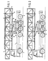
- the truck according to FIGS. 1 and 2 has a frame 1 designed as a flat platform and a total of five axles which are provided with rubber tires of the same size as are usually used for road transport vehicles of this type.
- the front axle 2 is steerable and sprung as usual.
- the two middle rear axles are the drive axles. They form an axle assembly 3 with compressed air suspension and a device for height adjustment.
- the two axles mentioned are pivoted on the vehicle frame with the aid of trailing arms 4.
- the air-filled bellows are indicated by 5.
- an axially parallel support roller 6 is arranged at a distance of approximately 12 cm.
- axle 7 and 8 In front of and behind the axle assembly 3 there is an additional axle 7 and 8, respectively, which are fixed, ie not resilient, to the frame 1.
- the additional wheels run in the track of the wheels of the axle assembly 3.
- the wheels of the additional axles 7 and 8 are so high that they are at a distance of about 12 cm from the road surface.
- the one attached to frame 1 Bridge underside device consists essentially of a lifting tower 9 and a work platform 10 which is tilted by 90 ° so that its bottom is vertical.
- the lifting tower has a lower tower section 12 which can be rotated about the tower axis by means of a turntable 11.
- the work bridge 10 is pivoted thereon about a transverse axis 13.
- the lifting tower 9 is mounted on a guide frame 14 so as to be displaceable in the longitudinal direction.
- This guide frame is articulated on a snap frame 17 by means of parallel levers 15 and 16. This in turn is movably mounted about a horizontal transverse axis 18 on a turntable 19 which rotates on the frame 1 about a vertical axis 20.
- the vehicle With the folded-down bridge underside device and the three sprung pneumatic tires according to FIG. 1, the vehicle is suitable for road transport operation.
- the support rollers 6 are exposed and the wheels of the additional axles 7 and 8 have no ground contact.
- the vehicle Before erecting the underside of the bridge, the vehicle is prepared for the working position according to FIG. 2 by lowering the frame 1. By reducing the air pressure in the bellows 5, these are compressed under the weight of the loaded frame and shorten. The frame sinks down until the additional wheels come into contact with the ground and are loaded.
- the bearing blocks 21 of the trailing arms have also been lowered and the support rollers 6 press on the tires of the axle assembly 3.
- the total axle load of the rear vehicle section is thus distributed from two to four axles.
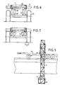
- FIG. 6 and 7 in particular show the support rollers 6 more clearly. These have a continuous shaft 22 and are constructed in such a way that they can absorb the considerable radial forces of the wheels of the axle assembly 3, which are designated 23 here.
- the upper stops 24 attached to the frame 1 come into contact with the lower stops 25 attached to the axle.
- the outer lateral boundary edges of the stops 24 running in the longitudinal direction of the vehicle are the decisive tilting edges of the vehicle body.
- these tilting edges are moved laterally outwards by a distance a.
- the support rollers thus make a significant contribution to the stability of such a device in work.
- the frictional contact between the support rollers and the wheels 23 is used for slowly moving the vehicle on the bridge.
- the hydraulic motors (not shown) which engage the support rollers can also be remotely controlled from the work platform.
- the front axle 2, which can be equipped with a remote control add-on, is used for steering.
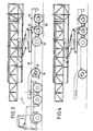
- FIGS. 3 to 5 show, as a second exemplary embodiment, a semi-trailer on which an identical bridge underside device is constructed.
- the frame 26, which is also designed as a platform, is in the upper position for road transport.
- the towing vehicle 27 is coupled.
- the trailer has four axles.
- the two rear axles form an axle assembly 28 with compressed air suspension.
- a small hydraulic lifting cylinder 32 or a manually operated winch between an upper and lower position, so that this additional axis 30 can be lowered and raised by about 10 cm.
- the additional axis 29 has a ground clearance of 12 cm.
- the axle assembly 28 springs.
- a backup roller 33 above the last wheel and a pair of backup rollers 34 above the penultimate wheel are disengaged.
- the uncoupling from the towing vehicle 27 takes place in such a way that the additional axis 30 is first brought into its lower position and locked, so that both additional axes have the same ground clearance of 12 cm.
- the compressed air operated lowering devices are actuated both on the towing vehicle and on the axle assembly 28. All four axles of the semi-trailer thus assume the total axle load, as shown in FIG. 4.
- the towing vehicle 27 can move away.
- the backup rolls which also have a slow hydraulic drive in this example, are engaged. With the simple steering device of the additional axle 30, the vehicle can follow the predetermined lane on the bridge.
- the turntable 19 is rotated about its vertical axis 20 and at the same time the folding frame 17 is pivoted up about its axis 18 by means of a lifting cylinder, which is indicated by dash-dotted lines.
- the lower part of the tower 12 thus moves over the parapet of the bridge and pivots further downward.
- the parallel arms 15, 16, also by means of a stroke cylinder indicated by dash-dotted lines, from the snap frame 17 are pivoted away.
- the semi-trailer could e.g. B. have a sprung axle assembly with three axles.
- An additional axle could also be arranged behind the axle assembly, the front additional axle 30, which can be lifted off without load, depending on the longitudinal position of the center of gravity of the vehicle.
- one or more additional axles should be steerable. More or fewer axles could also be provided in the truck. It would also be advantageous to be able to steer the rear additional axle behind the sprung axle assembly.
Landscapes
- Engineering & Computer Science (AREA)
- Structural Engineering (AREA)
- Architecture (AREA)
- Civil Engineering (AREA)
- Life Sciences & Earth Sciences (AREA)
- Geology (AREA)
- Mechanical Engineering (AREA)
- Vehicle Body Suspensions (AREA)
- Bridges Or Land Bridges (AREA)
- Forklifts And Lifting Vehicles (AREA)
Abstract
Claims (10)
- Véhicule, en particulier châssis d'un dispositif pour l'inspection du dessous d'un pont, comportant un châssis (1,26), un groupe d'essieux (3,28) comportant au moins un essieu équipé de roues de véhicule routier (23), et un dispositif (4,5) pouvant être actionné par du fluide sous pression pour soulever et abaisser le châssis,
caractérisé en ce que le jeu d'essieux (3) est suspendu par du fluide sous pression, en ce que le dispositif (4,5) est relié à l'installation de suspension, en ce que, à l'aide du dispositif (4,5), le châssis (1,26) peut être abaissé d'une position supérieure, dans laquelle la suspension est efficace, dans une position inférieure dans laquelle le châssis repose, de façon non suspendue, sur des butées de support (24,25) des essieux de ce groupe d'essieux, et en ce que, devant et/ou derrière le groupe d'essieux (3,28), au moins une roue supplémentaire non suspendue est agencée sur le châssis (1,26), laquelle roue supplémentaire, dans la position supérieure du châssis, est soulevée de la voie routière, est abaissée en même temps que le châssis (1,26) et, dans la position inférieure du chassis, repose sur la voie routière et reçoit une partie de la charge totale des essieux. - Véhicule selon la revendication 1,
caractérisé en ce qu'au moins un essieu supplémentaire (7,8,29,30) comportant deux roues supplémentaires est prévu. - Véhicule selon la revendication 1,
caractérisé en ce qu'au moins une roue supplémentaire peut être dirigée. - Véhicule selon la revendication 2,
caractérisé en ce qu'un essieu supplémentaire (30) présente un dispositif de réglage (31,32) à l'aide duquel il peut être déplacé, de façon non chargée, entre deux positions de hauteurs différentes et peut être bloqué dans ces positions sur le châssis (26). - Véhicule selon la revendication 1,
caractérisé par une réalisation en tant que semi-remorque (figure 3). - Véhicule selon la revendication 1,
caractérisé en ce qu'au moins une des roues présente un entraînement à petite vitesse. - Véhicule selon la revendication 1,
caractérisé en ce que, sur le châssis (1,26), au-dessus d'au moins une roue du groupe d'essieux (3,28), est agencé un rouleau d'appui parallèle à l'axe (6,33,34), sur lequel s'appuie, dans la position inférieure du châssis, le bandage de la roue par sa surface de roulement. - Véhicule selon la revendication 7,
caractérisé en ce que plusieurs rouleaux d'appui (34) sont prévus pour une roue. - Véhicule selon la revendication 7,
caractérisé en ce que le rouleau d'appui peut être entraîné à petite vitesse. - Véhicule selon la revendication 1,
caractérisé en ce que les roues supplémentaires présentent des bandages ayant un comportement plus dur à la suspension que les bandages des roues du groupe d'essieux.
Priority Applications (1)
| Application Number | Priority Date | Filing Date | Title |
|---|---|---|---|
| AT90901740T ATE95864T1 (de) | 1989-01-23 | 1990-01-23 | Fahrzeug, insbesondere fahrgestell einer brueckenuntersichtvorrichtung. |
Applications Claiming Priority (2)
| Application Number | Priority Date | Filing Date | Title |
|---|---|---|---|
| DE8900673U DE8900673U1 (de) | 1989-01-23 | 1989-01-23 | Fahrzeug mit einem druckmittelgefederten Achsaggregat |
| DE8900673U | 1989-01-23 |
Publications (2)
| Publication Number | Publication Date |
|---|---|
| EP0454709A1 EP0454709A1 (fr) | 1991-11-06 |
| EP0454709B1 true EP0454709B1 (fr) | 1993-10-13 |
Family
ID=6835264
Family Applications (1)
| Application Number | Title | Priority Date | Filing Date |
|---|---|---|---|
| EP90901740A Expired - Lifetime EP0454709B1 (fr) | 1989-01-23 | 1990-01-23 | Vehicule, notamment chassis de dispositif de controle a pont |
Country Status (8)
| Country | Link |
|---|---|
| US (1) | US5167295A (fr) |
| EP (1) | EP0454709B1 (fr) |
| JP (1) | JP2901753B2 (fr) |
| AU (1) | AU632784B2 (fr) |
| CA (1) | CA2045635A1 (fr) |
| DE (2) | DE8900673U1 (fr) |
| ES (1) | ES2047914T3 (fr) |
| WO (1) | WO1990008228A1 (fr) |
Families Citing this family (16)
| Publication number | Priority date | Publication date | Assignee | Title |
|---|---|---|---|---|
| DE8910749U1 (de) * | 1989-09-08 | 1991-02-07 | Moog, Alfons, 7774 Deggenhausertal | Brückenuntersichtvorrichtung |
| EP0662068A4 (fr) * | 1992-09-23 | 1996-01-03 | Pallet Boss Pty Ltd | Vehicules destines a transporter des charges. |
| US6598702B1 (en) * | 2000-07-13 | 2003-07-29 | Mcgillewie, Jr. Garth E. | Under bridge access apparatus with cross-linking member connecting tower with vehicular chassis |
| US6698371B1 (en) | 2002-10-28 | 2004-03-02 | Harold A. Stoltzfus | Boat with personnel elevator apparatus |
| US7134829B2 (en) | 2004-03-09 | 2006-11-14 | Absolute Electronic Solutions, Inc. | Cargo trailer |
| US7950675B1 (en) | 2005-05-13 | 2011-05-31 | Absolute Electronic Solutions, Inc. | Cargo carrier |
| US7406919B2 (en) * | 2005-11-02 | 2008-08-05 | Coots William R | Method and apparatus for operating a vehicle on rails of a railroad track with an auxiliary drive assembly |
| WO2009158329A2 (fr) | 2008-06-27 | 2009-12-30 | Absolute Electronic Solutions, Inc. | Véhicule tracteur de semi-remorque à plateau réglable |
| GB2488983C (en) * | 2011-03-08 | 2014-12-03 | Suspended structure, scaffolding or formwork system | |
| GB2506944B (en) | 2012-10-15 | 2017-02-22 | Niftylift Ltd | Base unit for a vehicle |
| US9446662B2 (en) | 2013-02-22 | 2016-09-20 | B & B Metals, Inc. | Auxiliary drive system |
| CN103306201B (zh) * | 2013-07-11 | 2015-02-04 | 鞍山森远路桥股份有限公司 | 道路桥梁快速维修工程车 |
| CN104947586A (zh) * | 2015-04-28 | 2015-09-30 | 湖南桥康智能科技有限公司 | 桥梁检测作业车 |
| CN104950913A (zh) * | 2015-05-19 | 2015-09-30 | 湖南桥康智能科技有限公司 | 桥梁检测机器人臂架的一键展开控制系统 |
| CN105862587B (zh) * | 2016-05-27 | 2017-05-31 | 北京恒力铁科技术开发有限公司 | 一种桥梁检查车及检测方法 |
| IT202200023379A1 (it) * | 2022-11-14 | 2024-05-14 | Weico Srl | Veicolo e/o rimorchio con piattaforma per l’ispezione di ponti |
Family Cites Families (17)
| Publication number | Priority date | Publication date | Assignee | Title |
|---|---|---|---|---|
| US676409A (en) * | 1901-01-09 | 1901-06-18 | Paul E Berger | Vehicle. |
| US1005291A (en) * | 1911-04-29 | 1911-10-10 | Edwin G Owen | Friction driving mechanism for motor-vehicles. |
| FR865385A (fr) * | 1940-01-20 | 1941-05-21 | Const Mecaniques Chenard & Wal | Perfectionnements aux véhicules pour tous terrains |
| US3262517A (en) * | 1964-11-18 | 1966-07-26 | Jerry P Malec | Bridge crane |
| US3502165A (en) * | 1967-01-16 | 1970-03-24 | Kosuke Matsukata | Gas-electric driven vehicle with retractable wheels |
| FR2256066B1 (fr) * | 1974-10-09 | 1977-03-18 | Ppm Sa | |
| DE2711214A1 (de) * | 1977-03-15 | 1979-01-25 | Josef Dipl Ing Koza | Hilfsantrieb fuer nicht angetriebene raeder von kraftfahrzeugen |
| US4318451A (en) * | 1980-05-27 | 1982-03-09 | The Warner & Swasey Company | Dual function remote steering control |
| NL8103962A (nl) * | 1980-12-11 | 1982-07-01 | Moessbauer & Soehne | Asaggregaat met ten minste twee assen, in het bijzonder voor opleggers met meer dan een as voor trailervoertuigen. |
| DE3305384A1 (de) * | 1982-09-14 | 1984-03-15 | Alfons 7774 Deggenhausertal Moog | Einrichtung zur inspektion der unterseite von bruecken |
| DE3309729A1 (de) * | 1983-03-18 | 1984-09-27 | Bergische Achsenfabrik Fr. Kotz & Söhne, 5276 Wiehl | Achsanhebevorrichtung |
| DE3332227C2 (de) * | 1983-09-07 | 1985-07-25 | Peter 5800 Hagen Cramer | Brückenuntersichtgerät |
| DE8337221U1 (de) * | 1983-12-24 | 1984-04-05 | Moog, Alfons, 7774 Deggenhausertal | Brückenuntersichtgerät |
| EP0205265B1 (fr) * | 1985-05-30 | 1989-08-16 | Toyota Jidosha Kabushiki Kaisha | Véhicule pour travail en hauteur |
| FR2590537A1 (fr) * | 1985-11-22 | 1987-05-29 | Maupu Sarl Bennes | Benne de gros tonnages assurant une grande repartition de la charge au sol et presentant une grande maniabilite |
| US4846581A (en) * | 1987-04-07 | 1989-07-11 | Osterlund Inc. | Rear discharge-two way concrete mixer |
| FR2623755B1 (fr) * | 1987-11-30 | 1990-05-04 | Prefabrication Elect Ste Indle | Dispositif permettant d'abaisser l'arriere d'un vehicule routier pour l'amener au niveau du sol |
-
1989
- 1989-01-23 DE DE8900673U patent/DE8900673U1/de not_active Expired - Lifetime
-
1990
- 1990-01-23 EP EP90901740A patent/EP0454709B1/fr not_active Expired - Lifetime
- 1990-01-23 WO PCT/DE1990/000038 patent/WO1990008228A1/fr not_active Ceased
- 1990-01-23 CA CA002045635A patent/CA2045635A1/fr not_active Abandoned
- 1990-01-23 AU AU48429/90A patent/AU632784B2/en not_active Ceased
- 1990-01-23 ES ES90901740T patent/ES2047914T3/es not_active Expired - Fee Related
- 1990-01-23 DE DE90901740T patent/DE59003091D1/de not_active Expired - Fee Related
- 1990-01-23 US US07/721,637 patent/US5167295A/en not_active Expired - Lifetime
- 1990-01-23 JP JP2501942A patent/JP2901753B2/ja not_active Expired - Lifetime
Also Published As
| Publication number | Publication date |
|---|---|
| WO1990008228A1 (fr) | 1990-07-26 |
| JP2901753B2 (ja) | 1999-06-07 |
| JPH04502792A (ja) | 1992-05-21 |
| EP0454709A1 (fr) | 1991-11-06 |
| DE59003091D1 (de) | 1993-11-18 |
| CA2045635A1 (fr) | 1990-07-24 |
| AU632784B2 (en) | 1993-01-14 |
| US5167295A (en) | 1992-12-01 |
| DE8900673U1 (de) | 1990-06-07 |
| ES2047914T3 (es) | 1994-03-01 |
| AU4842990A (en) | 1990-08-13 |
Similar Documents
| Publication | Publication Date | Title |
|---|---|---|
| EP0454709B1 (fr) | Vehicule, notamment chassis de dispositif de controle a pont | |
| DE3410952A1 (de) | Brueckenuntersichtvorrichtung | |
| DE3305384A1 (de) | Einrichtung zur inspektion der unterseite von bruecken | |
| DE2837398A1 (de) | Fahrzeugkran | |
| DE3405259C2 (de) | Straßentieflader, insbesondere Tiefladeranhänger für Sattelzugmaschinen | |
| DE9406572U1 (de) | Fahrwerk, insbesondere für mobile Arbeitsgeräte und Fahrzeuge | |
| EP0919508B1 (fr) | Grue avec un dispositif de retenue | |
| DE19948143C2 (de) | Schienendrehgestell mit integriertem Neigungsausgleich für Zweiwegefahrzeuge | |
| DE19512246A1 (de) | Selbstfahrendes und selbstauf- und abladbares Verladesystem für Container oder Wechselbrücken | |
| DE19903132B4 (de) | Nick- und Ausdrehvorrichtung für ein Schienenfahrzeug | |
| DE4024825C1 (en) | Support legs for semi-trailer - has inner tube sections with supports for feet which pivot | |
| DE19708750A1 (de) | Fahrwerk für einen Kran, vorzugsweise Portalkran | |
| EP0286576B1 (fr) | Véhicule de transport | |
| EP0732300B1 (fr) | Engin mobile de travail | |
| DE2653278A1 (de) | Tieflader, insbesondere auflieger fuer den strassentransport von sperrigen lasten, z.b. von glasscheiben in aufrechter stellung | |
| DE3147942A1 (de) | Verfahren zum aufrichten eines oben drehenden turmkranes und turmkran zur durchfuehrung eines derartigen verfahrens | |
| DE4126979C2 (de) | Vorrichtung und Verfahren zur Nivellierung von auf Transportfahrzeugen montierten Teleskopmasten | |
| DE3807515C1 (en) | Supporting structure for lifting vehicles under the wheels | |
| EP0399233B1 (fr) | Echafaudage élévateur | |
| DE2936160A1 (de) | Anlage zum verladen schwerer lasten auf lastfahrzeuge o.dgl. mittels belademaschine | |
| EP0945399B1 (fr) | Plate-forme de travail mobile à trois véhicules | |
| DE2314503C2 (de) | Turmkran mit Aufstelleinrichtung | |
| AT389680B (de) | Anhaenger zum abschleppen von fahrzeugen | |
| DE10217155A1 (de) | Fahrzeug mit angekuppeltem Abschleppausleger zur Aufnahme eines abzutransportierenden Lastkraftwagens | |
| DE1970368U (de) | Lastkraftwagenfahrgestell mit anordnung zum auf- und absetzen einer wechselpritsche. |
Legal Events
| Date | Code | Title | Description |
|---|---|---|---|
| PUAI | Public reference made under article 153(3) epc to a published international application that has entered the european phase |
Free format text: ORIGINAL CODE: 0009012 |
|
| 17P | Request for examination filed |
Effective date: 19910719 |
|
| AK | Designated contracting states |
Kind code of ref document: A1 Designated state(s): AT BE CH DE ES FR GB IT LI NL SE |
|
| 17Q | First examination report despatched |
Effective date: 19921217 |
|
| GRAA | (expected) grant |
Free format text: ORIGINAL CODE: 0009210 |
|
| AK | Designated contracting states |
Kind code of ref document: B1 Designated state(s): AT BE CH DE ES FR GB IT LI NL SE |
|
| REF | Corresponds to: |
Ref document number: 95864 Country of ref document: AT Date of ref document: 19931015 Kind code of ref document: T |
|
| REF | Corresponds to: |
Ref document number: 59003091 Country of ref document: DE Date of ref document: 19931118 |
|
| ITF | It: translation for a ep patent filed | ||
| ET | Fr: translation filed | ||
| GBT | Gb: translation of ep patent filed (gb section 77(6)(a)/1977) |
Effective date: 19940119 |
|
| REG | Reference to a national code |
Ref country code: ES Ref legal event code: FG2A Ref document number: 2047914 Country of ref document: ES Kind code of ref document: T3 |
|
| PLBE | No opposition filed within time limit |
Free format text: ORIGINAL CODE: 0009261 |
|
| STAA | Information on the status of an ep patent application or granted ep patent |
Free format text: STATUS: NO OPPOSITION FILED WITHIN TIME LIMIT |
|
| 26N | No opposition filed | ||
| EAL | Se: european patent in force in sweden |
Ref document number: 90901740.2 |
|
| PGFP | Annual fee paid to national office [announced via postgrant information from national office to epo] |
Ref country code: NL Payment date: 20010119 Year of fee payment: 12 |
|
| PGFP | Annual fee paid to national office [announced via postgrant information from national office to epo] |
Ref country code: CH Payment date: 20010125 Year of fee payment: 12 |
|
| PGFP | Annual fee paid to national office [announced via postgrant information from national office to epo] |
Ref country code: BE Payment date: 20010131 Year of fee payment: 12 |
|
| REG | Reference to a national code |
Ref country code: GB Ref legal event code: IF02 |
|
| PG25 | Lapsed in a contracting state [announced via postgrant information from national office to epo] |
Ref country code: LI Free format text: LAPSE BECAUSE OF NON-PAYMENT OF DUE FEES Effective date: 20020131 Ref country code: CH Free format text: LAPSE BECAUSE OF NON-PAYMENT OF DUE FEES Effective date: 20020131 Ref country code: BE Free format text: LAPSE BECAUSE OF NON-PAYMENT OF DUE FEES Effective date: 20020131 |
|
| BERE | Be: lapsed |
Owner name: MOOG ALFONS Effective date: 20020131 |
|
| PG25 | Lapsed in a contracting state [announced via postgrant information from national office to epo] |
Ref country code: NL Free format text: LAPSE BECAUSE OF NON-PAYMENT OF DUE FEES Effective date: 20020801 |
|
| REG | Reference to a national code |
Ref country code: CH Ref legal event code: PL |
|
| NLV4 | Nl: lapsed or anulled due to non-payment of the annual fee |
Effective date: 20020801 |
|
| PGFP | Annual fee paid to national office [announced via postgrant information from national office to epo] |
Ref country code: SE Payment date: 20030110 Year of fee payment: 14 Ref country code: GB Payment date: 20030110 Year of fee payment: 14 |
|
| PGFP | Annual fee paid to national office [announced via postgrant information from national office to epo] |
Ref country code: ES Payment date: 20030113 Year of fee payment: 14 Ref country code: AT Payment date: 20030113 Year of fee payment: 14 |
|
| PGFP | Annual fee paid to national office [announced via postgrant information from national office to epo] |
Ref country code: FR Payment date: 20030122 Year of fee payment: 14 |
|
| PGFP | Annual fee paid to national office [announced via postgrant information from national office to epo] |
Ref country code: DE Payment date: 20030207 Year of fee payment: 14 |
|
| PG25 | Lapsed in a contracting state [announced via postgrant information from national office to epo] |
Ref country code: GB Free format text: LAPSE BECAUSE OF NON-PAYMENT OF DUE FEES Effective date: 20040123 Ref country code: AT Free format text: LAPSE BECAUSE OF NON-PAYMENT OF DUE FEES Effective date: 20040123 |
|
| PG25 | Lapsed in a contracting state [announced via postgrant information from national office to epo] |
Ref country code: SE Free format text: LAPSE BECAUSE OF NON-PAYMENT OF DUE FEES Effective date: 20040124 Ref country code: ES Free format text: LAPSE BECAUSE OF NON-PAYMENT OF DUE FEES Effective date: 20040124 |
|
| PG25 | Lapsed in a contracting state [announced via postgrant information from national office to epo] |
Ref country code: DE Free format text: LAPSE BECAUSE OF NON-PAYMENT OF DUE FEES Effective date: 20040803 |
|
| EUG | Se: european patent has lapsed | ||
| GBPC | Gb: european patent ceased through non-payment of renewal fee |
Effective date: 20040123 |
|
| PG25 | Lapsed in a contracting state [announced via postgrant information from national office to epo] |
Ref country code: FR Free format text: LAPSE BECAUSE OF NON-PAYMENT OF DUE FEES Effective date: 20040930 |
|
| REG | Reference to a national code |
Ref country code: FR Ref legal event code: ST |
|
| PG25 | Lapsed in a contracting state [announced via postgrant information from national office to epo] |
Ref country code: IT Free format text: LAPSE BECAUSE OF NON-PAYMENT OF DUE FEES Effective date: 20050123 |
|
| REG | Reference to a national code |
Ref country code: ES Ref legal event code: FD2A Effective date: 20040124 |