EP0454747B1 - Armaturengehäuse aus blech - Google Patents
Armaturengehäuse aus blech Download PDFInfo
- Publication number
- EP0454747B1 EP0454747B1 EP90902237A EP90902237A EP0454747B1 EP 0454747 B1 EP0454747 B1 EP 0454747B1 EP 90902237 A EP90902237 A EP 90902237A EP 90902237 A EP90902237 A EP 90902237A EP 0454747 B1 EP0454747 B1 EP 0454747B1
- Authority
- EP
- European Patent Office
- Prior art keywords
- valve
- housing
- shell
- pct
- weld seam
- Prior art date
- Legal status (The legal status is an assumption and is not a legal conclusion. Google has not performed a legal analysis and makes no representation as to the accuracy of the status listed.)
- Expired - Lifetime
Links
- 239000002184 metal Substances 0.000 title claims abstract description 6
- 238000000034 method Methods 0.000 description 2
- 238000005452 bending Methods 0.000 description 1
- 230000002349 favourable effect Effects 0.000 description 1
- 238000004519 manufacturing process Methods 0.000 description 1
- 238000012986 modification Methods 0.000 description 1
- 230000004048 modification Effects 0.000 description 1
- 238000003825 pressing Methods 0.000 description 1
- 238000003466 welding Methods 0.000 description 1
Images

Classifications
-
- F—MECHANICAL ENGINEERING; LIGHTING; HEATING; WEAPONS; BLASTING
- F16—ENGINEERING ELEMENTS AND UNITS; GENERAL MEASURES FOR PRODUCING AND MAINTAINING EFFECTIVE FUNCTIONING OF MACHINES OR INSTALLATIONS; THERMAL INSULATION IN GENERAL
- F16K—VALVES; TAPS; COCKS; ACTUATING-FLOATS; DEVICES FOR VENTING OR AERATING
- F16K27/00—Construction of housing; Use of materials therefor
- F16K27/10—Welded housings
-
- F—MECHANICAL ENGINEERING; LIGHTING; HEATING; WEAPONS; BLASTING
- F16—ENGINEERING ELEMENTS AND UNITS; GENERAL MEASURES FOR PRODUCING AND MAINTAINING EFFECTIVE FUNCTIONING OF MACHINES OR INSTALLATIONS; THERMAL INSULATION IN GENERAL
- F16K—VALVES; TAPS; COCKS; ACTUATING-FLOATS; DEVICES FOR VENTING OR AERATING
- F16K27/00—Construction of housing; Use of materials therefor
- F16K27/10—Welded housings
- F16K27/102—Welded housings for lift-valves
Definitions
- the invention relates to a valve body according to the preamble of claim 1.
- a sheet metal shell housing for gate valves is known from DE-B 15 50 613.
- the housing shells of this known embodiment are pressed out of sheet metal in such a way that they merge seamlessly into one another on the housing base. After pressing, the housing shells are bent against each other around the longitudinal axis of the housing passage and welded to one another at the abutting edges. With the help of such a manufacturing method, the disadvantageous weld seam in the housing base can be avoided; because of the additional bending process, this method is very complex.
- the hemispherical shells used in the known valve housings only form the middle part of the housing, which still needs to be supplemented laterally by pipe sockets.
- pipe sockets which are equipped with a flange for connection to a pipe or are designed as welded sockets, two additional weld seams must be provided. Further weld seams result if a housing attachment or an intermediate floor should be necessary to complete the valve.
- the invention has for its object to provide a valve body made of sheet metal, which is suitable for different types of shut-off valves and a favorable flow with a small number of welds.
- the valve body consisting essentially of a main part (1) and a housing attachment (2), is provided with welded flanges (3).
- the main part (1) is formed by two shell parts (4, 5).
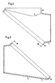
- the shell parts (4, 5) - shown separately in FIGS. 2 and 3 - are connected to one another by an all-round weld seam.
- a handwheel (6) forms the upper end of the valve.
- the upper shell part (4) and the lower shell part (5) are essentially formed by the lateral surfaces of two rule stumps (7) which are bevelled on the larger diameter and which seamlessly merge into a cylindrical region (8) in the region of the bevel.
- the truncated cone is the simplest form of the shell part. However, modifications derived from the truncated cone are also possible.
- the upper shell part (4) is also provided with a recessed opening (9) for connection to the housing attachment (2).
- Both shell parts (4, 5) are provided with a cylindrical recalibration in the area (8).
- the recalibration could also be conical or spherical.
- the housing according to the invention is suitable for different types of fittings. It can be used, for example, for a valve with a conical, cylindrical or flat closure piece, for a slide or a check valve.
Landscapes
- Engineering & Computer Science (AREA)
- General Engineering & Computer Science (AREA)
- Mechanical Engineering (AREA)
- Valve Housings (AREA)
- Telephone Set Structure (AREA)
- Supports Or Holders For Household Use (AREA)
- Packages (AREA)
- Lift Valve (AREA)
- Superconductors And Manufacturing Methods Therefor (AREA)
- Check Valves (AREA)
- Magnetically Actuated Valves (AREA)
Description
- Die Erfindung betrifft ein Armaturengehäuse gemäß dem Oberbegriff des Anspruches 1.
- Ein Blechschalengehäuse für Absperrschieber ist bekannt durch die DE-B 15 50 613. Die Gehäuseschalen dieser bekannten Ausführung werden derart aufgeklappt aus Blech gepreßt, daß sie am Gehäuseboden nahtlos ineinander übergehen. Nach dem Pressen werden die Gehäuseschalen um die Längsachse des Gehäusedurchganges gegeneinander hochgebogen und an den Stoßkanten miteinander verschweißt. Mit Hilfe einer solchen Fertigungsmethode läßt sich zwar die nachteilige Schweißnaht im Gehäuseboden vermeiden; wegen des zusätzlichen Biegevorganges ist dieses Verfahren aber sehr aufwendig.
- Es ist auch bereits bekannt, ein aus Halbkugelschalen zusammengesetztes Armaturengehäuse so zu gestalten, daß die die beiden Schalenteile miteinander verbindende Schweißnaht in einer die Quer- und die Längsachse der Armatur schneidenden Ebene verläuft (Technische Rundschau Sulzer 2/1973). Die Schweißnaht dieses bekannten, einem Niederdruckregelventil zugeordneten Gehäuses lauft ohne Unterbrechung und ohne Kreuzung mit einer anderen Schweißnaht rund um das gesamte Gehäuse. Über die Verbindung der Gehäuseschalen hinaus übernimmt diese Schweißnaht auch die Befestigung eines den Armaturensitz tragenden Teiles. Diese aus schweißtechnischer Sicht vorteilhafte Gehäusegestaltung fand in ähnlicher Form bei einem Kügelhahngehäuse Anwendung (DE-B 23 47 825).
- Die in den vorbekannten Armaturengehäusen verwendeten Halbkugelschalen bilden nur den Gehäusemittelteil, der noch der seitlichen Ergänzung durch Rohrstutzen bedarf. Für diese Rohrstutzen, die für die Verbindung mit einer Rohrleitung mit einem Flansch ausgestattet oder als Einschweißstutzen ausgebildet sind, müssen zwei zusätzliche Schweißnähte vorgesehen werden. Weitere Schweißnähte ergeben sich, wenn ein Gehäuseaufsatz oder ein Zwischenboden zur Vervollstandigung der Armatur notwendig sein sollten.
- Der Erfindung liegt die Aufgabe zugrunde, ein Armaturengehäuse aus Blech zu schaffen, das bei einer Eignung für verschiedene Arten von Absperrarmaturen und einer günstigen Strömungsführung mit einer geringen Anzahl von Schweißnähten herstellbar ist.
- Die Aufgabe wird erfindungsgemäß gelöst durch ein Armaturengehäuse mit den im Anspruch 1 genannten Merkmalen. Die Unteransprüche nennen vorteilhafte Ausgestaltungen des erfindungsgemäßen Armaturengehäuses.
- Anhand eines Ausführungsbeispiels wird die Erfindung näher erläutert. Die Zeichnung zeigt in
- Fig. 1 die Seitenansicht eines Armaturengehäuses, in
- Fig. 2 die obere Hälfte des Hauptteils des in der Fig. 1 dargestellten Armaturengehäuses in Schnittdarstellung und in
- Fig. 3 die untere Hälfte des Gehäusehauptteils in Schnitt darstellung.
- Das im wesentlichen aus einem Hauptteil (1) und einem Gehäuseaufsatz (2) bestehende Armaturengehäuse ist mit angeschweißten Flanschen (3) versehen. Der Hauptteil (1) wird gebildet durch zwei Schalenteile (4, 5). Durch eine rundum laufende Schweißnaht sind die - in den Fig. 2 und 3 gesondert dargestellten - Schalenteile (4, 5) miteinander verbunden. Ein Handrad (6) bildet den oberen Abschluß der Armatur.
- Das obere Schalenteil (4) und das untere Schalenteil (5) werden im wesentlichen gebildet durch die Mantelflächen zweier am größeren Durchmesser abgeschrägter Regelstümpfe (7), die im Bereich der Abschrägung nahtlos übergehen in einen zylindrischen Bereich (8). Der Kegelstumpf bildet die einfachste Form des Schalenteils. Es sind aber auch vom Kegelstumpf abgeleitete Modifikationen möglich.
- Das obere Schalenteil (4) ist noch mit einer ausgehalsten öffnung (9) zur Verbindung mit dem Gehäuseaufsatz (2) versehen. Beide Schalenteile (4, 5) sind im Bereich (8) mit einer zylindrischen Nachkalibrierung versehen. Die Nachkalibrierung könnte auch kegelig oder kugelig sein. Das erfindungsgemäße Gehäuse ist für verschiedene Armaturenarten geeignet. Es ist beispielsweise verwendbar für ein Ventil mit kegeligem, zylindrischem oder flachem Verschlußstück, für einen Schieber oder eine Rückschlagarmatur.
Claims (3)
- Armaturengehäuse aus Blech, dessen Hauptteil aus zwei Schalenteilen besteht, die in einer die Quer- und die Längsachse der Armatur schneidenden Ebene unter Einschluß eines den Armaturensitz tragenden Teiles durch eine nicht unterbrochene Schweißnaht miteinander verbunden sind, dadurch gekennzeichnet, daß die Schalenteile (4, 5) jeweils gebildet werden aus der Mantelfläche eines am größeren Durchmesser abgeschrägten kegelstumpfartigen Körpers (7), der im Bereich der Abschrägung nahtlos übergeht in einen kurzen rotationssymmetrischen, insbesondere zylindrischen Bereich (8), dessen Mittelachse in einem Winkel zur Mittelachse des kegelstumpfartigen Körpers (7) verläuft und dessen Stirnseite der Schweißverbindung mit dem gegenüberliegenden Schalenteil (4, 5) dient.
- Armaturengehäuse nach Anspruch 1, dadurch gekennzeichnet, daß das obere Schalenteil (4) mit einer zylindrisch ausgehalsten Öffnung (9) versehen ist, auf welcher ein Gehäuseaufsatz (2) mit einer nicht unterbrochenen Schweißnaht befestigt ist.
- Armaturengehäuse nach Anspruch 1, dadurch gekennzeichnet, daß die Schalenteile (4, 5) im rotationssymmetrischen Bereich (8) mit einer senkrecht zu der der Schweißverbindung dienenden Stirnseite verlaufenden Nachkalibrierung versehen sind.
Applications Claiming Priority (2)
| Application Number | Priority Date | Filing Date | Title |
|---|---|---|---|
| DE3901698 | 1989-01-21 | ||
| DE3901698A DE3901698A1 (de) | 1989-01-21 | 1989-01-21 | Armaturengehaeuse aus blech |
Publications (2)
| Publication Number | Publication Date |
|---|---|
| EP0454747A1 EP0454747A1 (de) | 1991-11-06 |
| EP0454747B1 true EP0454747B1 (de) | 1992-09-09 |
Family
ID=6372497
Family Applications (1)
| Application Number | Title | Priority Date | Filing Date |
|---|---|---|---|
| EP90902237A Expired - Lifetime EP0454747B1 (de) | 1989-01-21 | 1990-01-09 | Armaturengehäuse aus blech |
Country Status (7)
| Country | Link |
|---|---|
| US (1) | US5188339A (de) |
| EP (1) | EP0454747B1 (de) |
| AT (1) | ATE80447T1 (de) |
| DE (2) | DE3901698A1 (de) |
| DK (1) | DK0454747T3 (de) |
| ES (1) | ES2023040A6 (de) |
| WO (1) | WO1990008280A1 (de) |
Families Citing this family (5)
| Publication number | Priority date | Publication date | Assignee | Title |
|---|---|---|---|---|
| US5370354A (en) * | 1994-04-01 | 1994-12-06 | Emerson Electric Co. | Hermetic solenoid operated valve structure and method of manufacturing the same |
| DE19713370C2 (de) * | 1997-03-29 | 1999-03-11 | Schenke Rolf Joachim | Armaturengehäuse |
| DE20308972U1 (de) | 2003-06-10 | 2003-08-21 | Bürkert Werke GmbH & Co KG, 74653 Ingelfingen | Kleinventil in Blechbauweise |
| PL375246A1 (pl) * | 2005-05-20 | 2006-11-27 | Zakład Urządzeń Gazowniczych Gazomet Spółka Z Ograniczoną Odpowiedzialnością | Korpus kurka, zwłaszcza kurka kulowego |
| JP5032109B2 (ja) * | 2006-12-27 | 2012-09-26 | 株式会社ツカサ | 粉粒体移送用流路切換装置 |
Citations (2)
| Publication number | Priority date | Publication date | Assignee | Title |
|---|---|---|---|---|
| DE1550613B2 (de) * | 1966-12-13 | 1972-09-07 | Westark GmbH Armaturenfabrik, 4620 Ca strop Rauxel | Blechschalengehaeuse fuer absperrschieber |
| DE2347825B2 (de) * | 1973-09-22 | 1976-07-01 | Argus Gesellschaft Mbh, 7505 Ettlingen | Kugelhahn mit gehaeuse in schweissausfuehrung |
Family Cites Families (9)
| Publication number | Priority date | Publication date | Assignee | Title |
|---|---|---|---|---|
| DE638462C (de) * | 1936-11-16 | Aristodemo Emilio Santamaria | Ventilgehaeuse aus durch Schweissung miteinander verbundenen Blechstuecken | |
| DE182974C (de) * | 1906-01-26 | |||
| US1148119A (en) * | 1911-10-24 | 1915-07-27 | Forged Steel Valve Company | Valve. |
| GB522126A (en) * | 1938-02-25 | 1940-06-10 | B R A S A Brevetti Robinetteri | Improvements in the construction of welded valve casings |
| US2869221A (en) * | 1952-10-21 | 1959-01-20 | Stabl Armaturen G M B H | Method of producing valve housings |
| FR1096117A (fr) * | 1954-03-22 | 1955-06-09 | Robinet à corps sphérique | |
| US3630224A (en) * | 1969-10-03 | 1971-12-28 | Charles F Kalvelage | Valve |
| DE3113664A1 (de) * | 1981-04-04 | 1982-10-28 | Westark-Gmbh Armaturenfabrik, 4620 Castrop-Rauxel | Absperrschieber mit einem geschmiedeten oder blechgepressten gehaeuse und eingeschweissten einsatzrohren fuer kraftwerke, insb. kernkraftwerke |
| US4484596A (en) * | 1983-07-25 | 1984-11-27 | Vilter Manufacturing Corporation | Means for securing valve disc to valve spindle |
-
1989
- 1989-01-21 DE DE3901698A patent/DE3901698A1/de not_active Withdrawn
-
1990
- 1990-01-09 DE DE9090902237T patent/DE59000295D1/de not_active Expired - Lifetime
- 1990-01-09 DK DK90902237.8T patent/DK0454747T3/da active
- 1990-01-09 WO PCT/EP1990/000037 patent/WO1990008280A1/de not_active Ceased
- 1990-01-09 US US07/730,864 patent/US5188339A/en not_active Expired - Fee Related
- 1990-01-09 AT AT90902237T patent/ATE80447T1/de not_active IP Right Cessation
- 1990-01-09 EP EP90902237A patent/EP0454747B1/de not_active Expired - Lifetime
- 1990-01-18 ES ES9000149A patent/ES2023040A6/es not_active Expired - Lifetime
Patent Citations (2)
| Publication number | Priority date | Publication date | Assignee | Title |
|---|---|---|---|---|
| DE1550613B2 (de) * | 1966-12-13 | 1972-09-07 | Westark GmbH Armaturenfabrik, 4620 Ca strop Rauxel | Blechschalengehaeuse fuer absperrschieber |
| DE2347825B2 (de) * | 1973-09-22 | 1976-07-01 | Argus Gesellschaft Mbh, 7505 Ettlingen | Kugelhahn mit gehaeuse in schweissausfuehrung |
Non-Patent Citations (1)
| Title |
|---|
| Technische Rundschau Sulzer 2/1973 * |
Also Published As
| Publication number | Publication date |
|---|---|
| DE59000295D1 (de) | 1992-10-15 |
| WO1990008280A1 (de) | 1990-07-26 |
| ES2023040A6 (es) | 1991-12-16 |
| US5188339A (en) | 1993-02-23 |
| ATE80447T1 (de) | 1992-09-15 |
| DK0454747T3 (da) | 1993-01-11 |
| DE3901698A1 (de) | 1990-07-26 |
| EP0454747A1 (de) | 1991-11-06 |
Similar Documents
| Publication | Publication Date | Title |
|---|---|---|
| DE10333721A1 (de) | Kraftstoffverteilerleiste mit einem Anschlussstück | |
| DE2631984A1 (de) | Rohrverschraubung mit anschweisstutzen | |
| EP0454747A1 (de) | Armaturengehäuse aus blech. | |
| EP0217321A2 (de) | Absperrventil | |
| DE10101738A1 (de) | Treibstoffbehälter für Kraftfahrzeuge | |
| DE68901755T2 (de) | Kupplungs- und dichtvorrichtung mit metallippe. | |
| CH685295A5 (de) | Rohrweiche. | |
| EP1317988B1 (de) | Bauteil bei Fahrwerkskomponenten mit einer durch Pressschweissen erzeugten Verbindung | |
| DE3527685A1 (de) | Rohrverbindung an fahrraedern | |
| DE19901990A1 (de) | Pressfitting | |
| EP0454745B1 (de) | Gehäusesitz eines hubventils | |
| DE2120952C3 (de) | Hochdruck-Rückschlagventil | |
| DE8103139U1 (de) | Vorrichtung zum bilden eines abzweigstueckes an einem rohr | |
| DE3036668C2 (de) | Anschlußstutzen für Behälter oder Kessel | |
| DE2947169A1 (de) | Verfahren zur herstellung eines absperrgehaeuses fuer rohrleitungen o.dgl. | |
| EP1132672A2 (de) | Gehäusemittelteil für Ventile | |
| DE2916430A1 (de) | Gesenkgeschmiedetes gehaeuse fuer ein absperr- oder rueckschlagventil | |
| DE4033226A1 (de) | Verfahren zur herstellung eines schaltorgans einer absperr- oder umlenkarmatur und danach hergestelltes schaltorgan | |
| DE4402163A1 (de) | Armaturengehäuse | |
| DE19751138C1 (de) | Winkelstück zur Umlenkung eines Hochdruckleitungsrohres | |
| DE19713370C2 (de) | Armaturengehäuse | |
| DE4342025A1 (de) | Armatur | |
| DE3009456A1 (de) | Kugelgelenkkopf | |
| DE29923950U1 (de) | Zähler für fließfähige Medien | |
| EP4484015A1 (de) | Sprühdüse, anordnung mit einer sprühdüse und verfahren zum herstellen einer sprühdüse |
Legal Events
| Date | Code | Title | Description |
|---|---|---|---|
| PUAI | Public reference made under article 153(3) epc to a published international application that has entered the european phase |
Free format text: ORIGINAL CODE: 0009012 |
|
| 17P | Request for examination filed |
Effective date: 19901227 |
|
| AK | Designated contracting states |
Kind code of ref document: A1 Designated state(s): AT BE CH DE DK FR GB IT LI LU SE |
|
| 17Q | First examination report despatched |
Effective date: 19920303 |
|
| GRAA | (expected) grant |
Free format text: ORIGINAL CODE: 0009210 |
|
| AK | Designated contracting states |
Kind code of ref document: B1 Designated state(s): AT BE CH DE DK FR GB IT LI LU SE |
|
| REF | Corresponds to: |
Ref document number: 80447 Country of ref document: AT Date of ref document: 19920915 Kind code of ref document: T |
|
| RBV | Designated contracting states (corrected) |
Designated state(s): AT BE CH DE DK FR GB IT LI LU NL SE |
|
| REF | Corresponds to: |
Ref document number: 59000295 Country of ref document: DE Date of ref document: 19921015 |
|
| NLXE | Nl: other communications concerning ep-patents (part 3 heading xe) |
Free format text: THE PATENT MENTIONED IN HEADING PE,SECTION 1 IS PUBLISHED DUE TO A RECTIFICATION IN THE EUROPEAN BULLETIN 920930/40 STATING THAT THE PATENT,GRANTED ON 920909,IS ALSO GRANTED FOR THE NETHERLANDS |
|
| ITF | It: translation for a ep patent filed | ||
| ET | Fr: translation filed | ||
| GBT | Gb: translation of ep patent filed (gb section 77(6)(a)/1977) |
Effective date: 19921130 |
|
| REG | Reference to a national code |
Ref country code: DK Ref legal event code: T3 |
|
| PLBE | No opposition filed within time limit |
Free format text: ORIGINAL CODE: 0009261 |
|
| STAA | Information on the status of an ep patent application or granted ep patent |
Free format text: STATUS: NO OPPOSITION FILED WITHIN TIME LIMIT |
|
| 26N | No opposition filed | ||
| EPTA | Lu: last paid annual fee | ||
| PGFP | Annual fee paid to national office [announced via postgrant information from national office to epo] |
Ref country code: GB Payment date: 19941229 Year of fee payment: 6 |
|
| PGFP | Annual fee paid to national office [announced via postgrant information from national office to epo] |
Ref country code: LU Payment date: 19950101 Year of fee payment: 6 |
|
| PGFP | Annual fee paid to national office [announced via postgrant information from national office to epo] |
Ref country code: FR Payment date: 19950103 Year of fee payment: 6 |
|
| PGFP | Annual fee paid to national office [announced via postgrant information from national office to epo] |
Ref country code: BE Payment date: 19950109 Year of fee payment: 6 |
|
| PGFP | Annual fee paid to national office [announced via postgrant information from national office to epo] |
Ref country code: SE Payment date: 19950112 Year of fee payment: 6 Ref country code: DK Payment date: 19950112 Year of fee payment: 6 Ref country code: AT Payment date: 19950112 Year of fee payment: 6 |
|
| PGFP | Annual fee paid to national office [announced via postgrant information from national office to epo] |
Ref country code: DE Payment date: 19950119 Year of fee payment: 6 |
|
| EAL | Se: european patent in force in sweden |
Ref document number: 90902237.8 |
|
| PGFP | Annual fee paid to national office [announced via postgrant information from national office to epo] |
Ref country code: NL Payment date: 19950131 Year of fee payment: 6 |
|
| PGFP | Annual fee paid to national office [announced via postgrant information from national office to epo] |
Ref country code: CH Payment date: 19950223 Year of fee payment: 6 |
|
| PG25 | Lapsed in a contracting state [announced via postgrant information from national office to epo] |
Ref country code: LU Free format text: LAPSE BECAUSE OF NON-PAYMENT OF DUE FEES Effective date: 19960109 Ref country code: GB Effective date: 19960109 Ref country code: DK Effective date: 19960109 Ref country code: AT Effective date: 19960109 |
|
| REG | Reference to a national code |
Ref country code: DK Ref legal event code: EBP |
|
| PG25 | Lapsed in a contracting state [announced via postgrant information from national office to epo] |
Ref country code: SE Effective date: 19960110 |
|
| PG25 | Lapsed in a contracting state [announced via postgrant information from national office to epo] |
Ref country code: LI Effective date: 19960131 Ref country code: CH Effective date: 19960131 Ref country code: BE Effective date: 19960131 |
|
| BERE | Be: lapsed |
Owner name: KSB A.G. Effective date: 19960131 |
|
| PG25 | Lapsed in a contracting state [announced via postgrant information from national office to epo] |
Ref country code: NL Effective date: 19960801 |
|
| GBPC | Gb: european patent ceased through non-payment of renewal fee |
Effective date: 19960109 |
|
| REG | Reference to a national code |
Ref country code: CH Ref legal event code: PL |
|
| PG25 | Lapsed in a contracting state [announced via postgrant information from national office to epo] |
Ref country code: FR Effective date: 19960930 |
|
| NLV4 | Nl: lapsed or anulled due to non-payment of the annual fee |
Effective date: 19960801 |
|
| PG25 | Lapsed in a contracting state [announced via postgrant information from national office to epo] |
Ref country code: DE Effective date: 19961001 |
|
| EUG | Se: european patent has lapsed |
Ref document number: 90902237.8 |
|
| REG | Reference to a national code |
Ref country code: FR Ref legal event code: ST |
|
| PG25 | Lapsed in a contracting state [announced via postgrant information from national office to epo] |
Ref country code: IT Free format text: LAPSE BECAUSE OF NON-PAYMENT OF DUE FEES;WARNING: LAPSES OF ITALIAN PATENTS WITH EFFECTIVE DATE BEFORE 2007 MAY HAVE OCCURRED AT ANY TIME BEFORE 2007. THE CORRECT EFFECTIVE DATE MAY BE DIFFERENT FROM THE ONE RECORDED. Effective date: 20050109 |