EP0454768B1 - Kugelventil - Google Patents
Kugelventil Download PDFInfo
- Publication number
- EP0454768B1 EP0454768B1 EP90902501A EP90902501A EP0454768B1 EP 0454768 B1 EP0454768 B1 EP 0454768B1 EP 90902501 A EP90902501 A EP 90902501A EP 90902501 A EP90902501 A EP 90902501A EP 0454768 B1 EP0454768 B1 EP 0454768B1
- Authority
- EP
- European Patent Office
- Prior art keywords
- ball valve
- stem
- shoulder
- adjacent
- metal
- Prior art date
- Legal status (The legal status is an assumption and is not a legal conclusion. Google has not performed a legal analysis and makes no representation as to the accuracy of the status listed.)
- Expired - Lifetime
Links
Images

Classifications
-
- F—MECHANICAL ENGINEERING; LIGHTING; HEATING; WEAPONS; BLASTING
- F16—ENGINEERING ELEMENTS AND UNITS; GENERAL MEASURES FOR PRODUCING AND MAINTAINING EFFECTIVE FUNCTIONING OF MACHINES OR INSTALLATIONS; THERMAL INSULATION IN GENERAL
- F16K—VALVES; TAPS; COCKS; ACTUATING-FLOATS; DEVICES FOR VENTING OR AERATING
- F16K5/00—Plug valves; Taps or cocks comprising only cut-off apparatus having at least one of the sealing faces shaped as a more or less complete surface of a solid of revolution, the opening and closing movement being predominantly rotary
- F16K5/06—Plug valves; Taps or cocks comprising only cut-off apparatus having at least one of the sealing faces shaped as a more or less complete surface of a solid of revolution, the opening and closing movement being predominantly rotary with plugs having spherical surfaces; Packings therefor
- F16K5/0663—Packings
- F16K5/0694—Spindle sealings
-
- F—MECHANICAL ENGINEERING; LIGHTING; HEATING; WEAPONS; BLASTING
- F16—ENGINEERING ELEMENTS AND UNITS; GENERAL MEASURES FOR PRODUCING AND MAINTAINING EFFECTIVE FUNCTIONING OF MACHINES OR INSTALLATIONS; THERMAL INSULATION IN GENERAL
- F16K—VALVES; TAPS; COCKS; ACTUATING-FLOATS; DEVICES FOR VENTING OR AERATING
- F16K41/00—Spindle sealings
- F16K41/02—Spindle sealings with stuffing-box ; Sealing rings
- F16K41/04—Spindle sealings with stuffing-box ; Sealing rings with at least one ring of rubber or like material between spindle and housing
- F16K41/043—Spindle sealings with stuffing-box ; Sealing rings with at least one ring of rubber or like material between spindle and housing for spindles which only rotate, i.e. non-rising spindles
- F16K41/046—Spindle sealings with stuffing-box ; Sealing rings with at least one ring of rubber or like material between spindle and housing for spindles which only rotate, i.e. non-rising spindles for rotating valves
-
- F—MECHANICAL ENGINEERING; LIGHTING; HEATING; WEAPONS; BLASTING
- F16—ENGINEERING ELEMENTS AND UNITS; GENERAL MEASURES FOR PRODUCING AND MAINTAINING EFFECTIVE FUNCTIONING OF MACHINES OR INSTALLATIONS; THERMAL INSULATION IN GENERAL
- F16K—VALVES; TAPS; COCKS; ACTUATING-FLOATS; DEVICES FOR VENTING OR AERATING
- F16K5/00—Plug valves; Taps or cocks comprising only cut-off apparatus having at least one of the sealing faces shaped as a more or less complete surface of a solid of revolution, the opening and closing movement being predominantly rotary
- F16K5/06—Plug valves; Taps or cocks comprising only cut-off apparatus having at least one of the sealing faces shaped as a more or less complete surface of a solid of revolution, the opening and closing movement being predominantly rotary with plugs having spherical surfaces; Packings therefor
- F16K5/0663—Packings
- F16K5/0668—Single packings
Definitions
- This invention relates to a ball valve and more particularly to an improved metal seat design for a so-called floating ball valve.
- Floating ball valves include a spherical ball valve member mounted within a valve chamber of the valve body for limited floating movement between upstream and downstream seats on opposed sides of the ball valve member.
- a floating ball valve moves in a direction along the longitudinal axis of the flow passages between opposed seats and is limited by such seats to a relatively small predetermined axial movement.
- the object of the invention is to provide a ball valve of the recited type providing improved sealing at both low and high fluid pressures.
- a ball valve having a valve body chamber with a floating ball valve member mounted therein for movement between open and closed positions, and an annular recess about a flow passage in the valve body adjacent the flow chamber defining an outer circumferential surface and an adjacent planar shoulder extending in a generally radial direction; and a one piece annular metal seat fitting within said annular recess about said flow passage adapted for contacting the adjacent spherical surface of the floating ball valve member, whereby that said metal seat comprises a body portion of a generally uniform thickness extending in a generally radial direction in opposed relation to the adjacent planar shoulder and defining an inner low pressure lip about its inner circumference contacting the adjacent spherical surface of the floating ball member in sealing relation during the entire operation of said ball valve; and a bearing portion integrally connected to said body portion and extending therefrom in a direction generally parallel to the longitudinal axis of the flow passage, said bearing portion having a seat adjacent the spherical surface of the floating ball
- a relatively small thickness connecting portion of the seat which extends between the body portion and the bearing portion flexes upon the ball valve member engaging the bearing portion at high pressure conditions and exerts a seating force against the body portion for tightly sealing the rear surface of the body portion against the rear shoulder of the recess in metal-to-metal relation.
- the bearing portion of the metal seat is spaced from the ball valve member a distance less the spacing of the lip from the shoulder of the recess thereby to protect the lip from excessive force exerted by the ball valve member under very high fluid pressures.
- the body portion of the metal seat acts in a manner similar to a Belleville spring and its inner lip provides sealing against the ball valve member at low fluid pressure as low as around 6-8 kPa (1 psi) while spaced from the adjacent shoulder of the recess.
- valve stem mounting means in which aligned openings in the valve body and the outer plate for receiving the stem include an inner packing about the stem and an adjacent Belleville washer exerting a continuous generally uniform compressive loading against the packing.
- valve stem mounting system is disclosed in US-A-2 981 284 according to which the stem has a shoulder between its ends.
- the oppositely facing shoulder surfaces are in engagement with bearing rings fitted in the valve body and a valve body cap, respectively.
- the opening in the outer plate outwardly of the Belleville washer and packing has an outer thrust bearing therein about the stem and is compressed independently of the packing under a predetermined light loading between a stem shoulder and the outer plate by an adjusting nut threaded onto the stem.
- the thrust bearing may be easily inserted or replaced without disassembly of the packing and is not exposed to loading within the valve chamber since mounted outwardly of the packing.
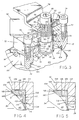
- a spherical plug or ball valve comprising this invention is indicated generally at 10 including a main body portion 14 and an end body portion 12 by a plurality of threaded bolts 16.
- flanges 18 of a flowline 19 fit on opposed ends 20 of body portions 12 and 14 and nut and bolt combination 22 clamp ball valve structure 10 tightly therebetween.
- Body portion 14 has an inlet opening 24 and body portion 12 has an outlet opening 26.
- An inlet flow passage is indicated at 28 and an outlet flow passage is indicated at 30.
- Body portions 12 and 14 define an enlarged diameter valve chamber at 32 and a ball valve member 34 is mounted within chamber 32 for floating movement.
- a stem generally indicated at 36 has a handle 38 mounted thereon and is adapted to rotate ball valve member 34 between open and closed positions relative to flow line 19.
- Ball valve member 34 has a spherical outer surface 40 and a central bore 42 therethrough which is in axial alignment with the longitudinal axis of flow passages 28 and 30 in open position.
- a slot 44 is provided in the upper surface of ball member 34.
- Stem 36 has a lower end 46 fitting within slot 30 and permitting longitudinal movement of ball member 34 in the closed position thereof. Coacting flats defined by slot 44 and lower end 46 effect rotation of ball member 34 upon rotation of stem 36.
- Stem 36 includes an intermediate large diameter stem section 48 adjacent lower end 46, an intermediate diameter stem section 50 adjacent stem section 48 defining an annular shoulder 52 therebetween a cylindrical threaded section 54 adjacent stem section 50, and an upper end threaded section 56 adjacent cylindrical threaded section 54.
- Upper end threaded section 56 has a pair of opposed planar or flat surfaces 58 connected by arcuate externally threaded surfaces 60.
- Valve body portion 12 has an upper opening or bore receiving valve stem 36 defining a small diameter intermediate portion 62, an intermediate diameter inner portion 64, and an enlarged diameter outer portion 66.
- a flange 68 is formed between intermediate bore portion 64 and large diameter bore portion 66.
- a collar 70 integral with stem 70 is spaced from flange 68 and remains spaced from flange 68 even under the application of high fluid pressures within valve chamber 32.
- an outer clamp plate 72 is secured to body portion by a plurality of threaded bolts 74.
- Plate 72 has a bore therethrough defining an inner large diameter bore portion 78, and an outer small diameter bore portion 80.
- a packing 82 fits within enlarged diameter bore portion 66 of body portion 12 about large diameter stem section 48.
- a follower 84 is positioned over the outer end of packing and a pair of Belleville washers 86 fitting within large diameter bore portion 76 of plate 72 are positioned between follower 84 and plate 72 for continuously exerting a downward or inner force against follower 84.
- Washers 86 have inner marginal portions 87 exerting a downward force on follower 84 and outer marginal portions 89 exerting an opposed force on plate 72 with follower 84 compressing packing 82 between shaft 36 and body portion 12. Washers 86 are of an outer diameter substantially larger than the outer diameter of packing 82 and exert a pressure on packing 82 greater than the maximum pressure within valve chamber 32 thereby to provide an inner compressive force against packing 82 at all times.
- a thrust ring 88 is mounted within intermediate bore portion 78 of plate 72 and fits against shoulder 52.
- Thrust ring 88 may be formed of a suitable plastic material, such as polytetrafluoroethylene, which will melt or sublimate at a temperature of about 370°C (700°F).
- a nut 90 is threaded onto stem 36 over plate 72 for maintaining a predetermined relationship between thrust ring 88 and shoulder 52. Since stem 36 is rotated relative to thrust ring 88, a relative light loading of thrust ring 88 is normally provided.
- a stop plate 92 had a generally rectangular opening 94 thereon which receives stem 36 and rotates with stem 36 with plate 58 of stem 36.
- a suitable washer 98 and spacer fit over handle 38 and a securing bolt 99 is threaded within an internally threaded opening in the extending end of stem 36 for securing handle 38 thereon.
- Stop plate 92 engages bolts 74 at the fully open and fully closed positions of ball valve member 34.
- Follower 84 exerts a continuously and generally uniform loading against packing 82 even in the event of wear on packing 82 as a result of the force exerted by Belleville springs 86.
- Thrust ring 88 is positioned outwardly of packing 82 and thus controls the position of stem 36 independently of the force applied to packing 82 by Belleville spring 86. Further, thrust ring 88 limits the outward movement of stem 36 upon high fluid pressures in valve chamber 32 and prevents contact of collar 70 with flange 68. However, when thrust ring 88 is consumed by high temperatures, such as may be generated by a fire or the like, stem 36 may be moved upwardly by high pressure within valve chamber 32 with stem collar 70 contacting flange 68.
- Cap screws 74 hold plate 72 tightly against body portion 12 and nut 90 is lightly tightened for providing the desired frictional contact between shoulder 52 and thrust ring 88 upon rotation of ball valve member 34 between open and closed positions.
- the compressive loading of thrust ring 88 can be increased independently of and without compressing packing 82.
- thrust ring 88 can easily be inserted or replaced without removal of packing 82 and is not exposed to ladings within valve chamber 32 which might be corrosive.
- Recesses 100 adjacent valve chamber 32 are provided in the valve body about inlet flow passage 28 and outlet flow passage 30.
- An annular upstream metal seat 102 is mounted in recess 100 about inlet flow passage 28 and an annular downstream metal seat 104 is mounted in recess 100 about outlet flow passage 30.
- Recesses 100 and seats 102, 104 are generally identical and for the purpose of illustration, only the downstream seat 104 is described in detail as shown in Figures 4 and 5.
- recess 110 is defined by an outer peripheral surface 106 which extends in a concentric relation to the longitudinal axis of the associated flow passage and a radial planar surface 108 forms a shoulder extending perpendicularly to surface 106.
- Metal seat 104 of a one-piece metal construction fits within recess 100 adjacent surfaces 106, 108 and comprises a body portion 110 of a generally uniform thickness T between generally parallel planar surfaces 112 and 113 which extend in a generally radial direction.
- Rear planar surface 112 provides a sealing surface against shoulder 108 which at low fluid pressure seals generally at the corner of recess 100 as shown in Figure 4, but at high fluid pressure seals along substantially the entire face of shoulder 108 as shown in Figure 5.
- Body portion 110 acts in a manner similar to a Belleville spring and has a flexible lip 114 at its inner circumference which is rounded at 116 for engaging spherical surface 40 of ball valve member 34. Lip 114 is spaced a distance D from the opposed shoulder 108 during normal operation in the open position of valve member 34 and during low fluid pressure operation in the closed position of ball valve member 34.
- a high pressure flexible seat or bearing portion 118 of metal seat 104 is connected to body portion 110 and has an arcuate bearing or sealing surface 120 adapted to engage adjacent spherical surface 40 of ball valve member 34 under high fluid pressure conditions.
- Seat portion 118 has an outer circumferential surface 122 in opposed relation to outer periphery 106 and arcuate sealing surface 120 is of a contour generally the same as the adjacent spherical surface 40 of ball valve member 34.
- ball valve member 34 is spaced a distance D1 from bearing surface 120 in axial direction parallel to the longitudinal axis of flow passages 28 and 30 as shown in Figure 4.
- Distance D1 under all conditions of operation is less than distance D to act as a stop for ball valve member 34 to minimize wear or damage to lip 114 in forcing lip 114 against shoulder 108.
- D1 may be 0.127mm (.005 inch) and D may be 0.2mm (.008 inch). In any event, D would be at least 0.025mm (.001 inch) greater than D1.
- An outer annular groove 126 in seat 34 defines a connecting portion 128 of seat 34 extending between bearing portion 104 and body portion 110 in a direction generally parallel to the longitudinal axis of the flow passages 28 and 30.
- Connecting portion 128 is flexible and preferably has a generally uniform thickness T1 between around 25% and 65% of the thickness T of body portion 110 with an optimum thickness of around 45% of thickness T.
- connecting portion 128 flexes but yet has sufficient rigidity to exert a strong force against body portion 110 for urging rear sealing surface 112 into tight sealing relation against shoulder 108.
- rounded end 116 is in substantially line contact relation with spherical surface 40 of ball valve member 34 with lip 114 spaced a distance D from adjacent recess shoulder 108, and bearing surface 120 is spaced a distance D1 from the adjacent spherical surface 40 of ball valve member 34.
- Body portion 110 is in metal-to-metal sealing relation with shoulder 108 adjacent the corner of recess 100 formed at the juncture of shoulder 108 with outer circumferential surface 106.
- Metal seal 104 may be formed of various types of corrosion resistant metallic materials, such as a titanium, for example, which has a modulus of elasticity of around 10.3 x 10¹⁰ Pa (15 million psi).
- metal seat 104 while of a substantial strength is relatively flexible in a radial direction between lip 114 and seat portion 118 and will seal adequately even with substantial manufacturing tolerances in shoulder 108 and outer peripheral surface 106 of recess 100.
- bearing surface 120 is contacted by ball valve member 34 before lip 114 engages shoulder 108 to restrain the force exerted against low pressure lip 114 by ball valve member 34.
- Connecting portion 128 transmits the force to body portion 110 for providing a tight sealing force which increases in relation to an increase in fluid pressure.
- Metal seat 104 is particularly adapted for fitting within a recess defined by a pair of body surfaces at right angles to each other.
- a secondary stem seal is provided by collar 70 against flange 68 when high temperature consumes or deteriorates thrust bearing or ring 88 as internal pressure acting against stem 36 forces collar 70 against flange 68 to provide metal to metal engagement.
Landscapes
- Engineering & Computer Science (AREA)
- General Engineering & Computer Science (AREA)
- Mechanical Engineering (AREA)
- Taps Or Cocks (AREA)
- External Artificial Organs (AREA)
- Fuel-Injection Apparatus (AREA)
- Temperature-Responsive Valves (AREA)
- Float Valves (AREA)
Claims (9)
- Kugelventil mit einer Ventilkammer (32), mit einer schwimmenden Ventilkugel (34), welche in dieser montiert ist, um sich zwischen der geöffneten und geschlossenen Position zu bewegen, und mit einer ringförmigen Vertiefung (100) um eine Durchflussöffnung (28, 30) im Ventilgehäuse (14) bei der Ventilkammer (32), welche eine äussere Umfangsfläche (106) und eine angrenzende, ebene Schulter (108) aufweist, welche sich in einer im allgemeinen radialen Richtung erstreckt; und mit einem ringförmigen metallischen Sitz (102, 104), welcher in die ringförmige Vertiefung (100), um die Durchflussöffnung passt und ausgebildet ist, um die angrenzende Kugeloberfläche (40) der schwimmenden Ventilkugel (34) zu berühren, dadurch gekennzeichnet, dass der metallische Sitz (102, 104) einen Teil (110) aufweist, der in radialer Richtung, der ebenen Schulter (108) gegenüberliegend, eine im grossen und ganzen gleichbleibende Dicke aufweist und dabei eine innere Lippe (114) für niedrigen Druck um die angrenzende Kugeloberfläche (40) der Ventilkugel (34) bildet, welche während dem ganzen Betrieb des Kugelventils mit dieser im Dichtkontakt ist; und mit einem Lager (118), welches mit dem Gehäuseteil zusammenhängt und sich davon in einer Richtung erstreckt, die im wesentlichen parallel zur Längsachse des Durchflusses (28, 30) ist, wobei der Lagerteil (118) einen Sitz (120) aufweist, der an die Kugeloberfläche (40) der schwimmenden Ventilkugel (34) grenzt, wobei der Sitz bei niedrigem Druck im Kugelventil von der Kugeloberfläche (40) einen Abstand hat und die Kugeloberfläche bei hohem Druck im Kugelventil auf dem Sitz lagert.
- Kugelventil nach Anspruch 1, dadurch gekennzeichnet, dass der Teil (110) des metallischen Sitzes (102, 104) im wesentlichen mit der Lippe (114), welche in einem Abstand zur Schulter (108) angeordnet ist, bei niedrigem Druck gleich wie ein Belleville Federring arbeitet und der Teil (110) mit der Schulter (108) die an die Ecke der Vertiefung (100) angrenzt, entlang der Berührungslinie der Schulter (108) der äusseren Umfangsfläche (106) einen metallischen Kontakt bildet.
- Kugelventil nach Anspruch 2, dadurch gekennzeichnet, dass die Lippe (114) einen Abstand zur Schulter (108) hat, der kleiner ist als der Abstand der Ventilkugel (34) vom Lager (118) in Richtung parallel zur Längsachse des Durchflusses (28, 30), so dass das Lager (118) von der Ventilkugel (34) berührt wird, bevor die Lippe (114) die Schulter (108) berührt.
- Kugelventil nach Anspruch 1, dadurch gekennzeichnet, dass der metallische Sitz (102, 104) einen Verbindungsteil (128) zwischen dem Lager (118) und dem Teil (110) aufweist, der sich in einer Richtung parallel zur Längsachse des Durchflusses (102, 104) erstreckt, wobei der Verbindungsteil (128) eine geringere Dicke hat als der Teil (110).
- Kugelventil nach Anspruch 4, dadurch gekennzeichnet, dass der Verbindungsteil (128) eine weitgehend gleichmässige Dicke, von zwischen etwa 25 % und 65 % der Dicke des Teils (110) aufweist.
- Kugelventil nach Anspruch 5 dadurch gekennzeichnet, dass der metallische Sitz (102, 104) eine äussere ringförmige Nute (126) um seinem äusseren Umfangteil (118) und um den Teil (110) aufweist, wobei der Verbindungsteil (128) den Boden der Nute (126) bildet.
- Kugelventil nach Anspruch 1, gekennzeichnet durch einen Schaft (36), der mit der Ventilkugel (34) verbunden ist, um die Ventilkugel (34) zwischen der offenen und der geschlossenen Stellung zu drehen, und durch eine äussere Dichtplatte (72) im Ventilgehäuse (14) welche den Schaft (36) auf dem Ventilgehäuse (14) verbindet und der durch Öffnungen verläuft, welche durch ausgerichtete Öffnungen im Ventilgehäuse (14) und in der Platte (72) verläuft, und durch Mittel für die Montage des Schafts, welche eine Dichtung (82) umfassen, welche in der Öffnung im Gehäuse (14), um den Schaft (36) angeordnet ist, und mit einem Aufhalter (84) der gegen das äussere Ende der Packung (82) stösst, einem Belleville Federring (86) der zwischen den ausgerichteten Öffnungen in der äusseren Platte (72) um den Schaft (36) angeordnet ist und gegen die äussere Platte (72) und den Aufhalter (84) drückt, um ständig einen Druck gegen die Dichtung (82) auszuüben, und mit einem Schubring (88), der in der ausgerichteten Öffnung in der äusseren Platte (72) an einer Stelle ausserhalb des Belleville Federrings (86) zwischen sich gegenüberliegenden Oberflächen des Schafts (36) und der Platte (72) angeordnet ist und der sich senkrecht zur Rotationsachse des Schafts (72) erstreckt; und einer Einstellmutter (90) welche ausserhalb der Platte (72) auf den Schaft (36) geschraubt ist, um die sich gegenüberliegenden Oberflächen gegeneinander zu drücken um eine vorgegebene Kraft auf das Drucklager (88) auszuüben.
- Kugelventil nach Anspruch 7, dadurch gekennzeichnet, dass die ausgerichtete Öffnung in der äusseren Platte (72) einen inneren Teil (76) mit einem grossen Durchmesser aufweist, welcher den Belleville Federring (86) stützt und einen daran angrenzenden Teil (78) mit einem mittleren Durchmesser, welcher den Schubring (88) stützt; und der Schaft (36) eine ringförmige Schulter (52) aufweist, welche die eine der sich gegenüberliegenden Oberflächen bildet, auf der sich der Schubring (88) abstützt.
- Kugelventil nach Anspruch 7, dadurch gekennzeichnet, dass der Schubring (88) aus einem Werkstoff besteht, der sich bei hoher Temperatur zersetzt, und der Schaft (38) einen Kragen (70) mit grösserem Durchmesser aufweist, welcher der Ventilkammer (32) ausgesetzt ist und der sich unter dem Druck in der Ventilkammer (32) nach oben bewegt, wenn sich der Schubring (88) zersetzt hat und dabei das Ventilgehäuse berührt und mit diesem eine metallische Dichtung bildet.
Priority Applications (1)
| Application Number | Priority Date | Filing Date | Title |
|---|---|---|---|
| EP19930203724 EP0592056A3 (en) | 1989-01-10 | 1990-01-10 | Ball valve |
Applications Claiming Priority (3)
| Application Number | Priority Date | Filing Date | Title |
|---|---|---|---|
| US295744 | 1989-01-10 | ||
| US07/295,744 US4899980A (en) | 1989-01-10 | 1989-01-10 | Ball valve |
| PCT/US1990/000165 WO1990008278A1 (en) | 1989-01-10 | 1990-01-10 | Ball valve |
Related Child Applications (1)
| Application Number | Title | Priority Date | Filing Date |
|---|---|---|---|
| EP93203724.5 Division-Into | 1993-12-30 |
Publications (3)
| Publication Number | Publication Date |
|---|---|
| EP0454768A1 EP0454768A1 (de) | 1991-11-06 |
| EP0454768A4 EP0454768A4 (en) | 1992-05-13 |
| EP0454768B1 true EP0454768B1 (de) | 1994-07-27 |
Family
ID=23139068
Family Applications (2)
| Application Number | Title | Priority Date | Filing Date |
|---|---|---|---|
| EP19930203724 Withdrawn EP0592056A3 (en) | 1989-01-10 | 1990-01-10 | Ball valve |
| EP90902501A Expired - Lifetime EP0454768B1 (de) | 1989-01-10 | 1990-01-10 | Kugelventil |
Family Applications Before (1)
| Application Number | Title | Priority Date | Filing Date |
|---|---|---|---|
| EP19930203724 Withdrawn EP0592056A3 (en) | 1989-01-10 | 1990-01-10 | Ball valve |
Country Status (8)
| Country | Link |
|---|---|
| US (1) | US4899980A (de) |
| EP (2) | EP0592056A3 (de) |
| JP (1) | JPH04502803A (de) |
| AT (1) | ATE109259T1 (de) |
| CA (1) | CA2045596C (de) |
| DE (1) | DE69011090T2 (de) |
| ES (1) | ES2057535T3 (de) |
| WO (1) | WO1990008278A1 (de) |
Families Citing this family (19)
| Publication number | Priority date | Publication date | Assignee | Title |
|---|---|---|---|---|
| US5088687A (en) * | 1990-09-19 | 1992-02-18 | Stender Carl H | Ball valve seat for high temperature service |
| US6698712B2 (en) | 2002-05-02 | 2004-03-02 | Dril-Quip, Inc. | Ball valve assembly |
| US6988708B2 (en) * | 2003-10-06 | 2006-01-24 | Dresser, Inc. | Low torque ball valve seat |
| US7195225B1 (en) | 2003-10-30 | 2007-03-27 | Dril-Quip, Inc. | Rotary valve assembly |
| US7726339B2 (en) * | 2006-01-14 | 2010-06-01 | Dresser, Inc. | Seal cartridge control valve |
| US8424841B2 (en) * | 2009-03-16 | 2013-04-23 | Bray International, Inc. | Multi-component metal seat design for ball valves |
| IT1398767B1 (it) * | 2010-03-03 | 2013-03-18 | Tyco Valves & Controls Italia S R L | Seggio metallico di valvole di intercettazione fluido |
| WO2011112073A1 (en) * | 2010-03-08 | 2011-09-15 | Indufil B.V. | Ball valve |
| US8607882B2 (en) * | 2011-04-27 | 2013-12-17 | Halliburton Energy Services, Inc. | Load balancing spherical diameter single seat ball system |
| BR112015017036A2 (pt) | 2013-02-25 | 2017-07-11 | Halliburton Energy Services Inc | válvula de esfera e método |
| WO2015099787A1 (en) | 2013-12-27 | 2015-07-02 | Halliburton Energy Services Inc. | Ball valve having dual pistons each individually actuable |
| WO2016007127A1 (en) | 2014-07-07 | 2016-01-14 | Flowserve Management Company | Valve assemblies, valve seats including flexible arms, and related methods |
| ITUA20162716A1 (it) * | 2016-04-19 | 2017-10-19 | Truflo Rona | Dispositivo di tenuta per lo stelo di una valvola |
| KR101825220B1 (ko) * | 2017-08-07 | 2018-02-02 | (주)케이에스티플랜트 | 마이크로합금화 층이 형성된 메탈시트 볼밸브 장치 및 그 제작 방법 |
| FR3081200B1 (fr) * | 2018-05-18 | 2021-07-23 | Sogefi Air & Cooling | Joint d'etancheite, notamment pour une vanne a boisseau spherique rotatif |
| EP4102115B1 (de) * | 2021-06-11 | 2024-11-13 | Illinois Tool Works Inc. | Dichtung und ventilvorrichtung mit einer solchen dichtung, sowie verfahren zum abdichten einer ventilvorrichtung |
| CN115264103A (zh) * | 2022-07-12 | 2022-11-01 | 北京市阀门总厂股份有限公司 | 超低温球阀密封圈与阀座间的密封结构及其装配方法 |
| CN115264167B (zh) * | 2022-07-27 | 2025-05-02 | 北京市阀门总厂股份有限公司 | 浮动球阀的阀轴导向密封结构及浮动球阀 |
| WO2024178060A1 (en) * | 2023-02-22 | 2024-08-29 | Bray International, Inc. | Bidirectional one piece metal seat for ball valve |
Citations (3)
| Publication number | Priority date | Publication date | Assignee | Title |
|---|---|---|---|---|
| US2981284A (en) * | 1959-07-24 | 1961-04-25 | J L Putnam Company Inc | Ball valve |
| US3576309A (en) * | 1969-02-19 | 1971-04-27 | Fmc Corp | Top entry ball valve |
| US4745944A (en) * | 1987-10-15 | 1988-05-24 | Francart Jr Armand | Self-cleaning, fluid pressure biased gate valve |
Family Cites Families (18)
| Publication number | Priority date | Publication date | Assignee | Title |
|---|---|---|---|---|
| US474944A (en) * | 1892-05-17 | Process of making paper-pulp | ||
| US2989990A (en) * | 1959-07-09 | 1961-06-27 | Gen Dynamics Corp | Valve |
| US3548858A (en) * | 1965-03-01 | 1970-12-22 | Rockwell Mfg Co | Seat ring for plug valve |
| US3386669A (en) * | 1966-04-25 | 1968-06-04 | Borden Co | Ore slurry handling apparatus |
| FR1517729A (fr) * | 1966-07-05 | 1968-03-22 | Joint perfectionné pour vannes ou robinets à boule | |
| NL164942C (nl) * | 1975-09-25 | Kitazawa Shoji Kk | Plugkraan. | |
| FR2476791A1 (fr) * | 1980-02-22 | 1981-08-28 | Jgc Corp | Soupape du type a cartouche pour remplacer rapidement la tete et le siege de la soupape |
| DE3263656D1 (en) * | 1981-06-13 | 1985-06-13 | Klinger Ag | Ball valve |
| US4385747A (en) * | 1982-01-07 | 1983-05-31 | Worcester Controls Corporation | Self-relieving seat and ball valve incorporating the same |
| JPS58104462U (ja) * | 1982-01-09 | 1983-07-15 | 株式会社北沢バルブ | プレツシヤ−リリ−フ機能を有するボ−ルバルブの弁座 |
| DE3239977A1 (de) * | 1982-10-28 | 1984-05-03 | Fritz Voltz Sohn Gmbh & Co, 6000 Frankfurt | Kugel- oder kegelhahn |
| US4558874A (en) * | 1983-07-05 | 1985-12-17 | Whitey Co. | Valve stem packing assembly |
| US4580763A (en) * | 1984-01-26 | 1986-04-08 | Velan, Inc. | Seal-seat for use in ball valves |
| DE3425557A1 (de) * | 1984-07-11 | 1986-01-16 | Chemat GmbH Armaturen für Industrie- und Nuklearanlagen, 7592 Renchen | Stopfbuchsmutter mit integriertem federelement |
| US4579316A (en) * | 1984-11-26 | 1986-04-01 | Velan Inc. | Metal seated ball valves |
| US4696323A (en) * | 1985-08-30 | 1987-09-29 | Neotecha Ag | Plastic lined rotatable valve |
| FI72584C (fi) * | 1985-09-04 | 1987-06-08 | Neles Oy | Ventil. |
| GB8620489D0 (en) * | 1986-08-22 | 1986-10-01 | Nicholson T P | Rotary ball valves & joints |
-
1989
- 1989-01-10 US US07/295,744 patent/US4899980A/en not_active Expired - Lifetime
-
1990
- 1990-01-10 ES ES90902501T patent/ES2057535T3/es not_active Expired - Lifetime
- 1990-01-10 CA CA002045596A patent/CA2045596C/en not_active Expired - Fee Related
- 1990-01-10 WO PCT/US1990/000165 patent/WO1990008278A1/en not_active Ceased
- 1990-01-10 DE DE69011090T patent/DE69011090T2/de not_active Expired - Fee Related
- 1990-01-10 AT AT90902501T patent/ATE109259T1/de not_active IP Right Cessation
- 1990-01-10 EP EP19930203724 patent/EP0592056A3/en not_active Withdrawn
- 1990-01-10 EP EP90902501A patent/EP0454768B1/de not_active Expired - Lifetime
- 1990-01-10 JP JP2502831A patent/JPH04502803A/ja active Pending
Patent Citations (3)
| Publication number | Priority date | Publication date | Assignee | Title |
|---|---|---|---|---|
| US2981284A (en) * | 1959-07-24 | 1961-04-25 | J L Putnam Company Inc | Ball valve |
| US3576309A (en) * | 1969-02-19 | 1971-04-27 | Fmc Corp | Top entry ball valve |
| US4745944A (en) * | 1987-10-15 | 1988-05-24 | Francart Jr Armand | Self-cleaning, fluid pressure biased gate valve |
Also Published As
| Publication number | Publication date |
|---|---|
| EP0592056A3 (en) | 1994-05-18 |
| WO1990008278A1 (en) | 1990-07-26 |
| EP0454768A4 (en) | 1992-05-13 |
| ES2057535T3 (es) | 1994-10-16 |
| DE69011090D1 (de) | 1994-09-01 |
| US4899980A (en) | 1990-02-13 |
| CA2045596C (en) | 2000-08-01 |
| DE69011090T2 (de) | 1994-12-01 |
| CA2045596A1 (en) | 1990-07-11 |
| ATE109259T1 (de) | 1994-08-15 |
| JPH04502803A (ja) | 1992-05-21 |
| EP0592056A2 (de) | 1994-04-13 |
| EP0454768A1 (de) | 1991-11-06 |
Similar Documents
| Publication | Publication Date | Title |
|---|---|---|
| US4940208A (en) | Ball valve | |
| EP0454768B1 (de) | Kugelventil | |
| EP0004428B1 (de) | Kugelküken und Hahn mit ausbaubarem Kugelküken und Sitzen für hohe Temperaturen | |
| FI74336B (fi) | Excentrisk ventil med sjaelvcentrerande saete. | |
| US4558874A (en) | Valve stem packing assembly | |
| US3894718A (en) | Ball valve | |
| JP2740154B2 (ja) | 閉止弁向けのステム先端のシール構造体 | |
| US4796858A (en) | Dual seal valve | |
| EP0123421B1 (de) | Ventilspindelabdichtung | |
| US4750709A (en) | Diaphragm valve | |
| US4293116A (en) | Metallic seat assembly for valves | |
| US4290581A (en) | Seat assembly for ball valves | |
| US7093819B1 (en) | Ball valve with shear bushing and integral bracket for stem blowout protection | |
| US5064167A (en) | Adjustable packing assembly for valve stem | |
| JPH04285371A (ja) | 回転弁の閉鎖シール装置、その製造方法及び回転弁の製造方法 | |
| EP0060620B1 (de) | Feuerfester Sitz für ein Ventil | |
| US5181690A (en) | Shut-off valve | |
| EP0110012B1 (de) | Ventileinheit | |
| US6079695A (en) | Butterfly valve construction | |
| US4580763A (en) | Seal-seat for use in ball valves | |
| EP0124234B1 (de) | Schieber | |
| EP0013265B1 (de) | Ventilsitzanordnung für Hochtemperaturventile und Anwendung in Klappenventile | |
| EP0401443A1 (de) | Kugelventil mit kleinem Drehmoment | |
| CA1208191A (en) | Bidirectional valve seal | |
| US6651958B1 (en) | Valve seat having a frusto-conical shape |
Legal Events
| Date | Code | Title | Description |
|---|---|---|---|
| PUAI | Public reference made under article 153(3) epc to a published international application that has entered the european phase |
Free format text: ORIGINAL CODE: 0009012 |
|
| 17P | Request for examination filed |
Effective date: 19901205 |
|
| AK | Designated contracting states |
Kind code of ref document: A1 Designated state(s): AT BE CH DE DK ES FR GB IT LI LU NL SE |
|
| A4 | Supplementary search report drawn up and despatched |
Effective date: 19920326 |
|
| AK | Designated contracting states |
Kind code of ref document: A4 Designated state(s): AT BE CH DE DK ES FR GB IT LI LU NL SE |
|
| 17Q | First examination report despatched |
Effective date: 19930208 |
|
| GRAA | (expected) grant |
Free format text: ORIGINAL CODE: 0009210 |
|
| AK | Designated contracting states |
Kind code of ref document: B1 Designated state(s): AT BE CH DE DK ES FR GB IT LI LU NL SE |
|
| PG25 | Lapsed in a contracting state [announced via postgrant information from national office to epo] |
Ref country code: LI Effective date: 19940727 Ref country code: DK Effective date: 19940727 Ref country code: CH Effective date: 19940727 Ref country code: AT Effective date: 19940727 |
|
| REF | Corresponds to: |
Ref document number: 109259 Country of ref document: AT Date of ref document: 19940815 Kind code of ref document: T |
|
| XX | Miscellaneous (additional remarks) |
Free format text: TEILANMELDUNG 93203724.5 EINGEREICHT AM 30/12/93. |
|
| REF | Corresponds to: |
Ref document number: 69011090 Country of ref document: DE Date of ref document: 19940901 |
|
| ITF | It: translation for a ep patent filed | ||
| REG | Reference to a national code |
Ref country code: ES Ref legal event code: FG2A Ref document number: 2057535 Country of ref document: ES Kind code of ref document: T3 |
|
| PG25 | Lapsed in a contracting state [announced via postgrant information from national office to epo] |
Ref country code: SE Effective date: 19941027 |
|
| REG | Reference to a national code |
Ref country code: CH Ref legal event code: PL |
|
| ET | Fr: translation filed | ||
| PG25 | Lapsed in a contracting state [announced via postgrant information from national office to epo] |
Ref country code: LU Free format text: LAPSE BECAUSE OF NON-PAYMENT OF DUE FEES Effective date: 19950131 |
|
| PLBE | No opposition filed within time limit |
Free format text: ORIGINAL CODE: 0009261 |
|
| STAA | Information on the status of an ep patent application or granted ep patent |
Free format text: STATUS: NO OPPOSITION FILED WITHIN TIME LIMIT |
|
| 26N | No opposition filed | ||
| PGFP | Annual fee paid to national office [announced via postgrant information from national office to epo] |
Ref country code: ES Payment date: 19960430 Year of fee payment: 7 |
|
| PGFP | Annual fee paid to national office [announced via postgrant information from national office to epo] |
Ref country code: GB Payment date: 19960501 Year of fee payment: 7 |
|
| PGFP | Annual fee paid to national office [announced via postgrant information from national office to epo] |
Ref country code: FR Payment date: 19960510 Year of fee payment: 7 |
|
| PGFP | Annual fee paid to national office [announced via postgrant information from national office to epo] |
Ref country code: DE Payment date: 19960513 Year of fee payment: 7 |
|
| PGFP | Annual fee paid to national office [announced via postgrant information from national office to epo] |
Ref country code: BE Payment date: 19960523 Year of fee payment: 7 |
|
| PGFP | Annual fee paid to national office [announced via postgrant information from national office to epo] |
Ref country code: NL Payment date: 19960529 Year of fee payment: 7 |
|
| PG25 | Lapsed in a contracting state [announced via postgrant information from national office to epo] |
Ref country code: GB Effective date: 19970110 |
|
| PG25 | Lapsed in a contracting state [announced via postgrant information from national office to epo] |
Ref country code: ES Free format text: LAPSE BECAUSE OF NON-PAYMENT OF DUE FEES Effective date: 19970111 |
|
| PG25 | Lapsed in a contracting state [announced via postgrant information from national office to epo] |
Ref country code: BE Effective date: 19970131 |
|
| BERE | Be: lapsed |
Owner name: KEMP DEVELOPMENT CORP. Effective date: 19970131 |
|
| PG25 | Lapsed in a contracting state [announced via postgrant information from national office to epo] |
Ref country code: NL Effective date: 19970801 |
|
| GBPC | Gb: european patent ceased through non-payment of renewal fee |
Effective date: 19970110 |
|
| PG25 | Lapsed in a contracting state [announced via postgrant information from national office to epo] |
Ref country code: FR Effective date: 19970930 |
|
| NLV4 | Nl: lapsed or anulled due to non-payment of the annual fee |
Effective date: 19970801 |
|
| PG25 | Lapsed in a contracting state [announced via postgrant information from national office to epo] |
Ref country code: DE Effective date: 19971001 |
|
| REG | Reference to a national code |
Ref country code: FR Ref legal event code: ST |
|
| REG | Reference to a national code |
Ref country code: ES Ref legal event code: FD2A Effective date: 19990503 |
|
| PG25 | Lapsed in a contracting state [announced via postgrant information from national office to epo] |
Ref country code: IT Free format text: LAPSE BECAUSE OF NON-PAYMENT OF DUE FEES;WARNING: LAPSES OF ITALIAN PATENTS WITH EFFECTIVE DATE BEFORE 2007 MAY HAVE OCCURRED AT ANY TIME BEFORE 2007. THE CORRECT EFFECTIVE DATE MAY BE DIFFERENT FROM THE ONE RECORDED. Effective date: 20050110 |