EP0454788B1 - Mit pedalen angetriebene vom oberschenkel gesteuerte struktur - Google Patents
Mit pedalen angetriebene vom oberschenkel gesteuerte struktur Download PDFInfo
- Publication number
- EP0454788B1 EP0454788B1 EP90903265A EP90903265A EP0454788B1 EP 0454788 B1 EP0454788 B1 EP 0454788B1 EP 90903265 A EP90903265 A EP 90903265A EP 90903265 A EP90903265 A EP 90903265A EP 0454788 B1 EP0454788 B1 EP 0454788B1
- Authority
- EP
- European Patent Office
- Prior art keywords
- pedal
- axle
- strap
- ligatures
- rider
- Prior art date
- Legal status (The legal status is an assumption and is not a legal conclusion. Google has not performed a legal analysis and makes no representation as to the accuracy of the status listed.)
- Expired - Lifetime
Links
- 210000000689 upper leg Anatomy 0.000 title claims abstract description 21
- 210000003127 knee Anatomy 0.000 claims abstract description 8
- 210000002414 leg Anatomy 0.000 description 18
- 210000003205 muscle Anatomy 0.000 description 2
- 239000004677 Nylon Substances 0.000 description 1
- 230000017531 blood circulation Effects 0.000 description 1
- 238000010276 construction Methods 0.000 description 1
- 230000008878 coupling Effects 0.000 description 1
- 238000010168 coupling process Methods 0.000 description 1
- 238000005859 coupling reaction Methods 0.000 description 1
- 230000000694 effects Effects 0.000 description 1
- 210000003414 extremity Anatomy 0.000 description 1
- 239000004744 fabric Substances 0.000 description 1
- 230000003993 interaction Effects 0.000 description 1
- 239000010985 leather Substances 0.000 description 1
- 238000004519 manufacturing process Methods 0.000 description 1
- 239000000463 material Substances 0.000 description 1
- 239000002184 metal Substances 0.000 description 1
- 229920001778 nylon Polymers 0.000 description 1
- 239000004033 plastic Substances 0.000 description 1
- 230000001105 regulatory effect Effects 0.000 description 1
- 230000000284 resting effect Effects 0.000 description 1
- 230000001960 triggered effect Effects 0.000 description 1
Images

Classifications
-
- A—HUMAN NECESSITIES
- A63—SPORTS; GAMES; AMUSEMENTS
- A63B—APPARATUS FOR PHYSICAL TRAINING, GYMNASTICS, SWIMMING, CLIMBING, OR FENCING; BALL GAMES; TRAINING EQUIPMENT
- A63B21/00—Exercising apparatus for developing or strengthening the muscles or joints of the body by working against a counterforce, with or without measuring devices
-
- B—PERFORMING OPERATIONS; TRANSPORTING
- B62—LAND VEHICLES FOR TRAVELLING OTHERWISE THAN ON RAILS
- B62M—RIDER PROPULSION OF WHEELED VEHICLES OR SLEDGES; POWERED PROPULSION OF SLEDGES OR SINGLE-TRACK CYCLES; TRANSMISSIONS SPECIALLY ADAPTED FOR SUCH VEHICLES
- B62M1/00—Rider propulsion of wheeled vehicles
- B62M1/36—Rider propulsion of wheeled vehicles with rotary cranks, e.g. with pedal cranks
-
- B—PERFORMING OPERATIONS; TRANSPORTING
- B62—LAND VEHICLES FOR TRAVELLING OTHERWISE THAN ON RAILS
- B62M—RIDER PROPULSION OF WHEELED VEHICLES OR SLEDGES; POWERED PROPULSION OF SLEDGES OR SINGLE-TRACK CYCLES; TRANSMISSIONS SPECIALLY ADAPTED FOR SUCH VEHICLES
- B62M1/00—Rider propulsion of wheeled vehicles
-
- Y—GENERAL TAGGING OF NEW TECHNOLOGICAL DEVELOPMENTS; GENERAL TAGGING OF CROSS-SECTIONAL TECHNOLOGIES SPANNING OVER SEVERAL SECTIONS OF THE IPC; TECHNICAL SUBJECTS COVERED BY FORMER USPC CROSS-REFERENCE ART COLLECTIONS [XRACs] AND DIGESTS
- Y10—TECHNICAL SUBJECTS COVERED BY FORMER USPC
- Y10T—TECHNICAL SUBJECTS COVERED BY FORMER US CLASSIFICATION
- Y10T74/00—Machine element or mechanism
- Y10T74/21—Elements
- Y10T74/2164—Cranks and pedals
- Y10T74/2168—Pedals
Definitions
- This invention relates to thigh-assisted pedal-powered structures, especially bicycles, in, order to utilize the upward thrust of the thigh to more effectively utilize the strength of the leg in powering the pedal structure.
- the operator will use straps to couple his foot to the pedal so that the pedal will be pulled upwardly as he raises his leg. To a small degree, this helps to increase the power of the operator, but as the pedal is at the extremity of the leg, the raising of the leg by the operator on the upward stroke is not most effectively utilized for the production of additional power.
- WO-A-88 02 331 discloses a pedal powered structure which is to the solve the object of more effectively utilizing the power potential provided by the operator.
- ligatures are fixedly attached to an element mounted behind and below the seat.
- inner pedal axle extensions serve to fasten the lower ends of the ligatures which also can be fastened to the operator's thigh using strap means.
- the prior art structure comprises one ligature per pedal which results in that unbalanced forces are produced which gives the strap means a tendency to rotate toward under the thigh. In order to prevent this effect, the straps would have to be tightened so tight to the thigh that the pull of the unbalanced forces is overcome. However, this means total blockage of the blood flow in the operator's legs. If the ligature would be fastened to a strap directly under the thigh, it would interfere with the motion of the leg. As well, this causes the reduction in the efficiency and the comfort level of the rider is greatly reduced.
- a pedal powered structure in which a frame carries a stationary seat and an axle with a pedal crank connected to the axle on each side thereof.
- Each pedal as is conventional, is rotationally mounted to a pedal axle which, in this invention, is extended on both sides of each pedal for rotational connection to a ligature.
- These ligatures form two pairs of parallel ligatures which enable the pedal powered structure to be coupled to the thigh of the rider to enhance the rider's capacity to power the structure.
- this invention provides, in a pedal powered structure, a frame carrying a seat and a main axle positioned forwardly of and below the seat.
- a pair of cranks is connected to the axle, one crank on each side thereof, and a pedal is mounted by means of a pedal axle at the free end of each crank.
- This pedal is rotationally mounted on the pedal axle with the pedal axle extending beyond the pedal at its inner and outer ends to provide inner and outer pedal axle extensions.
- the pedal axle is attached directly to the crank, and rotates on a bearing mounted in the crank assembly.
- Ligatures are provided, one for each axle extension, with each ligature being connected at one end to one of the pedal axle extensions and the other end of each ligature being connected to an element mounted behind and below the seat.
- ligatures mounted as set forth, provide two pairs of parallel ligatures (one on each side of the main axle) with the ligatures or each pair being spaced apart by approximately the width of the pedal. Strap means are secured between each pair of parallel ligatures intermediate its length to rest upon the thigh of the rider above the knee when the rider is using the pedal powered structure.
- each ligature is connected to the strap by means of a pulley, one pulley being present at each end of each strap.
- Two links may be employed, one being connected to the end of the strap and a second interconnecting the first link and a pulley.
- This pulley arrangement allows the strap to remain fixed on the thigh above the knee as the ligatures move longitudinally with respect to the strap as the rider powers the pedals. It is also desired to have a downwardly extending flap carried at each end of the strap to help keep hair and skin from being caught in the pulley.
- each strap be formed in two sections which are releasably interconnected with each other. As will be evident, this allows the strap to be convenientlyly released from each leg, ensuring that the operator can quickly release himself from the mechanism in case of emergency.
- this invention primarily contemplates wheeled vehicles, especially bicycles, and in order to ensure that the rider's leg reaches the ground during stops, the length of the ligatures must be increased. This is acheived herein by securing the ligatures at their end remote from the pedals to a fixed structure which can be released to move forwardly when triggered to do so, and it is especially desired to have this triggering take place automatically when the brakes are applied.
- the invention is applicable to various pedal powered structures. These are frequently associated with some form of a vehicle, such as a bicycle, tricycle or pedal-powered aircraft. However, one feature of the invention is the fact that more muscles are utilized in providing power in the invention so that this invention is importantly applicable to exercise machines.
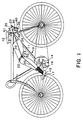
- the invention is shown associated with a conventional bicycle, in which 10 identifies a bicycle frame in which 11 is the main frame element on which a seat 12 is carried via a seat stem 13.
- the main axle 14 is carried at the lower end of the main frame 11.
- a pedal 15 is mounted at the free end of crank 16 which is connected at its other end to the main axle 14.
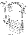
- the pedal 15 is rotatable about pedal axle 17, as is conventional, and the pedal axle 17 is longer than conventional, as shown in FIG. 3 where it provides inward and outwardly projecting axle extensions 18 and 19.
- the ligatures which connect the rider's thigh to the pedal powering system are rotatably mounted with respect to the axle extensions 18 and 19.
- the outer ligature on the near side of the bicycle can be seen in FIG. 1 where it is identified by numeral 20.
- the inner ligature 21 can be seen in FIG. 3.
- the two ligatures 20 and 21 relate to the same leg of the rider, and they are connected together by means of strap 22.
- the strap 22 rests upon the rider's thigh above the knee, as pictured, and it does not move with respect thereto.
- the end of the ligatures is connected to a fixed element 25 which is positioned beneath seat 12 and to the rear of the same. As seen in FIG. 1, the ligatures pull the strap 22 against the rider's thigh to maintain contact therebetween as the pedals are powered through their rotary cycle:
- the connecting element 25 is conveniently mounted on the rear forks 26, one of these forks being shown in FIGS. 1 and 2.
- the element 25 may be adjusted by turning horizontal rod 25, which may be accomplished by loosening screw 27.
- the ligatures, being secured to rod 25, maintain tension as the bicycle is operated.
- rod 25 is released by the interplay of elements 30, 35 and 36 and allowed to move forward, the tension on ligatures 20 and 21 is released, freeing the rider's legs to reach the ground.
- element 25 is simply a bar having holes 28 therein through which the rear end of the ligatures extend.
- the length of the ligature can be regulated by simply tying it on the far side of element 25, or if a more easily adjustable structure is desired, one can loosen Screw 27 and rotate bar 25 until the proper length of ligatures 20 and 21 is achieved.
- Element 25 extends laterally from a main support 30 which is pivotally mounted at 31 to a clamp 32 which is secured to the rear fork 26 by bolts 33 and 34.
- the main support 30 is prevented from moving forwardly by links 35 and 36.
- Link 36 is pivoted at 37 to clamp 32.
- link 35 is pivoted at one end to link 36 at 38 and at its other end to main support 30 at 39.
- link 30 In its locked position, link 30 is prevented from forward motion by links 35 and 36. In the locked position, link 35 is hinged with link 30, and forms a toggle structure in cooperation with link 36 to prevent link 30 from moving forward relative to the rider.
- Spring 40 ensures that the linkage returns to the locked position when tension on wire 41 is released.
- Wire 41 is connected to the brake system, usually by tying it to the brake wire running to the rear wheel, as shown in FIG. 1. In this way, whenever the brake is applied, wire 41 is pulled forwardly to move pivot 38 forwardly which allows main support 30 to move forwardly to allow element 25 to move forwardly, thereby easing the tension on the ligatures.
- Brake power is used only to unlock the system.
- the further forward motion of element 25 is accomplished by motion of the rider's leg; such sidewise or forward motion of the leg carries Strap 22 and attached ligatures 20 and 21 to pull element 25 forward into the fully unlocked position.
- spring 40 acts to bring the system back to its locked position.
- FIG. 3 the inner and outer extensions 18 and 19 of the pedal axle 17 are easily seen as is the rotatable mounting of the ligatures 20 and 21 on these extensions. Also visible are the pulleys 23 and 24 on which the ligatures ride. These pulleys are connected to the ends of strap 22 by means of links 50 and 51.
- flaps 52 as shown in FIG. 1 to prevent skin and hair from becoming caught in the pulleys as the ligatures move longitudinally therethrough.
- strap 22 in two sections 53 and 54 which are interconnected in releasable fashion at 55.
- releasable interconnection acts as a safety mechanism by allowing the rider to extricate himself from the device quickly.
- the release mechanism may be structured like seat belts in aircraft, or in any desired fashion.
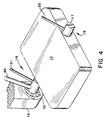
- FIG. 4 a pedal crank assembly is shown.
- a bearing 70 is mounted near the terminal of crank 16. This pedal-crank-bearing structure allows the pedal to rotate while providing effective attachment points 18 and 19 for ligatures 20 and 21.
- the structure in one implementation in a stationary device, can include a hand-operated element 60 which is connected at its lower end to the pedal axle 17. This hand element is preferred when the structure is used for exercise purposes rather than on a wheeled vehicle, like a bicycle.
- the strap which rests above the knee can be made of leather, plastic or strong fabric, and the ligature can be made of nylon rope or metal wire.
Landscapes
- Engineering & Computer Science (AREA)
- Chemical & Material Sciences (AREA)
- Combustion & Propulsion (AREA)
- Transportation (AREA)
- Mechanical Engineering (AREA)
- Health & Medical Sciences (AREA)
- Orthopedic Medicine & Surgery (AREA)
- Biophysics (AREA)
- Life Sciences & Earth Sciences (AREA)
- General Health & Medical Sciences (AREA)
- Physical Education & Sports Medicine (AREA)
- Motorcycle And Bicycle Frame (AREA)
- Orthopedics, Nursing, And Contraception (AREA)
- Mechanical Control Devices (AREA)
- Prostheses (AREA)
- Arrangement And Mounting Of Devices That Control Transmission Of Motive Force (AREA)
- Automatic Cycles, And Cycles In General (AREA)
- Steering Devices For Bicycles And Motorcycles (AREA)
- Control Of Throttle Valves Provided In The Intake System Or In The Exhaust System (AREA)
Claims (7)
- Eine pedalangetriebene Konstruktion, bestehend aus- einem Rahmen (10), der einen Sitz (12) trägt, und einer Hauptachse (14), die vorwärtig und unterhalb des Sitzes angeordnet ist,- einem Paar von Kurbelarmen (16), die jeweils einer auf jeder Seite mit der Achse (14) verbunden sind,- einem Pedal (15), das mittels einer Pedalachse (17) am freien Ende jedes Kurbelarms aufgehängt ist, das Pedal mit drehbarer Aufhängung an der Pedalachse, die Pedalachse, die über die Innenseite des Pedals hinaus verlängert ist, um so eine Verlängerung der Innenachse (18) zu bilden,- einem Zug (21), der an einem Ende mit der Verlängerung der Pedalachse (18) verbunden ist, während das andere Ende mit einem Element (25) verbunden ist, welches rückwärtig und unterhalb des Sitzes (18) angebracht ist,- einer Riemenanordnung (22), die an dem Zug (21) in der Mitte seiner Länge befestigt ist, so daß sie auf dem Schenkel des Fahrers oberhalb des Knies zu liegen kommt, wenn der Fahrer die pedalangetriebene Konstruktion benutzt,charakterisiert dadurch, daß- jede der Pedalachsen (17) über die Außenseite des Pedals (15) verlängert ist, um so eine äußere Verlängerung der Pedalachse (19) zu bilden,- ein zusätzlicher Zug (20) an einem Ende mit der äußeren Verlängerung jeder der Pedalachsen (19) verbunden ist, während das andere Ende mit einem Element (25) verbunden ist, welches rückwärtig und unterhalb des Sitzes (12) angebracht ist, um so zwei Paare paralleler Züge (20, 21) zu bilden, die ungefähr den Abstand der Breite des Pedals haben, und- die Riemenanordnung (22) zwischen jedem Paar der parallelen Züge (20, 21) befestigt ist.
- Die pedalangetriebene Konstruktion von Anspuch 1, bei der jeder Zug (20, 21) durch eine Seilrolle (23, 24) mit dem Ende eines Riemens verbunden ist, wobei eine Seilrolle an jedem Ende eines jeden Riemen (22) angebracht ist, so daß diese Anordnung es erlaubt, daß der Riemen (22) fest auf dem Schenkel oberhalb des Knies ruht, während sich die Züge (20, 21) in Bezug auf den Riemen der Länge nach bewegen, sobald der Fahrer die Pedale (15) antreibt.
- Die pedalangetriebene Konstruktion von Anspruch 2, bei der eine sich nach unten erstreckende Manschette (52) von jedem Ende eines jeden Riemens (22) gehalten wird, um Haare und Haut daran zu hindern, sich in der Seilrolle (23, 24) zu verfangen.
- Die pedalangetriebene Konstruktion von jedem der Ansprüche 1 bis 3, bei der jeder Riemen (22) aus zwei Teilen (53, 54), die lösbar miteinander verbunden sind, besteht.
- Die pedalangetriebene Konstruktion von jedem der Ansprüche 1 bis 4, die weiterhin Lager (70) beinhaltet, welche innerhalb der Kurbelarme (16) angebracht sind, und in welchen die Pedalachsen (17) drehbar in den Lagern aufgehängt sind.
- Die pedalangetriebene Konstruktion von jedem der Ansprüche 1 bis 5, bei der die von den Pedalachsen (17) entfernten Enden der Züge (20, 21) an einem starren Element (25) befestigt sind, welches lösbar ist, so daß sich das starre Element vorwärts verlagern kann, um somit die Spannung auf den Zügen zu lösen.
- Die pedalangetriebene Konstruktion von Anspruch 6, bei der das starre Element (25) durch Verbindungsglieder (35, 36), die einen Kniehebelverschluß darstellen, in einer rückwärtigen Position festgehalten wird, und Hilfsmittel (41) zur Befreiung des starren Elements (25) für die Vorwärtsverlagerung desselben Elements sind bereitgestellt.
Applications Claiming Priority (3)
| Application Number | Priority Date | Filing Date | Title |
|---|---|---|---|
| US297928 | 1989-01-17 | ||
| US07/297,928 US4909526A (en) | 1989-01-17 | 1989-01-17 | Thigh-assisted pedal powered structures |
| PCT/US1990/000271 WO1990007956A1 (en) | 1989-01-17 | 1990-01-11 | Thigh-assisted pedal-powered structures |
Publications (3)
| Publication Number | Publication Date |
|---|---|
| EP0454788A1 EP0454788A1 (de) | 1991-11-06 |
| EP0454788A4 EP0454788A4 (en) | 1992-05-06 |
| EP0454788B1 true EP0454788B1 (de) | 1995-09-13 |
Family
ID=23148301
Family Applications (1)
| Application Number | Title | Priority Date | Filing Date |
|---|---|---|---|
| EP90903265A Expired - Lifetime EP0454788B1 (de) | 1989-01-17 | 1990-01-11 | Mit pedalen angetriebene vom oberschenkel gesteuerte struktur |
Country Status (10)
| Country | Link |
|---|---|
| US (1) | US4909526A (de) |
| EP (1) | EP0454788B1 (de) |
| JP (1) | JPH04502742A (de) |
| KR (1) | KR910700086A (de) |
| AT (1) | ATE127699T1 (de) |
| AU (1) | AU661965B2 (de) |
| CA (1) | CA2045556C (de) |
| DE (1) | DE69022400T2 (de) |
| ES (1) | ES2038564A6 (de) |
| WO (1) | WO1990007956A1 (de) |
Families Citing this family (11)
| Publication number | Priority date | Publication date | Assignee | Title |
|---|---|---|---|---|
| US5848955A (en) * | 1992-05-26 | 1998-12-15 | University Of Utah Research Foundation | Muscle powered therapeutic vehicular system |
| US5501476A (en) * | 1992-05-26 | 1996-03-26 | University Of Utah Research Foundation | Muscle powered therapeutic vehicle |
| US5404771A (en) * | 1993-05-25 | 1995-04-11 | Soma; David N. | Device for disposing the toe clips on bicycle pedals in upright operative positions when the toe clips are not engaged by the cyclists shoes |
| GB2307888A (en) * | 1995-12-07 | 1997-06-11 | Russell John Searle | Bicycle with low centre of gravity |
| CA2253014A1 (fr) * | 1998-11-10 | 2000-05-10 | Andre Jacques | Preuves que la contraction du mollet ne peut pas augmenter la pression sur la pedale et mecanismes mettant a profit cette decouverte fondamentale |
| US6179760B1 (en) | 1999-02-09 | 2001-01-30 | Garry Rumbaugh | Method and device for assisting the leg muscles during cycling |
| CA2290097C (fr) * | 1999-10-25 | 2007-06-12 | Andre Jacques | Preuves que contraction du mollet ne peut pas augmenter la pression sur la pedale et mecanismes mettant a profit cette decouverte fondamentale |
| US6738987B1 (en) * | 2003-05-20 | 2004-05-25 | Douglas Harold Parks | Snap on, thigh to pedal, auxiliary propulsive system for bicycles |
| US9446278B2 (en) * | 2011-01-28 | 2016-09-20 | Sol Wroclawsky | Bicycle speed/resistance attachment |
| US8752851B2 (en) * | 2011-07-25 | 2014-06-17 | Shia-Lin Chen | Auxiliary device for bicycle |
| US10683054B2 (en) | 2017-09-26 | 2020-06-16 | Walter Edwin Croft | Bicycle frame attachable kneeling pad |
Citations (1)
| Publication number | Priority date | Publication date | Assignee | Title |
|---|---|---|---|---|
| DE107166C (de) * |
Family Cites Families (5)
| Publication number | Priority date | Publication date | Assignee | Title |
|---|---|---|---|---|
| DE63989C (de) * | l. M. kluge in Dresden, Dürerstrafse 92 | Eine durch die Oberschenkel des Fahrers zu betreibende Hilfsantriebvorrichtung für Fahrräder | ||
| BE398350A (de) * | ||||
| DE81199C (de) * | ||||
| FR896837A (fr) * | 1943-07-29 | 1945-03-05 | Dispositif permettant d'utiliser la cuisse pour exercer un effort de traction sur un pédalier | |
| CH670997A5 (de) * | 1986-09-23 | 1989-07-31 | Marco Geissmann |
-
1989
- 1989-01-17 US US07/297,928 patent/US4909526A/en not_active Expired - Lifetime
-
1990
- 1990-01-11 DE DE69022400T patent/DE69022400T2/de not_active Expired - Fee Related
- 1990-01-11 CA CA002045556A patent/CA2045556C/en not_active Expired - Fee Related
- 1990-01-11 WO PCT/US1990/000271 patent/WO1990007956A1/en not_active Ceased
- 1990-01-11 AT AT90903265T patent/ATE127699T1/de not_active IP Right Cessation
- 1990-01-11 JP JP2503399A patent/JPH04502742A/ja active Pending
- 1990-01-11 ES ES9050015A patent/ES2038564A6/es not_active Expired - Fee Related
- 1990-01-11 AU AU50815/90A patent/AU661965B2/en not_active Ceased
- 1990-01-11 EP EP90903265A patent/EP0454788B1/de not_active Expired - Lifetime
- 1990-09-17 KR KR1019900702064A patent/KR910700086A/ko not_active Abandoned
Patent Citations (1)
| Publication number | Priority date | Publication date | Assignee | Title |
|---|---|---|---|---|
| DE107166C (de) * |
Also Published As
| Publication number | Publication date |
|---|---|
| EP0454788A1 (de) | 1991-11-06 |
| AU661965B2 (en) | 1995-08-17 |
| CA2045556A1 (en) | 1990-07-18 |
| DE69022400T2 (de) | 1996-10-31 |
| US4909526A (en) | 1990-03-20 |
| WO1990007956A1 (en) | 1990-07-26 |
| AU5081590A (en) | 1990-08-13 |
| ATE127699T1 (de) | 1995-09-15 |
| KR910700086A (ko) | 1991-03-13 |
| CA2045556C (en) | 1999-03-30 |
| ES2038564A6 (es) | 1993-07-16 |
| JPH04502742A (ja) | 1992-05-21 |
| EP0454788A4 (en) | 1992-05-06 |
| DE69022400D1 (de) | 1995-10-19 |
Similar Documents
| Publication | Publication Date | Title |
|---|---|---|
| US4971316A (en) | Dual action exercise cycle | |
| US5000444A (en) | Dual action exercise cycle | |
| US5354083A (en) | Drive system for muscle-powered equipment and vehicles, in particular bicycles | |
| US3429584A (en) | Three-wheeled velocipede | |
| US6572128B2 (en) | Ratchet propulsion system for scooters | |
| EP0308587B1 (de) | Fahrrad-Trainingsgerät | |
| US5121654A (en) | Propulsion and transmission mechanism for bicycles, similar vehicles and exercise apparatus | |
| US5076600A (en) | Bicycle trailer | |
| EP0454788B1 (de) | Mit pedalen angetriebene vom oberschenkel gesteuerte struktur | |
| US6105985A (en) | Hand and foot powered bicycle | |
| US6557879B2 (en) | Land rower | |
| JPS5932355B2 (ja) | 自転車 | |
| US4470610A (en) | Children's safety pull toy | |
| US5269548A (en) | Exercise trailer | |
| CN108025795B (zh) | 骑行者驱动车辆及其机构 | |
| US5713590A (en) | Hand propelled velocipede, quadricycle | |
| DE19632519B4 (de) | Fahrrad mit Hand- und Fußkurbelantrieb und Bruststütze | |
| US5120074A (en) | Velocipede | |
| KR880002108B1 (ko) | 자전거 | |
| US20020113402A1 (en) | Human powered land vehicle combining use of legs and arms | |
| KR100311944B1 (ko) | 페달및새들운동에의해추진되는자전거 | |
| WO1990003304A1 (en) | A rider-propelled wheeled vehicle | |
| DE29515188U1 (de) | Liegedreirad mit Zusatzantrieb | |
| GB2309015A (en) | Folding bicycle | |
| US286180A (en) | cooper |
Legal Events
| Date | Code | Title | Description |
|---|---|---|---|
| PUAI | Public reference made under article 153(3) epc to a published international application that has entered the european phase |
Free format text: ORIGINAL CODE: 0009012 |
|
| AK | Designated contracting states |
Kind code of ref document: A1 Designated state(s): AT BE CH DE DK FR GB IT LI LU NL SE |
|
| 17P | Request for examination filed |
Effective date: 19910724 |
|
| A4 | Supplementary search report drawn up and despatched |
Effective date: 19920318 |
|
| AK | Designated contracting states |
Kind code of ref document: A4 Designated state(s): AT BE CH DE DK FR GB IT LI LU NL SE |
|
| 17Q | First examination report despatched |
Effective date: 19930611 |
|
| GRAA | (expected) grant |
Free format text: ORIGINAL CODE: 0009210 |
|
| AK | Designated contracting states |
Kind code of ref document: B1 Designated state(s): AT BE CH DE DK FR GB IT LI LU NL SE |
|
| PG25 | Lapsed in a contracting state [announced via postgrant information from national office to epo] |
Ref country code: DK Effective date: 19950913 Ref country code: AT Effective date: 19950913 |
|
| REF | Corresponds to: |
Ref document number: 127699 Country of ref document: AT Date of ref document: 19950915 Kind code of ref document: T |
|
| REF | Corresponds to: |
Ref document number: 69022400 Country of ref document: DE Date of ref document: 19951019 |
|
| ITF | It: translation for a ep patent filed | ||
| PG25 | Lapsed in a contracting state [announced via postgrant information from national office to epo] |
Ref country code: SE Effective date: 19951213 |
|
| PGFP | Annual fee paid to national office [announced via postgrant information from national office to epo] |
Ref country code: NL Payment date: 19960124 Year of fee payment: 7 |
|
| PG25 | Lapsed in a contracting state [announced via postgrant information from national office to epo] |
Ref country code: LU Free format text: LAPSE BECAUSE OF NON-PAYMENT OF DUE FEES Effective date: 19960131 Ref country code: LI Effective date: 19960131 Ref country code: CH Effective date: 19960131 |
|
| EN | Fr: translation not filed | ||
| PG25 | Lapsed in a contracting state [announced via postgrant information from national office to epo] |
Ref country code: FR Effective date: 19960209 |
|
| PGFP | Annual fee paid to national office [announced via postgrant information from national office to epo] |
Ref country code: BE Payment date: 19960305 Year of fee payment: 7 |
|
| EN | Fr: translation not filed |
Free format text: BO 96/06 PAGES 199 IL Y A LIEU DE SUPPRIMER:LA MENTION DE LA NON REMISE DE LA TRADUCTION |
|
| ET | Fr: translation filed | ||
| PLBE | No opposition filed within time limit |
Free format text: ORIGINAL CODE: 0009261 |
|
| STAA | Information on the status of an ep patent application or granted ep patent |
Free format text: STATUS: NO OPPOSITION FILED WITHIN TIME LIMIT |
|
| 26N | No opposition filed | ||
| REG | Reference to a national code |
Ref country code: CH Ref legal event code: PL |
|
| PGFP | Annual fee paid to national office [announced via postgrant information from national office to epo] |
Ref country code: FR Payment date: 19961221 Year of fee payment: 8 |
|
| PGFP | Annual fee paid to national office [announced via postgrant information from national office to epo] |
Ref country code: GB Payment date: 19970106 Year of fee payment: 8 |
|
| PG25 | Lapsed in a contracting state [announced via postgrant information from national office to epo] |
Ref country code: BE Effective date: 19970131 |
|
| PGFP | Annual fee paid to national office [announced via postgrant information from national office to epo] |
Ref country code: DE Payment date: 19970203 Year of fee payment: 8 |
|
| BERE | Be: lapsed |
Owner name: VAZIN HASSAN Effective date: 19970131 |
|
| PG25 | Lapsed in a contracting state [announced via postgrant information from national office to epo] |
Ref country code: NL Effective date: 19970801 |
|
| NLV4 | Nl: lapsed or anulled due to non-payment of the annual fee |
Effective date: 19970801 |
|
| PG25 | Lapsed in a contracting state [announced via postgrant information from national office to epo] |
Ref country code: GB Free format text: LAPSE BECAUSE OF NON-PAYMENT OF DUE FEES Effective date: 19980111 |
|
| GBPC | Gb: european patent ceased through non-payment of renewal fee |
Effective date: 19980111 |
|
| PG25 | Lapsed in a contracting state [announced via postgrant information from national office to epo] |
Ref country code: DE Free format text: LAPSE BECAUSE OF NON-PAYMENT OF DUE FEES Effective date: 19981001 |
|
| REG | Reference to a national code |
Ref country code: FR Ref legal event code: ST |
|
| PG25 | Lapsed in a contracting state [announced via postgrant information from national office to epo] |
Ref country code: IT Free format text: LAPSE BECAUSE OF NON-PAYMENT OF DUE FEES Effective date: 20050111 |