EP0454875B1 - Réglage à rétroaction du titre du mélange air-carburant dans les moteurs à combustion interne, en particulier dans les moteurs utilisant un carburant gazeux - Google Patents
Réglage à rétroaction du titre du mélange air-carburant dans les moteurs à combustion interne, en particulier dans les moteurs utilisant un carburant gazeux Download PDFInfo
- Publication number
- EP0454875B1 EP0454875B1 EP90108144A EP90108144A EP0454875B1 EP 0454875 B1 EP0454875 B1 EP 0454875B1 EP 90108144 A EP90108144 A EP 90108144A EP 90108144 A EP90108144 A EP 90108144A EP 0454875 B1 EP0454875 B1 EP 0454875B1
- Authority
- EP
- European Patent Office
- Prior art keywords
- circuit
- sensor
- signal
- actuator
- interface circuit
- Prior art date
- Legal status (The legal status is an assumption and is not a legal conclusion. Google has not performed a legal analysis and makes no representation as to the accuracy of the status listed.)
- Expired - Lifetime
Links
- 239000000446 fuel Substances 0.000 title claims description 39
- 238000002485 combustion reaction Methods 0.000 title claims description 14
- 230000033228 biological regulation Effects 0.000 claims description 20
- 239000000203 mixture Substances 0.000 claims description 20
- 239000007789 gas Substances 0.000 claims description 11
- QVGXLLKOCUKJST-UHFFFAOYSA-N atomic oxygen Chemical compound [O] QVGXLLKOCUKJST-UHFFFAOYSA-N 0.000 claims description 10
- 239000001301 oxygen Substances 0.000 claims description 10
- 229910052760 oxygen Inorganic materials 0.000 claims description 10
- 238000000034 method Methods 0.000 claims description 8
- 230000033001 locomotion Effects 0.000 claims description 7
- 230000001105 regulatory effect Effects 0.000 claims description 7
- 230000008569 process Effects 0.000 claims description 5
- 238000007789 sealing Methods 0.000 claims description 5
- 239000007788 liquid Substances 0.000 claims description 3
- 239000000567 combustion gas Substances 0.000 claims 2
- 238000001914 filtration Methods 0.000 claims 2
- 238000004458 analytical method Methods 0.000 claims 1
- 230000008033 biological extinction Effects 0.000 claims 1
- 230000007423 decrease Effects 0.000 claims 1
- 230000007613 environmental effect Effects 0.000 claims 1
- 230000002401 inhibitory effect Effects 0.000 claims 1
- 238000013519 translation Methods 0.000 description 10
- 230000014616 translation Effects 0.000 description 10
- 239000012528 membrane Substances 0.000 description 6
- 239000000523 sample Substances 0.000 description 6
- 230000009471 action Effects 0.000 description 3
- 230000008859 change Effects 0.000 description 3
- 230000006978 adaptation Effects 0.000 description 2
- 230000003750 conditioning effect Effects 0.000 description 2
- 238000010586 diagram Methods 0.000 description 2
- 238000009434 installation Methods 0.000 description 2
- 238000012545 processing Methods 0.000 description 2
- 238000012360 testing method Methods 0.000 description 2
- 238000010792 warming Methods 0.000 description 2
- 230000000903 blocking effect Effects 0.000 description 1
- 230000001276 controlling effect Effects 0.000 description 1
- 230000000694 effects Effects 0.000 description 1
- 239000004519 grease Substances 0.000 description 1
- 238000002347 injection Methods 0.000 description 1
- 239000007924 injection Substances 0.000 description 1
- 230000007257 malfunction Effects 0.000 description 1
- 238000012544 monitoring process Methods 0.000 description 1
- 239000000565 sealant Substances 0.000 description 1
- 230000007704 transition Effects 0.000 description 1
- 238000011144 upstream manufacturing Methods 0.000 description 1
Images


Classifications
-
- F—MECHANICAL ENGINEERING; LIGHTING; HEATING; WEAPONS; BLASTING
- F02—COMBUSTION ENGINES; HOT-GAS OR COMBUSTION-PRODUCT ENGINE PLANTS
- F02D—CONTROLLING COMBUSTION ENGINES
- F02D41/00—Electrical control of supply of combustible mixture or its constituents
- F02D41/0025—Controlling engines characterised by use of non-liquid fuels, pluralities of fuels, or non-fuel substances added to the combustible mixtures
- F02D41/0027—Controlling engines characterised by use of non-liquid fuels, pluralities of fuels, or non-fuel substances added to the combustible mixtures the fuel being gaseous
-
- F—MECHANICAL ENGINEERING; LIGHTING; HEATING; WEAPONS; BLASTING
- F02—COMBUSTION ENGINES; HOT-GAS OR COMBUSTION-PRODUCT ENGINE PLANTS
- F02D—CONTROLLING COMBUSTION ENGINES
- F02D19/00—Controlling engines characterised by their use of non-liquid fuels, pluralities of fuels, or non-fuel substances added to the combustible mixtures
- F02D19/02—Controlling engines characterised by their use of non-liquid fuels, pluralities of fuels, or non-fuel substances added to the combustible mixtures peculiar to engines working with gaseous fuels
- F02D19/021—Control of components of the fuel supply system
- F02D19/023—Control of components of the fuel supply system to adjust the fuel mass or volume flow
-
- F—MECHANICAL ENGINEERING; LIGHTING; HEATING; WEAPONS; BLASTING
- F02—COMBUSTION ENGINES; HOT-GAS OR COMBUSTION-PRODUCT ENGINE PLANTS
- F02M—SUPPLYING COMBUSTION ENGINES IN GENERAL WITH COMBUSTIBLE MIXTURES OR CONSTITUENTS THEREOF
- F02M21/00—Apparatus for supplying engines with non-liquid fuels, e.g. gaseous fuels stored in liquid form
- F02M21/02—Apparatus for supplying engines with non-liquid fuels, e.g. gaseous fuels stored in liquid form for gaseous fuels
- F02M21/0218—Details on the gaseous fuel supply system, e.g. tanks, valves, pipes, pumps, rails, injectors or mixers
- F02M21/023—Valves; Pressure or flow regulators in the fuel supply or return system
- F02M21/0233—Details of actuators therefor
-
- F—MECHANICAL ENGINEERING; LIGHTING; HEATING; WEAPONS; BLASTING
- F02—COMBUSTION ENGINES; HOT-GAS OR COMBUSTION-PRODUCT ENGINE PLANTS
- F02M—SUPPLYING COMBUSTION ENGINES IN GENERAL WITH COMBUSTIBLE MIXTURES OR CONSTITUENTS THEREOF
- F02M21/00—Apparatus for supplying engines with non-liquid fuels, e.g. gaseous fuels stored in liquid form
- F02M21/02—Apparatus for supplying engines with non-liquid fuels, e.g. gaseous fuels stored in liquid form for gaseous fuels
- F02M21/0218—Details on the gaseous fuel supply system, e.g. tanks, valves, pipes, pumps, rails, injectors or mixers
- F02M21/023—Valves; Pressure or flow regulators in the fuel supply or return system
- F02M21/0239—Pressure or flow regulators therefor
-
- F—MECHANICAL ENGINEERING; LIGHTING; HEATING; WEAPONS; BLASTING
- F02—COMBUSTION ENGINES; HOT-GAS OR COMBUSTION-PRODUCT ENGINE PLANTS
- F02M—SUPPLYING COMBUSTION ENGINES IN GENERAL WITH COMBUSTIBLE MIXTURES OR CONSTITUENTS THEREOF
- F02M21/00—Apparatus for supplying engines with non-liquid fuels, e.g. gaseous fuels stored in liquid form
- F02M21/02—Apparatus for supplying engines with non-liquid fuels, e.g. gaseous fuels stored in liquid form for gaseous fuels
- F02M21/06—Apparatus for de-liquefying, e.g. by heating
-
- Y—GENERAL TAGGING OF NEW TECHNOLOGICAL DEVELOPMENTS; GENERAL TAGGING OF CROSS-SECTIONAL TECHNOLOGIES SPANNING OVER SEVERAL SECTIONS OF THE IPC; TECHNICAL SUBJECTS COVERED BY FORMER USPC CROSS-REFERENCE ART COLLECTIONS [XRACs] AND DIGESTS
- Y02—TECHNOLOGIES OR APPLICATIONS FOR MITIGATION OR ADAPTATION AGAINST CLIMATE CHANGE
- Y02T—CLIMATE CHANGE MITIGATION TECHNOLOGIES RELATED TO TRANSPORTATION
- Y02T10/00—Road transport of goods or passengers
- Y02T10/10—Internal combustion engine [ICE] based vehicles
- Y02T10/30—Use of alternative fuels, e.g. biofuels
Definitions
- the present invention relates to a system for feeding an internal combustion engine with a gaseous fuel;
- the system comprises an evaporator pressure regulator, a connecting line arranged between the pressure regulator and a feed device of the mixture, a sensor of the oxygen concentration arranged in the outlet of the engine, an electronic control unit electrically connected to the sensor and an actuator electrically connected to the control unit; wherein the feed device has a throttle valve to control the flow of the mixture.
- the drive controls the flow of the fuel based on the signals from the sensor and revised by the control unit.
- Feed systems for internal combustion engines are known from the prior art, in which oxygen sensors arranged in the outlet are used to change the flow of the fuel as a function of the oxygen concentrations, the fuel being supplied by carburetors or injection valves.
- the known systems are based on the tasks, which essentially derive from the fact that a sensor should reach a predetermined operating temperature in order to output electrical signals which indicate the actual oxygen concentrations in the exhaust gases. If the temperature value of the sensor is below the value of the operating temperature, the signals coming from the sensor are not reliable; therefore the processing of these signals by electronic computers no meaning.
- a sensor reaches its operating temperature while the engine is warming up; the time interval required to reach this operating temperature depends on the ambient temperature and the stopping time of the motor.
- FR-A-2 577 993 relates to a continuous regulation method for supplying an internal combustion engine with gaseous fuel and a device for carrying out the method.
- the throttling element connected to a stepper motor moves between two end stops depending on the sigmoid signal of the ⁇ probe for regulating the flow of the fuel supplying the motor.
- a common computer with an internal timer, a speed sensor circuit and a temperature sensor is used to prevent the ⁇ regulation during the start up to a certain temperature.
- the control unit Since the temperature sensor is in the pressure regulator, he does not measure the temperature of the ⁇ probe, but a temperature that indicates the thermal state of the engine. The control unit therefore does not receive a signal that confirms or denies the sensor's operating status.
- the invention seeks to remedy this.
- the invention as characterized in the claims, solves the problem of creating a regulating system with back action of the titer of the air-fuel mixture for feeding an internal combustion engine, in particular an engine fed with gaseous fuel.
- the use of the invention results in the blocking of the control unit, so that the same control unit does not send any electrical signals to the drive while the engine is warming up, in order to prevent control of the drive on the basis of unreliable signals.
- the system according to the invention comprises the following elements: an evaporator pressure regulator connected to a container for a gaseous or liquid fuel; a conduit disposed between the pressure regulator and a body of a throttle valve for sending vaporized fuel from the pressure regulator to the body; an internal combustion engine equipped with an intake pipe to lead the air-fuel mixture into a combustion chamber of the engine; an outlet for the exhaust gases from the combustion chamber; an oxygen sensor ( ⁇ probe) provided within the outlet to analyze the oxygen concentration in the exhaust gases; an electronic control unit electrically connected to the sensor to receive an electrical signal from the sensor, a first and a second level of the signal indicating a lean and a rich ratio of the air-fuel mixture, the control unit being electrically driven connected, which is equipped with a movable member; wherein the drive consists of an electromechanical transducer; wherein the movable member runs between a first end stop and a second end stop and actuates a calibration element of the installation to control the flow of the fuel supplied to the body by the pressure regulator;
- the following devices are preferably provided in the system: Sealing means for preventing the entry of the gas from the line or from the regulator into the drive between the drive and the line, the sealing means ensuring the flow of the gaseous fuel from swirling movements which do not allow the flow of the gas through the line to be monitored; Lanyards that traverse the sealant to connect the drive to part of the system.
- the control unit essentially comprises the following circles: an adaptation and interface circuit of the sensor that decodes the levels of the electrical signal of the sensor; a control circuit of the drive, which is connected to the interface circuit in order to receive control signals from the interface circuit; the control signals cause the modulation circuit to control the drive so that the movable member actuates the calibration element in order to over-grease or deplete the mixture; a timing circuit connected to the interface circuit to receive a signal from the interface circuit get, which indicates the operational readiness of the sensor.
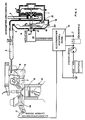
- the figures show a regulating system with back action of the titer of the air-fuel mixture for feeding an internal combustion engine, in particular an engine or individual parts of the system fed with gaseous fuel.
- the system according to the invention comprises a known evaporator pressure regulator 1, which has an inlet pipe 2 to connect the pressure regulator 1 to a container for a gaseous or liquid fuel, and a connecting pipe 3 for the outlet from the pressure regulator 1 of the vaporized fuel; on the connection pipe 3, a line 4 is fastened, which opens into a body 5 of a throttle valve upstream of a throttle valve 6;
- the air-fuel mixture is led through a suction line 7 into a combustion chamber 8 of the engine 9, in which it executes a working cycle.
- the exhaust gases exit from the combustion chamber 8 through an outlet 10.
- An oxygen sensor 11 (lambda probe) is screwed into the outlet 10 in order to analyze the oxygen concentration contained in the exhaust gases.
- the sensor 11 is electrically connected to an electronic control unit 12 in order to send an electrical signal to the control unit 12; in a known manner, a first and a second level of the signal each show a lean and a rich ratio of the air-fuel mixture.
- the control unit 12 is electrically connected to a drive 13 which has a slide 14; the drive 13 adjusts the slide 14 within a guide 15 from a first end stop A to a second end stop B and vice versa.
- the slide 14 is inserted in the line 4, therefore its movements proceed from the end stops A to the end stops B and vice versa in a direction which is perpendicular to the longitudinal axis of the line 4; if the slide 14 is in the end stops A, the area of the calibration cross section 16 of the gaseous fuel reaches its smallest value; If the slide 14 is in the end stops B, the area of the calibration cross section 16 reaches its greatest value.
- the slide 14 is suitable to be placed in any position, which is located between the end stops A and B, in order to change the area of the calibration cross section 16 in dependence on control signals which are sent by the control unit 12 are sent to the shoot 13; these control signals are processed on the basis of the first and the second level of the electrical signal coming from the sensor 11.
- the end stops A and B are adjustable to allow the correct regulation of the maximum and / or minimum flow of the fuel;
- known means are provided and not shown in FIGS. 1 and 2, which limit the respective end stops.
- An example of one of these means is shown in FIG. 5.
- the exemplary embodiment of the system shown in FIG. 2 differs from the exemplary embodiment shown in FIG. 1 only by a few components.
- the same reference numerals denote the same details; therefore we do not think it necessary to remember their name and arrangement in the system of Fig.2.
- the drive of the system shown in FIG. 2 has a rotor 17 which is driven by the drive 13 within the guide 15 in a first translation direction F 1 and in a second translation direction F 2, the translation directions F 1 and F 2 being perpendicular to the surface , which is limited by a membrane 18 of the second stage of the pressure regulator 1.
- a spring 19 is placed between the end of the rotor 17 and a plate 20 which solidifies the membrane 18; if the rotor 17 moves in the translation direction F 1, the membrane 18 increases its opening force for an outlet opening located between the first and the second stage of the pressure regulator 1 21; if the rotor 17 moves in the translation direction F2, the membrane 18 reduces its opening force for the outlet opening 21.
- the runner 17 is suitable to be placed in any position, which is between the outermost deflection in the translation direction F1 and the outermost deflection in the translation direction F2 to the force transmitted from the spring 19 to the membrane 18 depending on the to change control signals sent by the control unit 12 to the drive 13, which are processed on the basis of the first or the second level of the electrical signal coming from the sensor 11.
- end positions caused by the translations in the directions F1 and F2 are changeable to allow the correct regulation of the maximum and / or the minimum flow of the fuel;
- known means are provided and not shown in FIGS. 1 and 2, which limit the respective end stops.
- FIG. 3 shows a first exemplary embodiment of the drives 13; in this case the drive 13 consists of an electric motor 22 which is electrically connected to the control unit 12 in order to obtain control signals which determine the direction of rotation of a rotor 23.
- the rotor 23 is kinematically connected to a rod 24 by a known device which realizes the translations of the rod 24 in the directions of the arrows F3 and F4, while the rotor 23 rotates in the directions of the arrows F5 and F6, respectively.
- the rod 24 is kinematically connected to the slide 14 or to the rotor 17.
- FIG. 4 shows a second exemplary embodiment of the drive 13; in this case, the actuator 13 consists of a proportional solenoid valve 25 which is electrically connected to the control unit 12 in order to obtain control signals which determine the direction of translation of a movable armature 26 against the action of a spring 27.
- the armature 26 is kinematically connected to a rod 24 in order to drive the rod 24 in the directions of the arrows F7 and F9 depending on the current in the solenoid valve 25.
- the rod 24 is kinematically connected to the slide 14 or to the rotor 17.
- the item shown in Figure 5 relates to the line 4, which connects the pressure regulator 1 to the body 5; more precisely, the individual part relates to the calibration cross section 16 controlled by a slide 27.
- a rod 24 connects the slide 27 to a drive 13, which is similar to that shown in FIGS. 3 or 4.
- the slide 27 is partially supported within a guide bushing 28 which extends outside the line 4 and which has an axis of symmetry perpendicular to the line of symmetry of the line 4.
- the rod 24 passes through a hole provided in a plate 30; the plate 30 separates the line 4 from the interior 32 of a socket 33 carrying the drive 13 in order to protect the flow of the gaseous fuel from vortex movements which do not allow the flow of the gas through the line 4 to be monitored.
- a spring 31 clamps the plate 30 against an annular Surface 34, which is provided in the outer wall facing the interior 32.
- a regulating screw 29 is inserted in the interior of the guide bushing 28; the screw 29 has an axis of symmetry which coincides with the axis of symmetry of the socket 28.
- the tip of the screw 29 is suitable for stopping the movements of the slide 27 towards the inner space of the socket 28.
- the slide 27 reduces the area of the calibration cross section 16; If the drive 13 drives the slide 27 in the direction facing the interior of the bushing 28, the slide 27 increases the area of the calibration cross section 16.
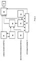
- FIG. 6 represents an electronic control unit 12 which can be used in any of the systems shown in FIGS. 1, 2 and 3.
- the following electrical circuits are essentially provided in the control unit 12:
- An adaptation and interface circuit 35 of the sensor 11 which is electrically connected to the sensor 11 in order to decode the levels of the respective electrical signal.
- the circuit 35 Based on the first level, the circuit 35 processes a first control signal for a control circuit 55 of the strut 13; on the basis of the second level, the circuit 35 processes a second control signal for the modulation circuit 55; for this purpose the circles 35 and 55 are electrical connected together.
- the first control signal causes the circuit 55 to control the drive 13 so that the rod 24 moves in the direction which enables the mixture supplied by the body 5 to be over-greased; the second control signal causes the circuit 55 to control the drive 13 so that the rod 24 moves in the direction which enables the mixture supplied by the body 5 to be depleted.
- An input and an output of the circuit 35 are electrically connected to a multiple timing circuit 40 so that the circuit 35 sends a signal to the circuit 40 indicating the operational readiness of the sensor 11.
- the operational readiness of the sensor 11 is determined by the district 40 at the end of a meaningless period. At the end of this time period, the transitions of the signal of the sensor 11 from the first to the second level clearly indicate that the sensor 11 is already in operation (namely that it has reached the operating temperature).
- the circuit 40 generates the periods of time that are necessary to allow the operation of the sensor 11.
- the circuit 40 stores the operational status of the sensor 11 and checks possible malfunctions or disassembly of the sensor 11 and / or the system by a test indicator, e.g. an LED connected to circuit 40.
- the circle 40 acts on the circle 35 during three successive periods T1, T2 and T3, which have expediently selected time period; the first period T1 begins when the ignition key closes.
- the circuit 40 sends a signal to the circuit 35 which makes it impossible for the circuit 35 to send the circuit 55 the first or the second control signal.
- the signal coming from the sensor 11 can have the first or the second level.
- the first level can indicate a lean titer of the mixture as well as a damage condition of the sensor 11 or the entire system (eg disassembly of the sensor 11, incorrect or damaged setting of the calibration devices of the system, etc.).
- the circuit 40 sends to the circuit 35 a signal which causes the circuit 35 to Circuit 55 to send the first or the second control signal, namely to control the drive 13.
- the circuit 40 sends to the circuit 35 a signal which permanently makes the circuit 35 incapable, to the circuit 55 the first or the second Send control signal.
- the circuit 40 sends to the circuit 35 at the end of the second period T2 a signal which causes the circuit 35 to the circuit 55 to send the first or the second control signal, namely to control the drive 13.
- the circuit 40 sends to the circuit 35 the signal which makes the circuit 35 unable to send to the circuit 55 the first or the second control signal; in addition, the circuit 40 activates the test vehicle to warn the driver of the damage to the system.
- switching the signal of the sensor 11 from the first to the second level, or vice versa allows the effect of the sensor 11 to be determined; in the case of switching, the circuit 40 causes the circuit 35 to send the first or the second control signal to the circuit 55, namely to control the drive 13 either at the end of the period T2 or in the course of the period T3.
- An output of the circuit 40 is connected to an input of a circuit 45 that generates reset and control clock signals.
- the circuit 45 is suitable for generating basic time signals during the reset phases when the ignition key is closed and during the control phase of the titer during regular operation of the engine.
- the circuit has 45 input circuits which stop the clock process when the sensor 11 is unusable or when the motor is in a damaged state (safety function).
- the control unit 12 comprises a reset and pre-regulation circuit 50 which ensures that the states of the drive 13 are zeroed when the ignition key is closed; the circuit therefore ensures 50 the pre-regulation of the titer by means of the drive 13 in the open-loop operating phases before the operational readiness of the 11 or in the event of damage to the same sensor.
- a first output of the circuit 50 is connected to an input of the circuit 45; a second output of the circuit 50 is connected to an input of the circuit 55.
- the control circuit 55 for the control of the drive 13 has inputs which are connected to the outputs of the circuits 35, 45 and 50. Means for controlling one of the drives used in the system are provided in the circuit 55.
- the control circuit 55 fulfills the task of decoding the signals of the direction and the speed of the movement of the drive 13 in order to ensure that the position of the drive 13 is reached, which is necessary for the correct monitoring of the titer of the mixture.
- a conditioning circuit 60 for conditioning a signal indicating the speed range of the engine is connected to the ignition coil.
- the processing circuit 60 processes the pulses occurring in the ignition coil and normalizes the signal coming from the ignition coil;
- the circuit 60 indicates a possible shutdown of the engine with the ignition key switched on in order to activate the safety circuits of the system.
- An output of the circuit 60 is connected to an input of the circuit 45.
- a pilot control circuit 65 is provided in the control unit 12, which pilot-controls the position of the drive 13 as a function of the temperature;
- the circuit 65 determines the various ambient temperature conditions of the system and the motor 9 and supplies various pre-regulation values for the drive 13 during the open-loop operating phase. Therefore, the circuit 65 is electrically connected to a temperature sensor and has an output connected to the circuit 55.
- the drive 13 consists of an electromechanical transducer, the purpose of which is to regulate the area of the calibration cross section 16 and the opening force transmitted to the membrane 18 as a function of the switching information from the circuit 55 in order to control the flow of the pressure regulator 1 to the Control body 5 delivered fuel.
- the drive can win 13 different designs. Examples of these designs are: a proportional solenoid valve, a fast solenoid valve with a variable working circuit, a stepper motor, a DC motor, etc.
- a sieve and regulator circuit 75 feeds the circuits of the control unit 12 and supplies the power levels that match the drive used.
- the circuit 75 generates timing settings for the ignition and the extinguishing which are used for the operation of the internal timings.
- the circle 75 is also connected to the individual circles of the control unit 12.
Landscapes
- Engineering & Computer Science (AREA)
- Chemical & Material Sciences (AREA)
- Combustion & Propulsion (AREA)
- Mechanical Engineering (AREA)
- General Engineering & Computer Science (AREA)
- Chemical Kinetics & Catalysis (AREA)
- General Chemical & Material Sciences (AREA)
- Oil, Petroleum & Natural Gas (AREA)
- Analytical Chemistry (AREA)
- Output Control And Ontrol Of Special Type Engine (AREA)
Claims (8)
- Installation de réglage à rétroaction du titre du mélange air-carburant dans les moteurs à combustion interne, en particulier dans les moteurs utilisant un carburant gazeux comprenant les éléments suivants:
un réducteur-vaporisateur de pression (1) relié à un réservoir de combustible liquide ou gazeux;
une conduite (4) installée entre le réducteur (1) et une bride (5) équipée d'un papillon pour envoyer un combustible vaporisé par le réducteur (1) a la bride (5);
un moteur (9) équipé d'un conduit d'admission (7) pour amener le mélange air-combustible du conduit (5) à une chambre de combustion (8) du moteur (9);
un conduit d'échappement (10) pour les gaz combustibles qui sortent de la chambre de combustion (8);
un capteur d'oxygène (11) (Sonde Lambda) installé dans le conduit d'échappement (10) pour analyser la concentration en oxygène contenue dans les gaz de combustion;
une unité électronique de contrôle (12) reliée électriquement au capteur (11) pour recevoir un signal électrique du capteur (11), un premier et un second niveau du signal du capteur (11) représentant respectivement une composition pauvre et une composition riche du mélange, l'unité électronique de contrôle (12) étant reliée électriquement à un actionneur (13) pourvu d'un organe mobile (14,17,24,27); l'actionneur (13) étant constitué d'un transducteur électro-mécanique;
l'organe mobile (14,17,24,27) glissant entre une première (A,F) et une seconde (B,F) position de fin de course et agissant sur un élément de tarage (16,18) de l'installation pour contrôler le débit du carburant envoyé par le réducteur (1) à la bride du papillon (5);
caractérisée par le fait que sont prévus des moyens de réglage (29) qui délimitent la première (A,F) et/ou la seconde (B,F) position de fin de course afin d'obtenir un réglage du débit maximum et/ou du débit minimum du carburant;
l'unité de contrôle (12) étant équipée (12) de circuits (40,45,50) qui interrompent le réglage λ en cas d'erreur de la part du capteur (11) et/ou de l'installation. - Installation selon la Rev.1, caractérisée par le fait qu'elle comprend en plus des moyens d'étanchéité (14,17,24,30) empéchant le passage du gaz hors de la conduite (4) ou du réducteur (1) à l'actionneur (13), afin d'éviter la formation de turbulences qui entravent le contrôle de l'admittance du gaz dans la conduite (4); des éléments de raccordement traversant les moyens d'étanchéité (14,17,24,30) pour relier l'actionneur (13) à une partie (1,4) de l'installation.
- Installation selon la Rev.1, caractérisée par le fait que dans l'unité électronique de contrôle (12) sont prévus les circuits électriques suivants:
un circuit d'interface et de conditionnement (35) du capteur (11), qui décode les niveaux du signal électrique du capteur (11); sur la base du premier niveau le circuit d'interface (35) élabore un premier signal de commande pour un circuit de pilotage (55) de l'actionneur (13); sur la base du second niveau le circuit d'interface (35) élabore un second signal de commande pour le circuit de pilotage (55); le premier signal de commande autorise le circuit de pilotage (55) à piloter l'actionneur (13) de façon à ce que l'organe mobile (14,17,24,27) intervienne sur l'élément de tarage (16,18) pour enrichir le mélange; le second signal de commande autorise le circuit de pilotage (55) à piloter l'actionneur (13) de façon à ce que l'organe mobile (14,17,24,27) intervienne sur l'élément de tarage (16,18) pour apauvrir le mélange;
un circuit temporisateur multiple (40);
une entrée et une sortie de circuit d'interface (25) sont reliés électriquement avec un circuit temporisateur (40) de façon à ce que le circuit temporisateur (40) reçoive du circuit d'interface (35) un signal qui indique l'entrée en action du capteur (11);
le circuit tempotisateur (40) engendre les temporisations nécessaires pour permettre l'entrée en action du capteur (11), en plus le circuit temporisateur (40) mémorise l'état d'activité du capteur (11) et diagnostique les erreurs éventuelles du capteur (11) et/ou de l'installation; si le capteur (11) est en action, le circuit temporisateur (40) envoie au circuit d'interface (35) un signal qui autorise le circuit d'interface (35) à envoyer au circuit de pilotage (55) le premier ou le second signal de commande; en cas d'erreur de la part du cap teur (11) ou de l'installation, le circuit temporisateur (40) envoie au circuit d'interface (35) un signal qui empêche le circuit d'interface (35) d'envoyer au circuit de pilotage (55) le premier ou le second signal de commande; dans ce cas le circuit temporisateur (40) active un voyant;
un circuit d'horlogerie (45) qui engendre des signaux d'horlogerie de "reset" et "réglage"; le circuit d'horlogerie (45) engendre des signaux de base temps durant les phases de reset au moment de la fermeture de la clé de démarrage et durant la phase de réglage du titre dans le fonctionnement normal du moteur; en outre le circuit d'horlogerie (45) présente des entrées de blocage qui stoppent le processus d'horlogerie si le capteur (11) ou l'installation sont hors de marche;
un circuit de Reset et Pré-réglage (50) en liaison avec le circuit de pilotage (55) pourvoyant à la remise à zéro des conditions d'état de l'actionneur (13) à l'acte de la fermeture de la clé de démarrage et pour fixer à l'avance le réglage du titre au moyen de l'actionneur (13) dans les phases de fonctionnement sans rétroaction du moteur avant l'entrée en action du capteur (11) ou en cas d'avarie de ce capteur (11);
un circuit de conditionnement (60) relié à la bobine d'allumage pour le conditionnement d'un signal qui représente le régime de rotation du moteur (9); le circuit de conditionnement (60) reconnaît et normalise les impulsions manquantes dans la bobine; en outre le circuit de conditionnement (60) indique un éventuel arrêt du moteur (9), la clé insérée, pour activer les circuits de sécurité de l'installation;
un circuit de pré-réglage (65) qui règle préalablement la position de l'actionneur (13) en fonction de la température; le circuit de pré-réglage (65) est en liaison avec le circuit de Reset et Pré-réglage (50); le circuit de pré-réglage (65) identifie les différentes conditions d'environnement de l'installation et du moteur et fournit les différentes valeurs fixées à l'avance pour l'actionneur (13) durant les phases de fonctionnement sans rétroaction du moteur; le circuit de pré-réglage (65) est relié électriquement à un capteur de température;
un circuit de filtrage et de réglage (75) qui alimente les circuits de l'unité (12) et fournit les niveaux de puissance adaptés à l'actionneur utilisé; le circuit de filtrage et réglage (75) produit des contrôles temporels d'allumage et d'extinction qui sont utilisés pour le fonctionnement des temporisations internes. - Installation selon la Rev.3, caractérisée par le fait que le circuit temporisateur (49) intervient sur le circuit d'interface (35) en trois périodes de temps successifs (T₁,T₂,T₃) de durée choisie opportunément;
la période (T₁) commence au moment de la fermeture de la clé de démarrage; durant la période (T₁) le circuit temporisateur (40) envoie au circuit d'interface (35) le signal qui empêche le circuit d'interface (35) d'envoyer au circuit de pilotage (35) le premier et le second signal de commande;
lors de la période (T₂) et en cas de commutation manquante du signal du capteur (11) du premier au second niveau le circuit temporisateur (40) envoie au circuit d'interface (35) le signal qui empêche le circuit d'interface (35) d'envoyer au circuit de pilotage (55) le premier et le second signal de commande; durant la période (T₂) et en cas de commutation advenue du signal du capteur (11) du premier au second niveau ou de permanence du signal du capteur (11) dans le second niveau le circuit temporisateur (40) envoie au circuit interface (35) le signal qui autorise le circuit d'interface (35) à envoyer au circuit de pilotage (55) le premier et le second signal de commande;
en cas de permanence du signal du capteur (11) dans le premier niveau pour toute la période (T₃) le circuit temporisateur (40) envoie au circuit d'interface (35) le signal qui empêche le circuit d'interface (35) d'envoyer au circuit de pilotage (55) le premier et le second signal de commande et en outre active le voyant pour avertir le conducteur de l'avarie de l'installation;
si lors de la période (T₃) le signal du capteur (11) se maintient au second niveau et commute du premier au second niveau le circuit temporisateur (40) envoie au circuit d'interface (35) le signal qui autorise le circuit d'interface (35) à envoyer au circuit pilotage (55) le premier et le second signal de commande. - Installation selon les Rev. 1 et 2, caractérisée par le fait que l'organe mobile (14,17,24,27) est un obturateur (27) mécaniquement relié à l'actionneur (13) au moyen d'une tige (24) et l'élément de tarage est une section (16) transversale de la conduite (4); l'obturateur (27) est partiellement logé dans un manchon (28) qui s'étend au-delà de la conduite (4) et qui présente un axe de symétrie perpendiculaire à l'axe de symétrie de la conduite (4); un plateau (30) divisant le conduit (4) d'une partie interne (32) d'un manchon (33) qui soutient l'actionneur (13); le plateau (30) présentant une perforation traversée par la tige (24).
- Installation selon la Rev. 5, caractérisée par le fait qu'une vis de réglage (29) est introduite dans la partie intérieure du manchon (28);
la vis (29) présentant un axe de symétrie qui coïncide avec l'axe de symétrie du manchon (33);
la pointe de la vis (29) arrêtant les mouvements de l'obturateur (27) dans le sens tourné vers la partie intérieure du manchon (28). - Installation selon les Rev. 1 et 2, caractérisé par le fait que l'organe mobile (14,17,24,27) est un obturateur (14) mécaniquement relié à l'actionneur (13) par une tige (24) et l'élément de tarage est une section transversale (16) de la conduite (4); l'actionneur (13) dispose l'obturateur (14) dans une position comprise entre une première position réglable (A) et une seconde position réglable (B) pour varier l'aire de la section de tarage (16) en fonction des signaux de commande envoyés par l'unité (12) à l'actionneur (13); les signaux de commande étant élaborés sur la base du premier et du second niveau du signal électrique qui provient du capteur (11).
- Installation selon les Rev.1 et 2, caractérisée par le fait que l'organe mobile (14,17,24,27) est un curseur (17) mécaniquement relié à l'actionneur (13) par une tige (24) et l'élément de tarage est le diaphragme (18) du second stade du réducteur (1); un ressort (19) est interposé entre l'extrémité du curseur (17) et un plateau (20) qui raidit le diaphragme (18); lorsque le curseur (17) passe dans un premier sens (F₁) le diaphragme (18) augmente sa force d'ouverture d'un orifice de passage (21) entre le premier et le second stade du réducteur (1) et quand le curseur (17) passe dans un second sens (F₂) le diaphragme (18) diminue sa force d'ouverture de l'orifice (21), le curseur (17) étant apte à être disposé dans une position quelconque comprise entre l'excursion maximum dans le sens (F₁) et l'excursion maximum dans le sens (F₂), de façon à varier la force transmise par le ressort (19) au diaphragme (18) en fonction des signaux de commande envoyés à l'unité (12) de l'actionneur (13) qui sont élaborés sur la base du premier ou du second niveau du signal électrique qui provient du capteur (11).
Priority Applications (2)
| Application Number | Priority Date | Filing Date | Title |
|---|---|---|---|
| DE90108144T DE59004697D1 (de) | 1990-04-28 | 1990-04-28 | Regulierungsanlage mit Rückeinwirkung des Titers des Luft-Kraftstoffgemisches zur Speisung eines Verbrennungsmotors, insbesondere eines mit gasförmigem Brennstoff gespeisten Motors. |
| EP90108144A EP0454875B1 (fr) | 1990-04-28 | 1990-04-28 | Réglage à rétroaction du titre du mélange air-carburant dans les moteurs à combustion interne, en particulier dans les moteurs utilisant un carburant gazeux |
Applications Claiming Priority (1)
| Application Number | Priority Date | Filing Date | Title |
|---|---|---|---|
| EP90108144A EP0454875B1 (fr) | 1990-04-28 | 1990-04-28 | Réglage à rétroaction du titre du mélange air-carburant dans les moteurs à combustion interne, en particulier dans les moteurs utilisant un carburant gazeux |
Publications (2)
| Publication Number | Publication Date |
|---|---|
| EP0454875A1 EP0454875A1 (fr) | 1991-11-06 |
| EP0454875B1 true EP0454875B1 (fr) | 1994-02-23 |
Family
ID=8203936
Family Applications (1)
| Application Number | Title | Priority Date | Filing Date |
|---|---|---|---|
| EP90108144A Expired - Lifetime EP0454875B1 (fr) | 1990-04-28 | 1990-04-28 | Réglage à rétroaction du titre du mélange air-carburant dans les moteurs à combustion interne, en particulier dans les moteurs utilisant un carburant gazeux |
Country Status (2)
| Country | Link |
|---|---|
| EP (1) | EP0454875B1 (fr) |
| DE (1) | DE59004697D1 (fr) |
Families Citing this family (4)
| Publication number | Priority date | Publication date | Assignee | Title |
|---|---|---|---|---|
| ZA939334B (en) * | 1992-12-14 | 1994-10-03 | Transcom Gas Tecnologies Pty L | Engine control unit |
| US5390651A (en) * | 1993-10-29 | 1995-02-21 | Precision Engine Controls Corporation | Air/fuel ratio controller for larger internal combustion engines |
| IT1302629B1 (it) * | 1998-10-08 | 2000-09-29 | Landi Renzo Spa | Impianto di alimentazione, attuazione e controllo di un motore ascoppio alimentato ad iniezione di gas. |
| JP5841925B2 (ja) * | 2012-09-21 | 2016-01-13 | ヤンマー株式会社 | 内燃機関 |
Family Cites Families (3)
| Publication number | Priority date | Publication date | Assignee | Title |
|---|---|---|---|---|
| JPS5623549A (en) * | 1979-08-02 | 1981-03-05 | Fuji Heavy Ind Ltd | Air-fuel ratio controller |
| JPS5751935A (en) * | 1980-09-12 | 1982-03-27 | Nippon Denso Co Ltd | Air-to-fuel return controller |
| FR2577993B1 (fr) * | 1985-02-22 | 1989-06-16 | Totalgaz Cie Fse | Procede de regulation en continu de l'alimentation d'un moteur en carburant a l'etat gazeux et dispositif mettant en oeuvre ledit procede |
-
1990
- 1990-04-28 DE DE90108144T patent/DE59004697D1/de not_active Expired - Fee Related
- 1990-04-28 EP EP90108144A patent/EP0454875B1/fr not_active Expired - Lifetime
Also Published As
| Publication number | Publication date |
|---|---|
| EP0454875A1 (fr) | 1991-11-06 |
| DE59004697D1 (de) | 1994-03-31 |
Similar Documents
| Publication | Publication Date | Title |
|---|---|---|
| DE2245029C3 (de) | Verfahren und Vorrichtung zur Abgasentgiftung von Brennkraftmaschinen | |
| DE2553678C3 (de) | Regeleinrichtung für die Zusammensetzung eines einer Brennkraftmaschine zugeführten Luft/Brennstoff-Gemisches | |
| EP0039932B1 (fr) | Dispositif pour régler la proportion des gaz pour appareils anesthésiques | |
| EP2324291A2 (fr) | Système de sécurité dans une installation de combustion et procédé de fonctionnement de celle-ci | |
| EP0714478A1 (fr) | Dispositif de clapet de carburateur | |
| DE2847794C2 (de) | Kraftstoff-Einspritzanlage für die Brennkraftmaschine eines Kraftfahrzeuges | |
| EP0860597B1 (fr) | Méthode de test des connections de sondes lambda | |
| EP0624721B1 (fr) | Méthode d'identification de l'origine de pannes dans un système de régulation du mélange d'un moteur à combustion interne | |
| DE2604689A1 (de) | Elektronische steuereinrichtung zur zufuehrung eines optimalen kraftstoff-luftgemisches | |
| DE3230211C2 (fr) | ||
| EP2021602A1 (fr) | Dispositif modulaire d'alimentation en combustible d'une turbine à gaz | |
| DE3200096C2 (fr) | ||
| DE10303252B4 (de) | Steuerungsvorrichtung für eine Brennkraftmaschine mit einem variablen Ventiltrieb zur Veränderung der Öffnungs- und Schließcharakteristik des Einlassventils und/oder Auslassventils | |
| EP0454875B1 (fr) | Réglage à rétroaction du titre du mélange air-carburant dans les moteurs à combustion interne, en particulier dans les moteurs utilisant un carburant gazeux | |
| DE3739805C3 (de) | Vorrichtung zum Regeln der Drehzahl einer Brennkraftmaschine | |
| DE4113774C2 (fr) | ||
| DE3634163A1 (de) | Abgas-rezirkulationssystem fuer eine brennkraftmaschine | |
| DE4036844C2 (fr) | ||
| DE3011523C2 (de) | Luft-Brennstoff-Verhältnisregelanordnung für einen Verbrennungsmotor | |
| DE3409050C2 (fr) | ||
| EP0237624B1 (fr) | Organe de positionnement pour commander le débit d'un fluide | |
| CH688842A5 (de) | Einrichtung zur Ansteuerung des Motors des Gebläses eines Gebläsebrenners. | |
| DE19918851B4 (de) | Schrittmotor-Steuervorrichtung | |
| DE3029313A1 (de) | System zum regeln des luft-brennstoff-verhaeltnisses eines verbrennungsmotors | |
| DE3014842C2 (de) | Brennkraftmaschine |
Legal Events
| Date | Code | Title | Description |
|---|---|---|---|
| PUAI | Public reference made under article 153(3) epc to a published international application that has entered the european phase |
Free format text: ORIGINAL CODE: 0009012 |
|
| AK | Designated contracting states |
Kind code of ref document: A1 Designated state(s): AT BE CH DE DK ES FR GB GR IT LI LU NL SE |
|
| RBV | Designated contracting states (corrected) |
Designated state(s): BE DE FR IT NL |
|
| 17P | Request for examination filed |
Effective date: 19920424 |
|
| 17Q | First examination report despatched |
Effective date: 19920805 |
|
| RAP1 | Party data changed (applicant data changed or rights of an application transferred) |
Owner name: B.B. S.R.L. |
|
| GRAA | (expected) grant |
Free format text: ORIGINAL CODE: 0009210 |
|
| AK | Designated contracting states |
Kind code of ref document: B1 Designated state(s): BE DE FR IT NL |
|
| ITF | It: translation for a ep patent filed | ||
| REF | Corresponds to: |
Ref document number: 59004697 Country of ref document: DE Date of ref document: 19940331 |
|
| ET | Fr: translation filed | ||
| PLBE | No opposition filed within time limit |
Free format text: ORIGINAL CODE: 0009261 |
|
| STAA | Information on the status of an ep patent application or granted ep patent |
Free format text: STATUS: NO OPPOSITION FILED WITHIN TIME LIMIT |
|
| 26N | No opposition filed | ||
| NLS | Nl: assignments of ep-patents |
Owner name: LOTUS CARS LIMITED |
|
| REG | Reference to a national code |
Ref country code: FR Ref legal event code: TP |
|
| PGFP | Annual fee paid to national office [announced via postgrant information from national office to epo] |
Ref country code: BE Payment date: 19990421 Year of fee payment: 10 |
|
| PGFP | Annual fee paid to national office [announced via postgrant information from national office to epo] |
Ref country code: NL Payment date: 19990429 Year of fee payment: 10 Ref country code: FR Payment date: 19990429 Year of fee payment: 10 |
|
| PGFP | Annual fee paid to national office [announced via postgrant information from national office to epo] |
Ref country code: DE Payment date: 19990630 Year of fee payment: 10 |
|
| PG25 | Lapsed in a contracting state [announced via postgrant information from national office to epo] |
Ref country code: BE Free format text: LAPSE BECAUSE OF NON-PAYMENT OF DUE FEES Effective date: 20000430 |
|
| BERE | Be: lapsed |
Owner name: LOTUS CARS LTD Effective date: 20000430 |
|
| PG25 | Lapsed in a contracting state [announced via postgrant information from national office to epo] |
Ref country code: NL Free format text: LAPSE BECAUSE OF NON-PAYMENT OF DUE FEES Effective date: 20001101 |
|
| PG25 | Lapsed in a contracting state [announced via postgrant information from national office to epo] |
Ref country code: FR Free format text: LAPSE BECAUSE OF NON-PAYMENT OF DUE FEES Effective date: 20001229 |
|
| NLV4 | Nl: lapsed or anulled due to non-payment of the annual fee |
Effective date: 20001101 |
|
| PG25 | Lapsed in a contracting state [announced via postgrant information from national office to epo] |
Ref country code: DE Free format text: LAPSE BECAUSE OF NON-PAYMENT OF DUE FEES Effective date: 20010201 |
|
| REG | Reference to a national code |
Ref country code: FR Ref legal event code: ST |
|
| PG25 | Lapsed in a contracting state [announced via postgrant information from national office to epo] |
Ref country code: IT Free format text: LAPSE BECAUSE OF NON-PAYMENT OF DUE FEES;WARNING: LAPSES OF ITALIAN PATENTS WITH EFFECTIVE DATE BEFORE 2007 MAY HAVE OCCURRED AT ANY TIME BEFORE 2007. THE CORRECT EFFECTIVE DATE MAY BE DIFFERENT FROM THE ONE RECORDED. Effective date: 20050428 |