EP0454883A1 - Capteur capacitif - Google Patents
Capteur capacitif Download PDFInfo
- Publication number
- EP0454883A1 EP0454883A1 EP90108327A EP90108327A EP0454883A1 EP 0454883 A1 EP0454883 A1 EP 0454883A1 EP 90108327 A EP90108327 A EP 90108327A EP 90108327 A EP90108327 A EP 90108327A EP 0454883 A1 EP0454883 A1 EP 0454883A1
- Authority
- EP
- European Patent Office
- Prior art keywords
- electrode
- base body
- membrane
- capacitive sensor
- capacitance
- Prior art date
- Legal status (The legal status is an assumption and is not a legal conclusion. Google has not performed a legal analysis and makes no representation as to the accuracy of the status listed.)
- Granted
Links
- 239000003990 capacitor Substances 0.000 claims abstract description 15
- 230000001419 dependent effect Effects 0.000 claims abstract description 5
- 239000012528 membrane Substances 0.000 claims description 38
- XUIMIQQOPSSXEZ-UHFFFAOYSA-N Silicon Chemical compound [Si] XUIMIQQOPSSXEZ-UHFFFAOYSA-N 0.000 claims description 22
- 239000010703 silicon Substances 0.000 claims description 22
- 229910052710 silicon Inorganic materials 0.000 claims description 22
- 239000012212 insulator Substances 0.000 claims description 12
- 239000000463 material Substances 0.000 claims description 4
- 239000004065 semiconductor Substances 0.000 claims description 3
- 230000003071 parasitic effect Effects 0.000 abstract description 8
- 230000008859 change Effects 0.000 description 10
- KWYUFKZDYYNOTN-UHFFFAOYSA-M Potassium hydroxide Chemical compound [OH-].[K+] KWYUFKZDYYNOTN-UHFFFAOYSA-M 0.000 description 6
- 238000005530 etching Methods 0.000 description 6
- 239000011521 glass Substances 0.000 description 6
- 238000000034 method Methods 0.000 description 5
- 230000035945 sensitivity Effects 0.000 description 5
- 235000012431 wafers Nutrition 0.000 description 5
- VYPSYNLAJGMNEJ-UHFFFAOYSA-N Silicium dioxide Chemical compound O=[Si]=O VYPSYNLAJGMNEJ-UHFFFAOYSA-N 0.000 description 4
- 230000009467 reduction Effects 0.000 description 4
- 230000000694 effects Effects 0.000 description 3
- 230000008569 process Effects 0.000 description 3
- 230000008719 thickening Effects 0.000 description 3
- 229910052581 Si3N4 Inorganic materials 0.000 description 2
- 230000009471 action Effects 0.000 description 2
- YCIMNLLNPGFGHC-UHFFFAOYSA-N catechol Chemical compound OC1=CC=CC=C1O YCIMNLLNPGFGHC-UHFFFAOYSA-N 0.000 description 2
- 238000009413 insulation Methods 0.000 description 2
- 238000004519 manufacturing process Methods 0.000 description 2
- 239000000377 silicon dioxide Substances 0.000 description 2
- 235000012239 silicon dioxide Nutrition 0.000 description 2
- 239000000126 substance Substances 0.000 description 2
- 230000008646 thermal stress Effects 0.000 description 2
- PIICEJLVQHRZGT-UHFFFAOYSA-N Ethylenediamine Chemical compound NCCN PIICEJLVQHRZGT-UHFFFAOYSA-N 0.000 description 1
- 230000001133 acceleration Effects 0.000 description 1
- XAGFODPZIPBFFR-UHFFFAOYSA-N aluminium Chemical compound [Al] XAGFODPZIPBFFR-UHFFFAOYSA-N 0.000 description 1
- 229910052782 aluminium Inorganic materials 0.000 description 1
- 230000008901 benefit Effects 0.000 description 1
- 229910052681 coesite Inorganic materials 0.000 description 1
- 238000010276 construction Methods 0.000 description 1
- 229910052906 cristobalite Inorganic materials 0.000 description 1
- 238000005516 engineering process Methods 0.000 description 1
- 239000012530 fluid Substances 0.000 description 1
- 238000005259 measurement Methods 0.000 description 1
- 239000000203 mixture Substances 0.000 description 1
- 229910021421 monocrystalline silicon Inorganic materials 0.000 description 1
- 230000010355 oscillation Effects 0.000 description 1
- HQVNEWCFYHHQES-UHFFFAOYSA-N silicon nitride Chemical compound N12[Si]34N5[Si]62N3[Si]51N64 HQVNEWCFYHHQES-UHFFFAOYSA-N 0.000 description 1
- 229910052682 stishovite Inorganic materials 0.000 description 1
- 230000035882 stress Effects 0.000 description 1
- 239000000758 substrate Substances 0.000 description 1
- 229910052905 tridymite Inorganic materials 0.000 description 1
Images

Classifications
-
- G—PHYSICS
- G01—MEASURING; TESTING
- G01L—MEASURING FORCE, STRESS, TORQUE, WORK, MECHANICAL POWER, MECHANICAL EFFICIENCY, OR FLUID PRESSURE
- G01L9/00—Measuring steady of quasi-steady pressure of fluid or fluent solid material by electric or magnetic pressure-sensitive elements; Transmitting or indicating the displacement of mechanical pressure-sensitive elements, used to measure the steady or quasi-steady pressure of a fluid or fluent solid material, by electric or magnetic means
- G01L9/0041—Transmitting or indicating the displacement of flexible diaphragms
- G01L9/0072—Transmitting or indicating the displacement of flexible diaphragms using variations in capacitance
- G01L9/0073—Transmitting or indicating the displacement of flexible diaphragms using variations in capacitance using a semiconductive diaphragm
Definitions
- the invention relates to a capacitive sensor according to the preamble of the main claim.
- the capacitance of a measuring capacitor is changed by the action of a measured variable.
- This change in capacitance serves as a measure of the measured variable to be recorded.
- the change in capacitance can have different causes depending on the properties of this measured variable.
- this can be a change in the dielectric properties of the dielectric in the measuring capacitor caused by the action of a chemical substance.
- Capacitive sensors are particularly suitable for measuring mechanical quantities, for example force, pressure or acceleration, in which, under the effect of the quantity to be measured, a body provided with electrodes is mechanically deflected relative to another electrode and the associated change in capacitance is detected.
- capacitive sensors for measuring mechanical quantities have the advantage of lower temperature sensitivity. Capacitive sensors can also be produced with a higher sensitivity than piezoresistive sensors. Due to low mechanical For example, small deflections caused by forces are easier to detect directly as a change in path than the changes in a piezo resistance associated with these deflections due to the change in the voltage state.
- a pressure sensor which contains a rectangular silicon membrane which is part of an n-doped silicon carrier body and is located opposite a glass plate which lies in a vacuum-tight manner on a carrier frame surrounding the membrane.
- the surface of the glass plate opposite the silicon membrane is metallized and forms the counter electrode to the silicon membrane.
- the contacting of the metallized glass surface with the integrated circuit located on the silicon base body takes place in that a part of the carrier frame, which is also made of silicon, is p-doped and is connected to the metallized surface of the glass plate.
- the electrode spacing is about 2 ⁇ m and the volume between the two electrodes is evacuated.
- the change in capacity of this pressure sensor is about 14% at 4 x 10 be supplement Pa pressure difference.
- the integrated circuit is integrated in the support frame of the silicon membrane and essentially consists of a Schmitt trigger oscillator, the oscillation period of which depends on the capacitance of the pressure-sensitive capacitor.
- this known pressure sensor has disadvantages, particularly in the case of thermal stress. Due to the different thermal expansion coefficients of glass and silicon, mechanical stress occurs at the connection points, which undesirably influence the properties of the membrane.
- the integrated circuit for detecting the change in capacitance and the membrane are located on the same silicon body, so that the etching process steps and the IC manufacturing steps must take place on the same wafer.
- the invention is based on the object of specifying a capacitive sensor in which disturbing parasitic capacitances are largely reduced.
- the stated object is achieved according to the invention with the features of the main claim.
- the cantilevered arrangement of the electrode above the base body increases the distance between the electrode and the base body at least on part of the electrode surface. This increase in the distance results in a reduction in the parasitic capacitance occurring between this electrode and the base body.
- a capacitive sensor which contains a body which is designed as part of a membrane and which can be deflected mechanically relative to a base body.
- This body is preferably formed by a central thickening of the membrane, which is provided with a flat side facing away from the membrane and running parallel to it. This flat side can then be provided as an electrode of the capacitor formed with the body.
- Sensors which consist of a semiconductor material, in particular silicon, are particularly suitable for miniaturization, since they can be processed and structured particularly easily in a micromechanical manner. Structures in which the deflectable body and the base body consist of silicon are particularly advantageous.
- the electronic circuit for detecting the change in capacity can then be integrated both in the base body and in the deflectable body.
- hybrid chips are provided for the electronic circuit, for example are glued to the surface of the base body and are bonded or soldered to the electrodes of the base body.
- the etching steps required for producing the deflectable body and the self-supporting electrodes on the base body in micromechanical technology and for producing the integrated circuit can then be carried out on different silicon wafers.
- an arrangement is preferably provided in which the electrodes are arranged on or in an insulator layer which is supported on a plurality of bases.
- a capacitive sensor contains a body 6 which is provided with an electrode 16 and can be deflected relative to a fixed base body 8 a capacitive pressure sensor is shown, in which the body 6 is formed as part of a membrane 4 and is connected to a support frame 2 via this membrane 4.
- the body 6 is formed by a thickening in the central region of the membrane 4 and has a flat side facing the base body 8 and oriented parallel to the plane spanned by the membrane.
- the electrode 16 is arranged on this flat side.
- the thickening has the effect that when the membrane is deflected, the electrode 16 is essentially only displaced parallel to the direction of the deflection.
- the mechanical properties of the membrane 4 are not influenced by the electrode 16.
- the support frame 2, the membrane 4 and the body 6 are preferably made of monocrystalline silicon with a (100) surface.
- Membrane 4 and body 6 can then be produced by anisotropic etching, for example with a mixture of ethylenediamine and pyrocatechol EDP or potassium hydroxide KOH.
- the flanks between the membrane 4 and the body 6 and the support frame 2 are then formed by (111) surfaces, so that a membrane 4 results in the shape of a rectangular frame, over which in the center of the body 6 as a base in the form of a Truncated pyramid rises.
- an electrode 16 which is vapor-deposited on the body 6 and is made of aluminum Al, for example, is shown.
- the support frame 2, the membrane 4 and the body 6 can, however, also consist of highly doped silicon, so that an electrode which is specially vapor-deposited on the surface of the body 6 is not required.
- the support frame 2 is via an insulator layer 20, for example silicon dioxide SiO2 or silicon nitride Si3N4, vacuum-tight on a base body also made of silicon 8 applied.
- an insulator layer 20 for example silicon dioxide SiO2 or silicon nitride Si3N4, vacuum-tight on a base body also made of silicon 8 applied.
- the base body 8 is provided with a passage opening 14, through which a pressure P2 to be measured is transmitted to the membrane 4, for example by an incompressible fluid.
- an electrode 23, which forms a capacitor with the electrode 16, is arranged in the insulating layer 20 of the base body 8 opposite the electrode 16. Since the electrode 16 and the base body 8 are at the same potential, this capacitance to be measured is overlaid with a parasitic capacitance occurring between the electrode 23 and the base body 8, which leads to a reduction in sensitivity.
- the electrode 23 is therefore located in the insulator layer 20 in a region in which the insulator layer extends freely over the base body 8. Between this area and the base body 8 there is a trough 52 which can be produced by undercutting the insulator layer 20. This leads to an increase in the distance between the electrode 23 and the base body 8 and thus to a reduction in the capacitance of the parasitic capacitor formed from the electrode 23 and base body 8.
- a differential pressure sensor with a symmetrical structure in which the support frame 2, the membrane 4 and the body 6 are designed, for example, mirror-symmetrically to a plane of symmetry 9 running parallel to the plane of the membrane.
- the body 6 then has the shape of two truncated pyramids.
- the support frame 2 is arranged between the base body 8 and a cover plate 10, which is also provided with a passage opening 12 through which the membrane can be pressurized with a pressure P1.
- the space between cover plate 10 and membrane 4 is evacuated.
- a membrane 4 with a thickness of about 50 microns and a frame width of about 1 mm is provided in a pressure sensor for the measuring range 104 Pa.
- the base area of the truncated pyramid-shaped body 6 in this example is approximately 4 ⁇ 4 mm 2 and the distance between the electrode 16 and the electrodes 24 is approximately 5 to 10 ⁇ m.
- the body 6 and the cover plate 10 are also provided on their mutually facing flat sides with electrodes 18 and 25, which also form a capacitor.
- both the sensitivity can be increased and the cross-sensitivity can be reduced.
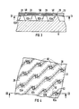
- Figure 2 shows the arrangement of the electrode 23 on the base plate 8 in a plan view.
- the electrode 23 is shown in dashed lines and is located in a web spanning the trough 52 made of insulator material, which has been produced by anisotropic undercutting.
- the side walls of the tub 52 are then formed in the case of a base body 8 with a (100) surface from (111) surfaces.
- electrodes 28 are therefore provided on the base body 8 in a particularly preferred embodiment of the invention, which electrodes are arranged on or in an only partially self-supporting insulator layer 20 above the base plate 8.
- the electrode 28 is supported on the truncated pyramid-shaped bases 82a, b, c, d via the insulator layer 20.
- FIG. 4 shows a sectional view of a surface section running parallel to the surface of the base plate 8 provided with the electrodes 28.
- the insulator layer 20 is supported on the base body 8 in a self-supporting manner via a plurality of bases and is provided with a plurality of slots 50, for example running in the [100] direction. These slots are required to undercut the insulation layer 20 and enable the anisotropic etchant to attack the silicon substrate of the base plate 8.
- the dimensions of the pyramid-shaped base 82 depend on the duration of exposure to the anisotropic etchant and become smaller as the etching process progresses. In a further embodiment of the invention, the etching process is continued to such an extent that these bases 82 also disappear and a self-supporting insulator layer 20 results, which is only connected to the base body 8 at its outer edges. Under this self-supporting insulator layer 20 is then similar to the embodiment according to FIGS. 1 and 2, a rectangular trough delimited by (111) side surfaces.
- the configurations according to the invention are not limited to embodiments with a single electrode arranged on the base body. Further electrodes which are electrically insulated from one another can also be located on the base body, so that a plurality of capacitors are formed with the deflectable body, the changes in capacitance of which are detected by measurement in a downstream electronic circuit.
Landscapes
- Physics & Mathematics (AREA)
- General Physics & Mathematics (AREA)
- Measuring Fluid Pressure (AREA)
- Pressure Sensors (AREA)
Priority Applications (2)
| Application Number | Priority Date | Filing Date | Title |
|---|---|---|---|
| EP90108327A EP0454883B1 (fr) | 1990-05-02 | 1990-05-02 | Capteur capacitif |
| DE59006845T DE59006845D1 (de) | 1990-05-02 | 1990-05-02 | Kapazitiver Sensor. |
Applications Claiming Priority (1)
| Application Number | Priority Date | Filing Date | Title |
|---|---|---|---|
| EP90108327A EP0454883B1 (fr) | 1990-05-02 | 1990-05-02 | Capteur capacitif |
Publications (2)
| Publication Number | Publication Date |
|---|---|
| EP0454883A1 true EP0454883A1 (fr) | 1991-11-06 |
| EP0454883B1 EP0454883B1 (fr) | 1994-08-17 |
Family
ID=8203945
Family Applications (1)
| Application Number | Title | Priority Date | Filing Date |
|---|---|---|---|
| EP90108327A Expired - Lifetime EP0454883B1 (fr) | 1990-05-02 | 1990-05-02 | Capteur capacitif |
Country Status (2)
| Country | Link |
|---|---|
| EP (1) | EP0454883B1 (fr) |
| DE (1) | DE59006845D1 (fr) |
Cited By (13)
| Publication number | Priority date | Publication date | Assignee | Title |
|---|---|---|---|---|
| DE4207952C1 (en) * | 1992-03-10 | 1993-04-15 | Mannesmann Ag, 4000 Duesseldorf, De | Capacitative differential pressure sensor for simple mfr. - comprises silicon diaphragm with edges having thinned areas, leaving central area, pressure input channels aligned with thickened edge region, and flat recesses |
| DE4333753A1 (de) * | 1993-10-04 | 1994-05-11 | Bosch Gmbh Robert | Kapazitiver Differenzdrucksensor |
| DE4106288C2 (de) * | 1991-02-28 | 2001-05-31 | Bosch Gmbh Robert | Sensor zur Messung von Drücken oder Beschleunigungen |
| US6362633B1 (en) | 1996-02-14 | 2002-03-26 | Stmicroelectronics S.R.L. | Capacitive distance sensor |
| US6437583B1 (en) | 1996-02-14 | 2002-08-20 | Stmicroelectronics, Inc.. | Capacitive distance sensor |
| US6472246B1 (en) | 1998-02-17 | 2002-10-29 | Stmicroelectronics, Inc. | Electrostatic discharge protection for integrated circuit sensor passivation |
| US6512381B2 (en) | 1999-12-30 | 2003-01-28 | Stmicroelectronics, Inc. | Enhanced fingerprint detection |
| US7923792B2 (en) | 2006-01-11 | 2011-04-12 | austruamicrosystems AG | MEMS sensor comprising a deformation-free back electrode |
| US8115497B2 (en) | 2007-11-13 | 2012-02-14 | Authentec, Inc. | Pixel sensing circuit with common mode cancellation |
| DE102015120074A1 (de) * | 2015-11-19 | 2017-05-24 | Endress+Hauser Gmbh+Co. Kg | Kapazitiver Differenzdrucksensor und Verfahren zu dessen Herstellung |
| CN109141728A (zh) * | 2018-07-18 | 2019-01-04 | 江苏大学 | 一种感压膜中间固定式电容压力传感器及制作方法 |
| CN116222830A (zh) * | 2021-12-06 | 2023-06-06 | 姜贵民 | 一种电容式芯片结构 |
| DE102010001797B4 (de) | 2010-02-11 | 2023-09-28 | Robert Bosch Gmbh | Mikromechanisches Sensorelement zur kapazitiven Differenzdruckerfassung |
Families Citing this family (4)
| Publication number | Priority date | Publication date | Assignee | Title |
|---|---|---|---|---|
| US6320394B1 (en) | 1996-02-14 | 2001-11-20 | Stmicroelectronics S.R.L. | Capacitive distance sensor |
| US6483931B2 (en) | 1997-09-11 | 2002-11-19 | Stmicroelectronics, Inc. | Electrostatic discharge protection of a capacitve type fingerprint sensing array |
| US6191593B1 (en) | 1997-12-17 | 2001-02-20 | Stmicroelectronics, Inc. | Method for the non-invasive sensing of physical matter on the detection surface of a capacitive sensor |
| US7239227B1 (en) | 1999-12-30 | 2007-07-03 | Upek, Inc. | Command interface using fingerprint sensor input system |
Citations (3)
| Publication number | Priority date | Publication date | Assignee | Title |
|---|---|---|---|---|
| FR1546836A (fr) * | 1966-11-07 | 1968-11-22 | United Aircraft Corp | Traducteur de pression |
| US3962921A (en) * | 1972-02-04 | 1976-06-15 | The Garrett Corporation | Compensated pressure transducer |
| EP0339981A2 (fr) * | 1988-04-29 | 1989-11-02 | Schlumberger Industries, Inc. | Capteur lamellé à semi-conducteur avec protection contre la surpression |
Family Cites Families (1)
| Publication number | Priority date | Publication date | Assignee | Title |
|---|---|---|---|---|
| US4785669A (en) * | 1987-05-18 | 1988-11-22 | Mks Instruments, Inc. | Absolute capacitance manometers |
-
1990
- 1990-05-02 DE DE59006845T patent/DE59006845D1/de not_active Expired - Fee Related
- 1990-05-02 EP EP90108327A patent/EP0454883B1/fr not_active Expired - Lifetime
Patent Citations (3)
| Publication number | Priority date | Publication date | Assignee | Title |
|---|---|---|---|---|
| FR1546836A (fr) * | 1966-11-07 | 1968-11-22 | United Aircraft Corp | Traducteur de pression |
| US3962921A (en) * | 1972-02-04 | 1976-06-15 | The Garrett Corporation | Compensated pressure transducer |
| EP0339981A2 (fr) * | 1988-04-29 | 1989-11-02 | Schlumberger Industries, Inc. | Capteur lamellé à semi-conducteur avec protection contre la surpression |
Cited By (15)
| Publication number | Priority date | Publication date | Assignee | Title |
|---|---|---|---|---|
| DE4106288C2 (de) * | 1991-02-28 | 2001-05-31 | Bosch Gmbh Robert | Sensor zur Messung von Drücken oder Beschleunigungen |
| DE4207952C1 (en) * | 1992-03-10 | 1993-04-15 | Mannesmann Ag, 4000 Duesseldorf, De | Capacitative differential pressure sensor for simple mfr. - comprises silicon diaphragm with edges having thinned areas, leaving central area, pressure input channels aligned with thickened edge region, and flat recesses |
| DE4333753A1 (de) * | 1993-10-04 | 1994-05-11 | Bosch Gmbh Robert | Kapazitiver Differenzdrucksensor |
| US6496021B2 (en) * | 1996-02-14 | 2002-12-17 | Stmicroelectronics, Inc. | Method for making a capacitive distance sensor |
| US6437583B1 (en) | 1996-02-14 | 2002-08-20 | Stmicroelectronics, Inc.. | Capacitive distance sensor |
| US6362633B1 (en) | 1996-02-14 | 2002-03-26 | Stmicroelectronics S.R.L. | Capacitive distance sensor |
| US6472246B1 (en) | 1998-02-17 | 2002-10-29 | Stmicroelectronics, Inc. | Electrostatic discharge protection for integrated circuit sensor passivation |
| US6610555B1 (en) | 1998-02-17 | 2003-08-26 | Stmicroelectronics, Inc. | Selectively doped electrostatic discharge layer for an integrated circuit sensor |
| US6512381B2 (en) | 1999-12-30 | 2003-01-28 | Stmicroelectronics, Inc. | Enhanced fingerprint detection |
| US7923792B2 (en) | 2006-01-11 | 2011-04-12 | austruamicrosystems AG | MEMS sensor comprising a deformation-free back electrode |
| US8115497B2 (en) | 2007-11-13 | 2012-02-14 | Authentec, Inc. | Pixel sensing circuit with common mode cancellation |
| DE102010001797B4 (de) | 2010-02-11 | 2023-09-28 | Robert Bosch Gmbh | Mikromechanisches Sensorelement zur kapazitiven Differenzdruckerfassung |
| DE102015120074A1 (de) * | 2015-11-19 | 2017-05-24 | Endress+Hauser Gmbh+Co. Kg | Kapazitiver Differenzdrucksensor und Verfahren zu dessen Herstellung |
| CN109141728A (zh) * | 2018-07-18 | 2019-01-04 | 江苏大学 | 一种感压膜中间固定式电容压力传感器及制作方法 |
| CN116222830A (zh) * | 2021-12-06 | 2023-06-06 | 姜贵民 | 一种电容式芯片结构 |
Also Published As
| Publication number | Publication date |
|---|---|
| EP0454883B1 (fr) | 1994-08-17 |
| DE59006845D1 (de) | 1994-09-22 |
Similar Documents
| Publication | Publication Date | Title |
|---|---|---|
| EP0454883B1 (fr) | Capteur capacitif | |
| EP0455070B1 (fr) | Capteur capacitif avec sortie de fréquence | |
| DE3741941C2 (fr) | ||
| DE4000903C1 (fr) | ||
| DE69529477T2 (de) | Verfahren zur herstellung eines kapazitiven absolutdrucksensors | |
| DE69925803T2 (de) | Mikromechanischer halbleiter-beschleunigungssensor | |
| DE68913177T2 (de) | Kapazitiver Drucksensor und Verfahren zum Minimieren der parasitären Kapazität eines kapazitiven Drucksensors. | |
| DE4106288C2 (de) | Sensor zur Messung von Drücken oder Beschleunigungen | |
| DE19810534C2 (de) | Mehrachsenbeschleunigungssensor und Herstellungsverfahren eines Mehrachsenbeschleunigungssensor | |
| DE19743749A1 (de) | Halbleiterdrucksensor | |
| EP0721587B1 (fr) | Dispositif micromecanique et son procede de fabrication | |
| DE69426451T2 (de) | Dielektrisch isolierter Mikroresonanzwandler | |
| DE69315544T2 (de) | Integrierter Beschleunigungsmesser mit zum Substrat paralleler Messachse | |
| DE3535904A1 (de) | Sensor fuer absolutdruck | |
| EP0981755B1 (fr) | Capteur d'acceleration | |
| DE19750131C2 (de) | Mikromechanische Differenzdrucksensorvorrichtung | |
| DE102012217979A1 (de) | Hybrid integriertes Drucksensor-Bauteil | |
| EP0494143B1 (fr) | Dispositif pour mesurer des forces mecaniques et des effets dynamiques | |
| WO1998023934A1 (fr) | Capteur micromecanique | |
| WO2008151972A2 (fr) | Capteur de pression différentielle | |
| DE4016471A1 (de) | Mikromechanischer neigungssensor | |
| WO1995008775A1 (fr) | Dispositif de detection micromecanique integre et son procede de production | |
| EP0710843B1 (fr) | Capteur d'accélération capacitif | |
| DE3837883A1 (de) | Kapazitiver beschleunigungsmesser und verfahren zu seiner herstellung | |
| DE69714204T2 (de) | Druckmessgerät |
Legal Events
| Date | Code | Title | Description |
|---|---|---|---|
| PUAI | Public reference made under article 153(3) epc to a published international application that has entered the european phase |
Free format text: ORIGINAL CODE: 0009012 |
|
| 17P | Request for examination filed |
Effective date: 19901205 |
|
| AK | Designated contracting states |
Kind code of ref document: A1 Designated state(s): DE FR GB IT |
|
| 17Q | First examination report despatched |
Effective date: 19930201 |
|
| GRAA | (expected) grant |
Free format text: ORIGINAL CODE: 0009210 |
|
| AK | Designated contracting states |
Kind code of ref document: B1 Designated state(s): DE FR GB IT |
|
| REF | Corresponds to: |
Ref document number: 59006845 Country of ref document: DE Date of ref document: 19940922 |
|
| ITF | It: translation for a ep patent filed | ||
| ET | Fr: translation filed | ||
| GBT | Gb: translation of ep patent filed (gb section 77(6)(a)/1977) |
Effective date: 19941121 |
|
| PLBE | No opposition filed within time limit |
Free format text: ORIGINAL CODE: 0009261 |
|
| STAA | Information on the status of an ep patent application or granted ep patent |
Free format text: STATUS: NO OPPOSITION FILED WITHIN TIME LIMIT |
|
| 26N | No opposition filed | ||
| PGFP | Annual fee paid to national office [announced via postgrant information from national office to epo] |
Ref country code: GB Payment date: 20010511 Year of fee payment: 12 |
|
| PGFP | Annual fee paid to national office [announced via postgrant information from national office to epo] |
Ref country code: FR Payment date: 20010522 Year of fee payment: 12 |
|
| PGFP | Annual fee paid to national office [announced via postgrant information from national office to epo] |
Ref country code: DE Payment date: 20010720 Year of fee payment: 12 |
|
| REG | Reference to a national code |
Ref country code: GB Ref legal event code: IF02 |
|
| PG25 | Lapsed in a contracting state [announced via postgrant information from national office to epo] |
Ref country code: GB Free format text: LAPSE BECAUSE OF NON-PAYMENT OF DUE FEES Effective date: 20020502 |
|
| PG25 | Lapsed in a contracting state [announced via postgrant information from national office to epo] |
Ref country code: DE Free format text: LAPSE BECAUSE OF NON-PAYMENT OF DUE FEES Effective date: 20021203 |
|
| GBPC | Gb: european patent ceased through non-payment of renewal fee |
Effective date: 20020502 |
|
| PG25 | Lapsed in a contracting state [announced via postgrant information from national office to epo] |
Ref country code: FR Free format text: LAPSE BECAUSE OF NON-PAYMENT OF DUE FEES Effective date: 20030131 |
|
| REG | Reference to a national code |
Ref country code: FR Ref legal event code: ST |
|
| PG25 | Lapsed in a contracting state [announced via postgrant information from national office to epo] |
Ref country code: IT Free format text: LAPSE BECAUSE OF NON-PAYMENT OF DUE FEES;WARNING: LAPSES OF ITALIAN PATENTS WITH EFFECTIVE DATE BEFORE 2007 MAY HAVE OCCURRED AT ANY TIME BEFORE 2007. THE CORRECT EFFECTIVE DATE MAY BE DIFFERENT FROM THE ONE RECORDED. Effective date: 20050502 |