EP0454905A1 - Procédé pour emmagasiner des fibres optiques raccordées par fusion dans un boîtier - Google Patents
Procédé pour emmagasiner des fibres optiques raccordées par fusion dans un boîtier Download PDFInfo
- Publication number
- EP0454905A1 EP0454905A1 EP90125742A EP90125742A EP0454905A1 EP 0454905 A1 EP0454905 A1 EP 0454905A1 EP 90125742 A EP90125742 A EP 90125742A EP 90125742 A EP90125742 A EP 90125742A EP 0454905 A1 EP0454905 A1 EP 0454905A1
- Authority
- EP
- European Patent Office
- Prior art keywords
- coil
- fusion
- spliced
- fiber
- casing
- Prior art date
- Legal status (The legal status is an assumption and is not a legal conclusion. Google has not performed a legal analysis and makes no representation as to the accuracy of the status listed.)
- Granted
Links
Images



Classifications
-
- G—PHYSICS
- G02—OPTICS
- G02B—OPTICAL ELEMENTS, SYSTEMS OR APPARATUS
- G02B6/00—Light guides; Structural details of arrangements comprising light guides and other optical elements, e.g. couplings
- G02B6/44—Mechanical structures for providing tensile strength and external protection for fibres, e.g. optical transmission cables
- G02B6/4439—Auxiliary devices
- G02B6/444—Systems or boxes with surplus lengths
- G02B6/4441—Boxes
Definitions
- the present invention relates to a method of preventing twisting of a fusion-spliced, tube-removed fiber portion in the process of encasing the fiber portion, in a coil form, in a casing.
- the protective tubes of the fiber cords are removed over a predetermined length, generally, 1 meter, from the ends of the fibers, which are to be fusion-spliced.
- the coating layers of the fibers are stripped off over a predetermined length from the ends of the fibers, which are fusion-spliced.
- the coating layer stripped fiber portions are disposed on a pair of supporting members of a fusion-splicing apparatus, with the fiber ends facing to one another. Thereafter, the fibers are moved to contact each other, while applied with arc discharge to the fiber ends, so that the fibers are fusion-spliced.
- the fusion-spliced portion does not have sufficient mechanical strength.
- the operator removes the fibers from the supporting members and cuts off the tip portions of the fibers by a predetermined length, generally, 35 mm, from the fusion-spliced portion.
- the fibers are again subjected to the above processes. This sequence is repeated until a good fusion-splicing is obtained.
- the length of the portion of each of the fibers where the protective tube is removed is generally set to about 1 meter. This portion of the fiber is referred to as "tube-removed fiber portion".
- the fusion-spliced fiber comprising the tube-removed fiber portions 161 and 162 is removed from the fusion-splicing apparatus, and put into a casing 14 to be held therein, as shown in Fig. 1A.
- the fusion-spliced portion 12 of the fusion-spliced fiber is fixed in a casing 14 as shown in Fig. 1A.
- the tube-removed fiber portions 161 and 162 of the fusion-spliced fiber are coiled as illustrated in Figs. 1A and 1B.
- a cover (not shown) of the casing 14 is closed to seal therein the fiber portion 161 and 162.
- the initial turn of coiling entails twisting with the upper fiber portion, for example, 161 at an intersection of the fiber portions 161 and 162, and further twisting emerge with every other turn of even numbers. It is likewise observed that the initial turn of coiling does not give rise to twisting with the lower fiber portion, for example, 162 but subsequent turns of the odd numbers after the third bring about twisting each.
- the tube-removed fiber portions 161 and 162 are each generally coiled in the form of a 3-turn.
- the twisting occurring is as intensive as not negligible with regard to optical characteristics, thereby inflicting the fibers some loss of optical transmission.
- the optical fiber interfere with deformation of the cable due to twisting, whereby resulting in causing ease for the coiled optical fiber to spring up, getting out of the casing, with safe workability to encase a coiled optical fiber and close a casing cover subsequently thus lessened.
- the present invention was devised to provide a method of preventing twisting the fusion-spliced, tube-removed fiber portions in the process of encasing the fiber portion, in a coilform, in a casing, whereby the fiber portions may be encased without undergoing twisting, springing up, and getting out of the casing, and workability of encasing the fiber portions may be improved.
- a method of preventing twisting of a fusion-spliced optical fiber in the process of encasing the optical fiber in a casing comprising the steps of: (a) winding one of a pair of optical fibers a predetermined number of turns in one direction to form a first coil, (b) restricting the first coil from expanding due to flexibility of the optical fiber, (c) winding another of the pair of optical fibers said predetermined number of turns in another direction opposite to the direction to form a second coil, (d) restrict-ing the second coil from expanding due to flexibility of the optical fiber, (e) fusion-splicing ends of remainder portions of the optical fibers which are not wound to each other, to form a fusion-spliced portion, (f) fixing the fusion-spliced portion within a casing, (g) releasing the restricting of the first and second coils from expanding, and, (h) pressing the remainder portions of the optical fibers into the casing to expand the first and second coil
- a method of preventing twisting of a fusion-spliced optical fiber in the process of encasing the optical fiber in a casing comprising the steps of: (a) winding one of a pair of optical fibers a predetermined number of turns in one direction to form a first coil, (b) restricting the first coil from expanding due to flexibility of the optical fiber, (c) winding another of the pair of optical fibers (N + 1) turns in another direction opposite to the direction to form a second coil, (d) restricting the second coil from expanding due to flexibility of the optical fiber, (e) fusion- splicing ends of remainder portions of the optical fibers which are not wound to each other, to form a fusion-spliced fiber with a fusion-spliced portion, (f) turning the fusion-spliced portion half a turn in the one direction to form the fusion-spliced fiber into a ring, (g) turning the ring of the fusion-
- a method of preventing twisting of a fusion-spliced optical fiber in the process of encasing the optical fiber in a casing comprising the steps of: (a) winding one of a pair of optical fibers N turns in one direction to form a first coil, (b) restricting the first coil from expanding due to flexibility of the optical fiber, (c) winding another of said pair of optical fibers (N+1) turns in another direction opposite to said one direction to form a second coil, (d) restricting the second coil from expanding due to flexibility of the optical fiber, (e) fusion-splicing ends of remainder portions of said optical fibers which are not wound to each other, to form a fusion-spliced fiber with a fusion-spliced portion, (f) turning said fusion spliced portion half a turn in said one direction to form said fusion-spliced fiber into a ring, (g) releasing said restricting of said second coil from expanding, (
- a casing commonly used at present can accommodate a coil whose diameter is 210 through 370 mm long.
- cutting-off of the fiber ends is not required to remove a defective fusion-spliced portion, and the length of each of the tube-removed fiber portions remains unchanged as being 1 m.
- the tube-removed fiber portions must suffer cutting to a length of 35 mm from each end of the fusion-spliced portion, resulting in shortening. Therefore, if the tube-removed fiber portions experience 10 successive attempts of fusion-splicing, with each resulting in producing a defective fusion-spliced portion, the total cut-off length would amount to 350 mm, and the resultant length of each tube-removed fiber portion would be 650 mm. With such tube-removed fiber portion, it is necessary to provide a three-turn coil with each turn measuring a length of 216 mm or a two-turn coil, with each turn measuring 325 mm.
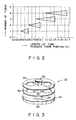
- the abscissa of the graph represents the total length of the tube-removed fiber portions while the ordinate denotes the number of turns.
- any one of the triangles may be selected to define the number of turns.
- the coil forming jig 22 comprises an ellipsoidal base 24, a cylindrical support 26 extending upward from the central part of the base 24, a lower winding core 28 inserted into the support 26, a center partition comprising elliptic disc 30, an upper winding core 32, an elliptic top disc 34, and a knob member 36 provided at the top of the support 26 to lock the above members through its thread engagement with the support 26.
- a fusion-spliced tube-removed fiber portion is wound around the coil forming jig 22, wherein around the lower winding core 28, one fiber portion is first wound N turns in one direction and then, a fiber holder (not shown) is pressure-inserted in between the center partition disc 30 and the ellipsoidal base 24 thereby to lock an optical fiber coil to the lower winding core 28.
- a fiber holder (not shown) is pressure-inserted in between the center partition disc 30 and the ellipsoidal base 24 thereby to lock an optical fiber coil to the lower winding core 28.
- another fiber portion is wound N turns in the direction opposite the above, followed by pressure-inserting a fiber holder (not shown) in between the center partition elliplic disc 30 and the elliptic top disc 34 whereby to another fiber coil to the upper winding core 32.
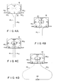
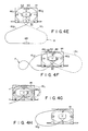
- a pair of optical fiber cables 421 and 422 are clamped by means of a pair of engaging clamp means 441 and 442 which are provided, respectively at the left and right corners on a side S1 of the rectangular casing 14.
- the tube-removed fiber portions 161 and 162 extend from the fiber cables 421 and 422 generally by 1 meter, respectively.
- ends of the tube-removed fiber portions 161 and 162 are fusion-spliced by a known conventional method.
- the process of fusion-splicing itself is not essential to the present invention, and thus the description thereof is omitted.
- the fusion-spliced, tube-removed fiber portion is given half a turn in the counterclockwise direction while holding the fusion-spliced portion 48. Namely, the fiber portion is turned 180°. This half a turn results in lapping the fiber portion 162 over the fiber portion 161, with the former thus intersecting the latter, whereby a ring R is formed.
- the ring R is turned upside down over the casing 14 so that the ring R will come to get situated on a S2 side opposite the S1 side of the casing 14 whereby the fusion-spliced portion 48 is pressure-inserted into a coil retaining clip 50 provided in proximity of the S2 side of the casing 14 to hold the fusion-spliced portion 48 therein.
- the turning of the ring R upside down produces a small twisted ring r either with the tube-removed fiber portion 161 or 162. Therefore, the operator involved is required to turn the ring R upside down as shown in Fig. 4F so that the small twisted ring r may come into existence with either of the tube-removed fiber portions, whichever is greater in the number of turns, namely with the fiber portion 162 with (N + 1) turns in this embodiment of the present invention.
- the fiber coil holder member 461 for the fiber portion 161 is removed to release the fiber coil which has thus far been thrust against the lower winding core 28. Under this condition, the fiber portion 161 lying outside the casing 14 is fed inside the casing so as to expand the size of the fiber coil.
- the coil holder member 462 provided for the tube-removed fiber portion 162 is removed thereby to release the fiber coil held thrust against the upper winding core 32, and one turn of the coil is taken off not only to make equal the number of turns with the N turns of the fiber coil 161 but also to make the small twisted ring r disappear.
- the tube-removed fiber portion 162 outside the casing 14 is fed into the casing thereby to enlarge the size of the coil.
- the coil forming jig 22 is removed from the casing 14, and a cover (not shown) is set in position.
- the tube-removed fiber portions 161 and 162 are wound around the lower and upper winding cores 28 and 32 without ring twisted since the ends of the tube-removed fiber portions are free when these fiber portions are wound around the winding cores, and a twist generated in a winding process undergoes offsetting in the subsequent winding process, thereby disappearing, whereby a twist-free ring is finally obtained.
- the step of taking off one turn of the fiber coil of the tube-removed fiber portion 162 is performed after the step of turning the ring R of the tube-removed fiber portion upside down is performed.
- these steps can be reversed. Specifically, after the step of turning the tube-removed fiber portion half a turn to form the ring R, the coil holder member 462 is removed to release the fiber coil of the tube-removed fiber portion 162 thrust against the upper winding core 32, and one turn of the fiber coil is taken off to make equal the number of turns with the N turns of the fiber coil of the tube-removed fiber portion 161.
- the ring R is turned upside down over the casing 14 so that the ring R will come to get situated on a S2 side opposite the S1 side of the casing 14 whereby the fusion-spliced portion 48 is pressure-inserted into a coil retaining clip 50.
- the fiber coil holder member 461 for the fiber portion 161 is removed to release the fiber coil thrust against the lower winding core 28.
- a pair of optical fiber cables 421 and 422 are fixed in their places.
- the tube-removed fiber portions 161 and 162 extend from the optical fiber cables 421 and 422 respectively. Thereafter, the tube-removed fiber portion 162 is wound N turns in the counterclockwise direction (in case the length of the tube-removed fiber portion is 1 meter, 3 turns) around the lower winding core 28 between the ellipsoidal base 24 and the center partition elliptic disc 30 of the coil forming jig removably mounted at the central part of the contain case 14.
- the optical fiber coil at the lower winding core 28 is thrust against the lower winding core 28 by pressure-inserting the coil holder member 462 in between the ellipsoidal base and the center partition elliptic disc.
- the remainder of the tube-removed fiber portion 162 is extended to the side S2 opposite the side S1 of the casing 14.
- the tube-removed fiber portion 161 is wound about the upper winding core 32 between the center partition elliptic disc 30 and the elliptic top disc 34 of the coil forming jig 22 the same number of turns as with the tube-removed fiber portion 162 in the clockwise direction. Then, the optical fiber coil at the upper winding core 32 is thrust against the upper winding core 32 by pressure inserting the coil holder member 461 in between the center partition elliptic disc and the elliptic top disc. The remainder of the tube-removed fiber portion 161 is extended to the side S2 of the casing 14.
- the ends of the tube-removed fiber portions 161 and 162 are fusion-spliced according to a known conventional method.
- the coating layers of the tip portions of the fiber portions 161 and 162 are removed, and the ends of the fiber portions are aligned in a line and fusion-spliced using arc discharge.
- the process of fusion-splicing is not within the scope of the present invention, and thus the detailed description thereof being omitted.
- the fusion-spliced portion 48 is pressure-inserted into the coil holding clip 50 for fixing thereto which is provided in proximity to the side S2 of the casing 14.
- the fiber coil holder member 462 for use with the optical fiber cable 162 is removed to release the optical fiber coil thus far held thrust against the lower winding core 28.
- the tube-removed fiber portion 162 staying outside the casing 14 is drawn into the casing to expand the size of the fiber coil.
- the coil holder member 461 for use with the tube-removed fiber portion 161 is removed thereby to release the optical fiber coil, which has so far been kept thrust against the upper winding core 32. Under this condition, the tube-removed fiber portions 161 lying outside the casing 14 is drawn into the casing thereby to increase the size of the optical fiber coil.
- Expanding the size of the optical fiber coils results in separating the tube-removed fiber portions sufficiently from the coil forming jig 22 whereby it becomes practicable at this stage to take out the coil forming jig 22 from the casing 14, followed by placing the cover (not shown) in position to close the casing.
- a wound-core type shown in Fig. 2 is employed for the coil forming jig
- a coil spring type shown in Fig. 6 may be applied to substitute for the wound core type.
- the coil spring type coil forming jig is characterized by its outstanding simple construction.
- a coil spring 52 with a tight winding structure is favorable so that a tube-removed fiber portion may be wound spirally while being caught between each neighboring two of the turns 54. After winding the fiber portion to a predetermined number of turns, the coil thus formed is fixed temporarily to the coil spring 52, using an engaging clamp members such as a clip, and so forth or an adhesive tape.
- an engaging clamp members such as a clip, and so forth or an adhesive tape.
- FIGs. 7A and 7B Shown in Figs. 7A and 7B is another example of the coil forming jig 22. These two figures give a plan view and a cross-sectional view of the another embodiment of the coil forming jig.
- the coil forming jig defined in this example is characterized in that the jig provides service with great ease of temporarily fixing the fiber coil to the jig as well as of releasing the fiber coil from the jig.
- this coil forming jig Structurally precise with this coil forming jig, it comprises a base 62, a cylindrical optical fiber winding core 64 integrally formed with the base 62 and which extends upward from the center part of the base 62, and optical fiber holding levers 701 and 702, pivottaly mounted to the base with respective pins 681 and 682.
- the lower ends of the pins 681 and 682 are set in left and right notches 661 and 662 provided in the base 62.
- a pair of flexible tongues 721 and 722 extend respectively left and right outward in the radial direction from the lower end of the optical fiber winding core 64.
- the tongues 721 and 722 hold the lower ends of the optical fiber holding levers 701 and 702, respectively, thereby to maintain these optical fiber holding levers at their vertical positions.
- the tongues 721 and 722 come into contact with the outside peripheries of the optical fiber holding levers 701 and 702, whereby these optical fiber holding levers 701 and 702 are maintained horizontally.
- the tube-removed fiber portion is wound a predetermined number of turns around the optical fiber winding core of the coil forming jig.
- the fiber portion wound into a coil is pressed against the optical fiber winding core 64 by means of the optical fiber holding levers 701 and 702, whereby the fiber coil is held around the winding core.
- one tube-removed fiber portion is wound in one direction around the lower part of the winding core, while the other tube-removed fiber portion is wound in the opposing direction around the upper part of the winding core.
- the ends of the tube-removed fiber portions wound into coils are fusion-spliced to each other by a known conventional method.
- the coil forming jig shown in each of Figs. 6, 7A and 7B it is allowed to wind either one tube-removed fiber portion 161 or 162 around one each coil forming jig.
- two tube-removed fiber portions 161 and 162 may be wound commonly around one coil forming jig.
- the method of the present invention eliminates the need of altering a conventional casing and allows repetitive use of the coil forming jig around which the tube-removed fiber portion is wound, whereby the running cost required for embodying the present invention may be maintained small without raising the production cost of the casing.
- both optical fibers 161 and 162 can be wound around the coil forming jig without being subjected to twisting, whereby ease is provided for expanding the size of a coilformed fiber portion within the casing.
Landscapes
- Physics & Mathematics (AREA)
- General Physics & Mathematics (AREA)
- Optics & Photonics (AREA)
- Mechanical Coupling Of Light Guides (AREA)
Applications Claiming Priority (4)
| Application Number | Priority Date | Filing Date | Title |
|---|---|---|---|
| JP88737/90 | 1990-04-03 | ||
| JP2088736A JP2608792B2 (ja) | 1990-04-03 | 1990-04-03 | 光ファイバ接続部の余長処理時の捻回防止方法 |
| JP88736/90 | 1990-04-03 | ||
| JP2088737A JP2608793B2 (ja) | 1990-04-03 | 1990-04-03 | 光ファイバ接続部の余長処理時の捻回防止方法 |
Publications (2)
| Publication Number | Publication Date |
|---|---|
| EP0454905A1 true EP0454905A1 (fr) | 1991-11-06 |
| EP0454905B1 EP0454905B1 (fr) | 1995-08-16 |
Family
ID=26430085
Family Applications (1)
| Application Number | Title | Priority Date | Filing Date |
|---|---|---|---|
| EP90125742A Expired - Lifetime EP0454905B1 (fr) | 1990-04-03 | 1990-12-28 | Procédé pour emmagasiner des fibres optiques raccordées par fusion dans un boîtier |
Country Status (3)
| Country | Link |
|---|---|
| US (1) | US5163988A (fr) |
| EP (1) | EP0454905B1 (fr) |
| DE (1) | DE69021715T2 (fr) |
Cited By (1)
| Publication number | Priority date | Publication date | Assignee | Title |
|---|---|---|---|---|
| WO2004013672A3 (fr) * | 2002-08-01 | 2009-04-02 | Fibercom B V | Dispositif de stockage de cable |
Families Citing this family (8)
| Publication number | Priority date | Publication date | Assignee | Title |
|---|---|---|---|---|
| US5546495A (en) * | 1993-04-16 | 1996-08-13 | The Whitaker Corporation | Splice tray rack and cabinet for fiber optic cables |
| US5492552A (en) * | 1994-03-03 | 1996-02-20 | Minnesota Mining And Manufacturing Company | Holder for annealing fiber optic coils |
| SE502553C2 (sv) * | 1994-03-15 | 1995-11-13 | Ericsson Telefon Ab L M | Optisk fiber för sensorändamål och sätt att framställa den optiska fibern |
| US5535298A (en) * | 1995-01-30 | 1996-07-09 | The Whitaker Corporation | Pedestal for fiber optic cable |
| US7428350B1 (en) * | 2007-07-18 | 2008-09-23 | Schlumberger Technology Corporation | Optical turnaround system |
| JP5673353B2 (ja) * | 2011-05-26 | 2015-02-18 | オムロン株式会社 | ファイバ保持具およびファイバレーザ装置 |
| US9606315B2 (en) | 2013-03-15 | 2017-03-28 | All Systems Broadband, Inc. | Optical fiber ribbon storage |
| US10437001B1 (en) * | 2018-09-20 | 2019-10-08 | The United States Of America As Represented By The Secretary Of The Navy | Fiber optic drogue and cable retraction spool |
Citations (4)
| Publication number | Priority date | Publication date | Assignee | Title |
|---|---|---|---|---|
| DE2914217A1 (de) * | 1979-04-09 | 1980-10-30 | Licentia Gmbh | Kassette zur aufnahme der vorratslaengen von lichtleitfasern |
| DE3405309A1 (de) * | 1984-02-15 | 1985-08-22 | Wilhelm Quante Spezialfabrik für Apparate der Fernmeldetechnik GmbH & Co, 5600 Wuppertal | Vorrichtung zur aufnahme der glasfaserspleisse von zu verbindenden glasfaser-kabeln |
| DE3413401A1 (de) * | 1984-04-10 | 1985-10-17 | Philips Patentverwaltung Gmbh, 2000 Hamburg | Aufnahme fuer die spleissverbindungen von lichtwellenleiterkabeln |
| EP0185923A1 (fr) * | 1984-11-20 | 1986-07-02 | MARS-ACTEL Société Anonyme dite: | Support de raccordement de fibres optiques |
Family Cites Families (11)
| Publication number | Priority date | Publication date | Assignee | Title |
|---|---|---|---|---|
| US3167895A (en) * | 1958-06-03 | 1965-02-02 | Kendall & Co | Method of filling suture package |
| IT1072041B (it) * | 1976-11-25 | 1985-04-10 | Cselt Centro Studi Lab Telecom | Sistema per l effettuazione di guinti in cavi ottici |
| US4274707A (en) * | 1979-06-14 | 1981-06-23 | Northern Telecom Limited | Apparatus for fusion splicing of optical fibers |
| US4359262A (en) * | 1980-06-30 | 1982-11-16 | Northern Telecom Limited | Tray for organizing optical fiber splices and enclosures embodying such trays |
| US4428645A (en) * | 1981-01-28 | 1984-01-31 | Gk Technologies, Incorporated | Cable accumulator |
| JPS5862605A (ja) * | 1981-10-09 | 1983-04-14 | Matsushita Electric Works Ltd | 光フアイバ端末装置 |
| DE3532312A1 (de) * | 1985-09-11 | 1987-03-12 | Philips Patentverwaltung | Verfahren zur herstellung einer verbindung zwischen zwei optischen leitungen und anordnung zur ausuebung des verfahrens |
| US4840449A (en) * | 1988-01-27 | 1989-06-20 | American Telephone And Telegraph Company, At&T Bell Laboratories | Optical fiber splice organizer |
| US4884863A (en) * | 1989-03-06 | 1989-12-05 | Siecor Corporation | Optical fiber splicing enclosure for installation in pedestals |
| US4932744A (en) * | 1988-10-04 | 1990-06-12 | Communications Technology Corporation | Closure for optical fiber splice connectors |
| GB8827348D0 (en) * | 1988-11-23 | 1988-12-29 | British Telecomm | Fibre distribution arrangement |
-
1990
- 1990-12-26 US US07/634,085 patent/US5163988A/en not_active Expired - Lifetime
- 1990-12-28 EP EP90125742A patent/EP0454905B1/fr not_active Expired - Lifetime
- 1990-12-28 DE DE69021715T patent/DE69021715T2/de not_active Expired - Fee Related
Patent Citations (4)
| Publication number | Priority date | Publication date | Assignee | Title |
|---|---|---|---|---|
| DE2914217A1 (de) * | 1979-04-09 | 1980-10-30 | Licentia Gmbh | Kassette zur aufnahme der vorratslaengen von lichtleitfasern |
| DE3405309A1 (de) * | 1984-02-15 | 1985-08-22 | Wilhelm Quante Spezialfabrik für Apparate der Fernmeldetechnik GmbH & Co, 5600 Wuppertal | Vorrichtung zur aufnahme der glasfaserspleisse von zu verbindenden glasfaser-kabeln |
| DE3413401A1 (de) * | 1984-04-10 | 1985-10-17 | Philips Patentverwaltung Gmbh, 2000 Hamburg | Aufnahme fuer die spleissverbindungen von lichtwellenleiterkabeln |
| EP0185923A1 (fr) * | 1984-11-20 | 1986-07-02 | MARS-ACTEL Société Anonyme dite: | Support de raccordement de fibres optiques |
Cited By (1)
| Publication number | Priority date | Publication date | Assignee | Title |
|---|---|---|---|---|
| WO2004013672A3 (fr) * | 2002-08-01 | 2009-04-02 | Fibercom B V | Dispositif de stockage de cable |
Also Published As
| Publication number | Publication date |
|---|---|
| DE69021715D1 (de) | 1995-09-21 |
| US5163988A (en) | 1992-11-17 |
| DE69021715T2 (de) | 1996-05-02 |
| EP0454905B1 (fr) | 1995-08-16 |
Similar Documents
| Publication | Publication Date | Title |
|---|---|---|
| US6278831B1 (en) | Fiber optic cable assembly | |
| US5997186A (en) | Hybrid cable splice closure and related methods | |
| US5163988A (en) | Method of preventing twisting of a fushion-spliced, tube-removed fiber portion in the process of encasing the fiber portion in a casing | |
| EP0159857A2 (fr) | Couverture d'épissage pour câble à fibres optiques | |
| WO1991012548A1 (fr) | Terminaison de cable | |
| JPH05142428A (ja) | スプライスのないフアイバ分岐を有する光フアイバケーブルおよびその製造方法 | |
| JPS6381407A (ja) | 光ファイバ−用保管装置 | |
| CA1299406C (fr) | Section de connexion de cable optique dans un cable composite de distribution electrique et de transmission optique | |
| US4889295A (en) | Optical fiber sleeving guide | |
| JP3033031B2 (ja) | 小形トランスの巻線方法 | |
| US6094518A (en) | Fiber optic cable restoration enclosure | |
| EP0450271A2 (fr) | Procédé de jonctionnement d'armure | |
| US20190004270A1 (en) | Cable management device and method | |
| JP3851739B2 (ja) | 超電導導体、超電導導体接続構造およびそれらを用いた超電導コイル | |
| JP2608793B2 (ja) | 光ファイバ接続部の余長処理時の捻回防止方法 | |
| WO1987004559A1 (fr) | Procede de fabrication d'enroulements toroidaux | |
| GB2138593A (en) | Handling Surplus Lengths of Optical Fibers at Cable Connection Points | |
| JPS58156915A (ja) | 光フアイバ−ケ−ブルの余長処理方法 | |
| JPH08262288A (ja) | 架空光ケーブル | |
| JPS58117513A (ja) | 光フアイバ接続余長部の収容方法 | |
| JPS5942511A (ja) | 光フアイバケ−ブル引通し部における外被接続部内へのフアイバ心線の収納方法 | |
| JPS5930898Y2 (ja) | 光ファイバケ−ブルの接続部 | |
| US6139193A (en) | Device for connecting two or more multiwire cables | |
| EP1153327B1 (fr) | Dispositif permettant de supprimer une torsion dans des rubans de fibres optiques | |
| JPH09312225A (ja) | 点火コイル |
Legal Events
| Date | Code | Title | Description |
|---|---|---|---|
| PUAI | Public reference made under article 153(3) epc to a published international application that has entered the european phase |
Free format text: ORIGINAL CODE: 0009012 |
|
| 17P | Request for examination filed |
Effective date: 19901228 |
|
| AK | Designated contracting states |
Kind code of ref document: A1 Designated state(s): DE GB SE |
|
| 17Q | First examination report despatched |
Effective date: 19930603 |
|
| GRAA | (expected) grant |
Free format text: ORIGINAL CODE: 0009210 |
|
| AK | Designated contracting states |
Kind code of ref document: B1 Designated state(s): DE GB SE |
|
| REF | Corresponds to: |
Ref document number: 69021715 Country of ref document: DE Date of ref document: 19950921 |
|
| PLBE | No opposition filed within time limit |
Free format text: ORIGINAL CODE: 0009261 |
|
| STAA | Information on the status of an ep patent application or granted ep patent |
Free format text: STATUS: NO OPPOSITION FILED WITHIN TIME LIMIT |
|
| 26N | No opposition filed | ||
| REG | Reference to a national code |
Ref country code: GB Ref legal event code: IF02 |
|
| PGFP | Annual fee paid to national office [announced via postgrant information from national office to epo] |
Ref country code: SE Payment date: 20051207 Year of fee payment: 16 |
|
| PGFP | Annual fee paid to national office [announced via postgrant information from national office to epo] |
Ref country code: GB Payment date: 20051228 Year of fee payment: 16 |
|
| PGFP | Annual fee paid to national office [announced via postgrant information from national office to epo] |
Ref country code: DE Payment date: 20060223 Year of fee payment: 16 |
|
| PG25 | Lapsed in a contracting state [announced via postgrant information from national office to epo] |
Ref country code: SE Free format text: LAPSE BECAUSE OF NON-PAYMENT OF DUE FEES Effective date: 20061229 |
|
| PG25 | Lapsed in a contracting state [announced via postgrant information from national office to epo] |
Ref country code: DE Free format text: LAPSE BECAUSE OF NON-PAYMENT OF DUE FEES Effective date: 20070703 |
|
| EUG | Se: european patent has lapsed | ||
| GBPC | Gb: european patent ceased through non-payment of renewal fee |
Effective date: 20061228 |
|
| PG25 | Lapsed in a contracting state [announced via postgrant information from national office to epo] |
Ref country code: GB Free format text: LAPSE BECAUSE OF NON-PAYMENT OF DUE FEES Effective date: 20061228 |