EP0454909B1 - Récepteur à fluide absorbeur pour générateur solaire spatial et système solaire spatial - Google Patents
Récepteur à fluide absorbeur pour générateur solaire spatial et système solaire spatial Download PDFInfo
- Publication number
- EP0454909B1 EP0454909B1 EP90250114A EP90250114A EP0454909B1 EP 0454909 B1 EP0454909 B1 EP 0454909B1 EP 90250114 A EP90250114 A EP 90250114A EP 90250114 A EP90250114 A EP 90250114A EP 0454909 B1 EP0454909 B1 EP 0454909B1
- Authority
- EP
- European Patent Office
- Prior art keywords
- working fluid
- receiving space
- heat
- cylindrical member
- wall
- Prior art date
- Legal status (The legal status is an assumption and is not a legal conclusion. Google has not performed a legal analysis and makes no representation as to the accuracy of the status listed.)
- Expired - Lifetime
Links
- 239000012530 fluid Substances 0.000 title claims abstract description 61
- 238000010248 power generation Methods 0.000 title 1
- 230000005855 radiation Effects 0.000 claims abstract description 17
- 239000006096 absorbing agent Substances 0.000 claims abstract description 7
- 230000008878 coupling Effects 0.000 claims abstract description 6
- 238000010168 coupling process Methods 0.000 claims abstract description 6
- 238000005859 coupling reaction Methods 0.000 claims abstract description 6
- 229910052736 halogen Inorganic materials 0.000 claims abstract description 5
- 150000002367 halogens Chemical class 0.000 claims abstract description 5
- 239000000463 material Substances 0.000 claims abstract 5
- 238000010438 heat treatment Methods 0.000 claims abstract 4
- 239000002918 waste heat Substances 0.000 claims description 9
- 150000003839 salts Chemical class 0.000 claims description 7
- 238000005338 heat storage Methods 0.000 claims description 5
- 238000000034 method Methods 0.000 claims description 5
- 239000011232 storage material Substances 0.000 claims description 5
- 230000005496 eutectics Effects 0.000 claims description 4
- 239000011261 inert gas Substances 0.000 claims description 4
- 230000008569 process Effects 0.000 claims description 4
- WKBOTKDWSSQWDR-UHFFFAOYSA-N Bromine atom Chemical compound [Br] WKBOTKDWSSQWDR-UHFFFAOYSA-N 0.000 claims description 3
- GDTBXPJZTBHREO-UHFFFAOYSA-N bromine Substances BrBr GDTBXPJZTBHREO-UHFFFAOYSA-N 0.000 claims description 3
- 229910052794 bromium Inorganic materials 0.000 claims description 3
- 229910052801 chlorine Inorganic materials 0.000 claims 2
- 239000000460 chlorine Substances 0.000 claims 2
- ZAMOUSCENKQFHK-UHFFFAOYSA-N Chlorine atom Chemical compound [Cl] ZAMOUSCENKQFHK-UHFFFAOYSA-N 0.000 claims 1
- 125000001309 chloro group Chemical group Cl* 0.000 claims 1
- 230000005611 electricity Effects 0.000 claims 1
- 230000001678 irradiating effect Effects 0.000 claims 1
- 238000004146 energy storage Methods 0.000 description 8
- 239000007789 gas Substances 0.000 description 4
- 238000010521 absorption reaction Methods 0.000 description 2
- 239000000470 constituent Substances 0.000 description 2
- 230000000694 effects Effects 0.000 description 2
- -1 bromine Chemical class 0.000 description 1
- 238000006243 chemical reaction Methods 0.000 description 1
- 238000005516 engineering process Methods 0.000 description 1
- 230000004927 fusion Effects 0.000 description 1
- 229910052734 helium Inorganic materials 0.000 description 1
- 239000001307 helium Substances 0.000 description 1
- SWQJXJOGLNCZEY-UHFFFAOYSA-N helium atom Chemical compound [He] SWQJXJOGLNCZEY-UHFFFAOYSA-N 0.000 description 1
- 230000007246 mechanism Effects 0.000 description 1
- 239000000203 mixture Substances 0.000 description 1
- 239000010453 quartz Substances 0.000 description 1
- 230000004044 response Effects 0.000 description 1
- 229910052594 sapphire Inorganic materials 0.000 description 1
- 239000010980 sapphire Substances 0.000 description 1
- VYPSYNLAJGMNEJ-UHFFFAOYSA-N silicon dioxide Inorganic materials O=[Si]=O VYPSYNLAJGMNEJ-UHFFFAOYSA-N 0.000 description 1
- 238000001228 spectrum Methods 0.000 description 1
- 229910052724 xenon Inorganic materials 0.000 description 1
- FHNFHKCVQCLJFQ-UHFFFAOYSA-N xenon atom Chemical compound [Xe] FHNFHKCVQCLJFQ-UHFFFAOYSA-N 0.000 description 1
Images
Classifications
-
- F—MECHANICAL ENGINEERING; LIGHTING; HEATING; WEAPONS; BLASTING
- F03—MACHINES OR ENGINES FOR LIQUIDS; WIND, SPRING, OR WEIGHT MOTORS; PRODUCING MECHANICAL POWER OR A REACTIVE PROPULSIVE THRUST, NOT OTHERWISE PROVIDED FOR
- F03G—SPRING, WEIGHT, INERTIA OR LIKE MOTORS; MECHANICAL-POWER PRODUCING DEVICES OR MECHANISMS, NOT OTHERWISE PROVIDED FOR OR USING ENERGY SOURCES NOT OTHERWISE PROVIDED FOR
- F03G6/00—Devices for producing mechanical power from solar energy
- F03G6/06—Devices for producing mechanical power from solar energy with solar energy concentrating means
- F03G6/064—Devices for producing mechanical power from solar energy with solar energy concentrating means having a gas turbine cycle, i.e. compressor and gas turbine combination
-
- F—MECHANICAL ENGINEERING; LIGHTING; HEATING; WEAPONS; BLASTING
- F03—MACHINES OR ENGINES FOR LIQUIDS; WIND, SPRING, OR WEIGHT MOTORS; PRODUCING MECHANICAL POWER OR A REACTIVE PROPULSIVE THRUST, NOT OTHERWISE PROVIDED FOR
- F03G—SPRING, WEIGHT, INERTIA OR LIKE MOTORS; MECHANICAL-POWER PRODUCING DEVICES OR MECHANISMS, NOT OTHERWISE PROVIDED FOR OR USING ENERGY SOURCES NOT OTHERWISE PROVIDED FOR
- F03G6/00—Devices for producing mechanical power from solar energy
- F03G6/071—Devices for producing mechanical power from solar energy with energy storage devices
-
- F—MECHANICAL ENGINEERING; LIGHTING; HEATING; WEAPONS; BLASTING
- F03—MACHINES OR ENGINES FOR LIQUIDS; WIND, SPRING, OR WEIGHT MOTORS; PRODUCING MECHANICAL POWER OR A REACTIVE PROPULSIVE THRUST, NOT OTHERWISE PROVIDED FOR
- F03G—SPRING, WEIGHT, INERTIA OR LIKE MOTORS; MECHANICAL-POWER PRODUCING DEVICES OR MECHANISMS, NOT OTHERWISE PROVIDED FOR OR USING ENERGY SOURCES NOT OTHERWISE PROVIDED FOR
- F03G6/00—Devices for producing mechanical power from solar energy
- F03G6/098—Components, parts or details
- F03G6/108—Components, parts or details of the heat transfer system
- F03G6/111—Heat transfer fluids
- F03G6/114—Molten salts
-
- F—MECHANICAL ENGINEERING; LIGHTING; HEATING; WEAPONS; BLASTING
- F24—HEATING; RANGES; VENTILATING
- F24S—SOLAR HEAT COLLECTORS; SOLAR HEAT SYSTEMS
- F24S20/00—Solar heat collectors specially adapted for particular uses or environments
- F24S20/20—Solar heat collectors for receiving concentrated solar energy, e.g. receivers for solar power plants
-
- F—MECHANICAL ENGINEERING; LIGHTING; HEATING; WEAPONS; BLASTING
- F24—HEATING; RANGES; VENTILATING
- F24S—SOLAR HEAT COLLECTORS; SOLAR HEAT SYSTEMS
- F24S70/00—Details of absorbing elements
- F24S70/10—Details of absorbing elements characterised by the absorbing material
-
- Y—GENERAL TAGGING OF NEW TECHNOLOGICAL DEVELOPMENTS; GENERAL TAGGING OF CROSS-SECTIONAL TECHNOLOGIES SPANNING OVER SEVERAL SECTIONS OF THE IPC; TECHNICAL SUBJECTS COVERED BY FORMER USPC CROSS-REFERENCE ART COLLECTIONS [XRACs] AND DIGESTS
- Y02—TECHNOLOGIES OR APPLICATIONS FOR MITIGATION OR ADAPTATION AGAINST CLIMATE CHANGE
- Y02E—REDUCTION OF GREENHOUSE GAS [GHG] EMISSIONS, RELATED TO ENERGY GENERATION, TRANSMISSION OR DISTRIBUTION
- Y02E10/00—Energy generation through renewable energy sources
- Y02E10/40—Solar thermal energy, e.g. solar towers
-
- Y—GENERAL TAGGING OF NEW TECHNOLOGICAL DEVELOPMENTS; GENERAL TAGGING OF CROSS-SECTIONAL TECHNOLOGIES SPANNING OVER SEVERAL SECTIONS OF THE IPC; TECHNICAL SUBJECTS COVERED BY FORMER USPC CROSS-REFERENCE ART COLLECTIONS [XRACs] AND DIGESTS
- Y02—TECHNOLOGIES OR APPLICATIONS FOR MITIGATION OR ADAPTATION AGAINST CLIMATE CHANGE
- Y02E—REDUCTION OF GREENHOUSE GAS [GHG] EMISSIONS, RELATED TO ENERGY GENERATION, TRANSMISSION OR DISTRIBUTION
- Y02E10/00—Energy generation through renewable energy sources
- Y02E10/40—Solar thermal energy, e.g. solar towers
- Y02E10/46—Conversion of thermal power into mechanical power, e.g. Rankine, Stirling or solar thermal engines
Definitions
- the present invention relates to a solar dynamic power system and a process for converting solar radiant power to electrical power. It relates specifically to a solar radiation receiver in which a large fraction of the radiation is absorbed directly by the working fluid of a heat engine. This creates new possibilities for increasing the fraction of the solar radiant power that is converted into electrical power. It also creates the possibility of simplifying the system architecture in ways that have numerous advantages.
- the receiver in the system discussed in the NASA study comprises one of various thermal eutectic salts, and the working fluid is an inert gas such as Helium/Xenon.
- the Systems proposed in the study have several practical disadvantages.
- the receiver of the study uses eutectic salts which make up the receiver cavity to directly absorb the concentrated solar radiation. This method of absorption limits the maximum operating temperature of the working fluid and thus also limits the efficiency of the heat engine which converts the absorbed energy to power. Moreover, because the walls of the receiving space absorb the concentrated solar energy, an increase in temperature of these systems would also cause an increase in radiant energy loss from the receiving space.
- US-A-4,069,673 discloses a turbine engine provided with a hermetically sealed housing and operative as a closed system in response to applied solar or other thermal energy. This prior art art system does not employ a latent heat storage material.
- Another object of the present invention is to provide a receiver for a solar dynamic power system which eliminates hot spots due to aiming errors in the concentrator of the power system.
- a still further object of the present invention is to provide a receiver with the smallest possible volume.
- Yet another object of the present invention is to provide a receiver which makes it possible to operate at a given turbine operating temperature, for example, with smaller temperature gradients in both the thermal energy storage portion and the receiver.
- An additional object of the present invention is to provide a complete solar dynamic power system of increased reliability which is easily protected from an external threat.
- the heat engine working fluid which circulates through the receiver cavity.
- the working fluid consists of a mixture of inert gases plus an absorber gas, which can be a halogen such as bromine, none of which radiate energy under these conditions.
- the insulating properties of the fluid and its flow rate through the cavity result in a much higher ratio of fluid operating temperature to cavity surface temperature than if the cavity surfaces were heated directly by absorbed radiation. This mitigates receiver radiation losses which limit the gains that can otherwise be achieved by the effect of higher fluid operating temperatures on the efficiency of heat engines.
- the receiver can be integrated with thermal energy storage, heat engine, recuperator, waste heat radiator, and alternator/generator modules to give a complete solar dynamic power system having significant advantages in compactness and weight/power ratio These advantages result both from the power efficiency associated with higher temperature operation and from the compact, cylindrically symmetrical geometry made possible by the rapid heat transport out of the receiver cavity.
- the simplicity of the overall system increases its inherent reliability and facilitates protection from external threat.
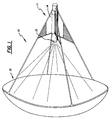
- Figure 1 shows an integrated solar dynamic power system 10 in which a collector 12, a large parabolic reflector, focuses solar radiation into receiver aperture inlet cone 13 at a first end of a cylindrical containment vessel 11. Except for heat sink means shown in the drawing as waste heat radiators 14, the modules associated with the receiver are integrated in cylindrical containment 11. The receiver containment vessel 11 and waste heat radiators 14 are oriented to minimize the shadow on the collector 12.
- the embodiment in figure 1 is suitable for either space or terrestrial applications. Alternatives for disposing of waste heat are possible.
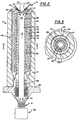
- FIG. 2 shows a lengthwise cross section of the modules in the cylindrical containment vessel 11.
- a hollow turbine axle 21 is rotatably disposed on the axis of the cylindrical containment 11.
- Axle 21 serves as a conduit for return gas flow to receiving space or cavity 22 and the inner wall 35 of the axle 21 absorbs a portion of the input radiation not absorbed by the working fluid.
- the working fluid follows a annular path up the turbine axle 21 toward entry window 24, and into flow space between the axle 21 and wall 20 of the containment vessel 11.
- Wall 20 may be insulated to minimize thermal energy loss.
- Quartz or sapphire entry window 24 which allows radiation to pass into the receiver cavity 22, has a conical shape with the apex of the cone directed into the receiver cavity 22, minimizing reflection losses and allowing the entire window surface to be swept by working fluid flowing through the receiver cavity 22.
- the edges 34 of the entry window 24 extend beyond the opening in the entry cone 13 to minimize the exposure of the window seal 25 to thermal and radiation stress.
- a significant part of the solar radiation that enters the receiver is absorbed by the halogen absorber constituent of the working fluid in a portion 33 of the receiver cavity 22 near the window 24.
- the absorber constituent is selected to absorb radiant energy in the widest possible spectrum while remaining opaque in the infra-red region.
- the unabsorbed radiation is transmitted to the wall 35 the turbine axle 21 where its energy is first absorbed by the wall 35, then transferred to the working fluid, preheating the fluid as it enters the receiver cavity 22.
- Absorption by the working fluid and rotation of the turbine axle 21 combine to prevent the effect of hot spots that might result from aiming errors. This allows the total receiver volume to be smaller than would otherwise be necessary.
- the working fluid After the working fluid is heated in the receiver cavity, it passes into flow space 23 between the axle 21 and the inner wall 20 of containment 11.
- the flow space 23 is divided into annular spaces 23, 26.
- the annular spaces 23, 26 are surrounded by sealed chambers 40, 41, 42 filled with fused salts which can store energy as latent heat of fusion.
- the geometry of the flow space is chosen to optimize surface area for heat transfer relative to the volume in which energy is stored and the volume through which the fluid flows.
- the chambers 40, 41, 42 together define a thermal energy storage module 43.
- the thermal energy storage module 43 is used to transfer heat between the working fluid and chambers 40, 41, 42 filled with partially molten salt, and has the same heat transfer rate at a given temperature difference.
- This configuration more than doubles the heat transfer efficiency of the same volume of heat storage material over that of designs using one wall of the thermal energy storage containment as the radiation receiver. This makes it possible to sustain a given turbine operating temperature with smaller temperature gradients in both the thermal energy storage module 43 and the receiving cavity 22.
- the operating temperature at which the working fluid leaves the lower portion of the energy storage module 43 and enters the heat engine is maintained at the temperature of the molten salt.
- heat is removed from thermal energy storage, starting at the top, where the fluid enters from the receiving cavity 22. The heat is replenished during the light cycle in which solar energy enters the receiving cavity 22.
- Figure 3 shows a cross section along the line 3-3 of Figure 2.
- the concentric relationship between receiving cavity 22 and annular spaces 23, 26 can easily be seen in Figure 3.
- the working fluid After passing through the annular spaces 23, 26 the working fluid enters the heat engine, shown in Figure 2 as a Brayton cycle engine which includes a gas turbine 27, recuperative heat exchanger 28 which transfers unusable heat to the working fluid returning to the receiving cavity 22, a waste heat exchanger 29 and a compressor 30, which together establish the necessary flow conditions.
- Waste heat exchanger 29 can be connected to waste heat radiators 14 shown in Figure 1, or any other suitable heat sink means.
- the thermal energy of the flowing gas is converted by turbine 27 to rotational energy of the turbine axle 21.
- the axle 21 is coupled by a magnetic coupling 31, or other mechanism which preserves the hermetically sealed containment, to a suitable generator or alternator 32 which converts the rotational energy to electrical power.
- the invention primarily concerns the receiver of a solar dynamic system.
- the preferred embodiment, described above, shows specifically how the receiver can be integrated with other necessary modules of a complete system in an overall architecture having advantages that accrue from the receiver concept.
Landscapes
- Engineering & Computer Science (AREA)
- Chemical & Material Sciences (AREA)
- Combustion & Propulsion (AREA)
- Sustainable Development (AREA)
- Sustainable Energy (AREA)
- Life Sciences & Earth Sciences (AREA)
- Mechanical Engineering (AREA)
- General Engineering & Computer Science (AREA)
- Thermal Sciences (AREA)
- Physics & Mathematics (AREA)
- Engine Equipment That Uses Special Cycles (AREA)
- Circuits Of Receivers In General (AREA)
- Optical Communication System (AREA)
- Charge And Discharge Circuits For Batteries Or The Like (AREA)
- Sorption Type Refrigeration Machines (AREA)
Claims (8)
- Générateur de puissance dynamique solaire ayant un moteur à cycle thermique pour générer de la puissance et un récepteur, comprenant :- un fluide moteur (22, 23, 23, 26) comprenant un absorbeur d'énergie rayonnée sélectionné parmi les halogènes et les interhalogènes ;- une cuve de confinement cylindrique creuse (11) pour contenir le fluide moteur ayant une première extrémité (13), une seconde extrémité (30) et une paroi (20) ;- un élément cylindrique creux (21) placé en étant rotatif à l'intérieur de la cuve de confinement (11) et ayant une paroi (35) définissant un espace de réception du fluide (22) ;- une fenêtre (24) placée dans la première extrémité de la cuve de confinement (11) pour admettre le rayonnement solaire dans l'espace de réception (22) pour chauffer le fluide moteur contenu dans l'espace de réception, le fluide moteur chauffé dans l'espace de réception (22) se déplaçant vers la première extrémité (13) de la cuve de confinement (11) ;- une matière pour emmagasiner la chaleur latente (40, 41, 42) placée dans l'espace d'écoulement entre la paroi (35) de l'élément cylindrique (21) et la paroi (20) de la cuve de confinement (11) définissant un espace toroïdal d'écoulement du fluide moteur (23, 26) à l'intérieur de la cuve de confinement pour emmagasiner la chaleur absorbée par le fluide moteur dans l'espace de réception (22) ;- une turbine (27) reliée à l'élément cylindrique (21) et placée en aval par rapport au fluide moteur de la matière qui emmagasine la chaleur latente, un écoulement de fluide moteur de la première (13) à la seconde (30) extrémité de l'espace d'écoulement provoquant la rotation de la turbine (27) et de l'élément cylindrique (21) ;- des moyens de dissipation de chaleur (29) placés en aval de la turbine (27) pour éliminer la chaleur perdue du fluide moteur ;- des moyens de compression (30) disposés en aval des moyens de dissipation de chaleur (29) pour comprimer le fluide moteur et introduire le fluide moteur comprimé dans l'espace de réception (22) ;- des moyens de génération (32) pour convertir la rotation de ladite turbine (27) et de l'élément cylindrique (21) en puissance électrique et- des moyens (31) pour coupler l'élément cylindrique (21) aux moyens de génération mentionnés (32).
- Appareil selon la revendication 1 dans lequel ladite matière qui emmagasine la chaleur latente (40, 41, 42) est un sel eutectique à chaleur latente.
- Appareil selon la revendication 1 dans lequel ledit absorbeur est sélectionné parmi le chlore, le brome et les interhalogènes de brome et de chlore.
- Appareil selon la revendication 3 dans lequel ledit fluide moteur comprend de plus un gaz inerte.
- Appareil selon la revendication 2 dans lequel la matière qui emmagasine la chaleur latente comprend une pluralité de cylindres substantiellement concentriques disposés entre ledit élément cylindrique (21) et la paroi intérieure de ladite cuve de confinement (11).
- Appareil selon la revendication 5 dans lequel les cylindres concentriques mentionnées comprennent des chambres hermétiques remplies de sels eutectiques à chaleur latente.
- Procédé de génération de puissance dynamique solaire ayantA.) un cycle clair comprenant les étapes :i. d'irradiation et de chauffage d'un fluide moteur comprenant un gaz inerte et un absorbeur d'énergie rayonnée sélectionné parmi les halogènes et les interhalogènes avec rayonnement solaire dans un espace de réception ;ii. de direction du fluide moteur dans un espace d'écoulement concentrique avec et entourant l'espace de réception ;iii. d'emmagasinage de la chaleur provenant du fluide moteur irradié dans une matière qui emmagasine la chaleur latente placée dans l'espace d'écoulement ;iv. de couplage du fluide moteur chauffé et irradié provenant de la matière qui emmagasine la chaleur à un moteur thermique en générant de la puissance ;v. de réintroduction du fluide moteur dans l'espace de réception après que le fluide ait été utilisé pour générer de la puissance etB.) un cycle obscur comprenant les étapes :i. de chauffage du fluide moteur mentionné avec l'énergie emmagasinée dans la matière qui emmagasine la chaleur latente pendant le cycle clair ;ii. de couplage du fluide moteur chauffé à un moteur thermique en générant de la puissance ;iii. d'introduction du fluide moteur dans l'espace de réception après que le fluide ait été utilisé pour générer de la puissance etiv. de direction du fluide moteur dans l'espace d'écoulement concentrique avec et entourant l'espace de réception ;C.) dans lequel l'étape de couplage du fluide moteur chauffé à un moteur thermique dans les cycles clair et obscur comprend de plus les étapesa. de commande d'une turbine avec le fluide moteur en produisant une force de torsion ;b. d'élimination de la chaleur perdue du fluide moteur après la commande de la turbine en produisant du fluide moteur refroidi ;c. de compression du fluide moteur refroidi de l'étape b en utilisant la force de torsion produite dans l'étape a etd. de génération d'électricité avec la force de torsion de l'étape a.
- Procédé selon la revendication 7, comprenant de plus l'étape, après l'étape a, de récupération de la chaleur de l'espace d'écoulement vers l'espace de réception.
Applications Claiming Priority (5)
| Application Number | Priority Date | Filing Date | Title |
|---|---|---|---|
| US07/282,735 US4945731A (en) | 1988-12-12 | 1988-12-12 | Absorbing fluid receiver for solar dynamic power generation and solar dynamic power system |
| CA002016034A CA2016034A1 (fr) | 1988-12-12 | 1990-05-03 | Reservoir de fluide de travail pour generateur solaire dynamique |
| AU54754/90A AU633905B2 (en) | 1988-12-12 | 1990-05-04 | Absorbing fluid receiver for solar dynamic power generation and solar dynamic power system |
| IL9431090A IL94310A (en) | 1988-12-12 | 1990-05-07 | Absorbing fluid receiver for solar dynamic power generation and solar dynamic power system |
| JP13112290A JP3145098B2 (ja) | 1988-12-12 | 1990-05-21 | 受容器及び太陽動力ゼネレータ並びに太陽動力発生方法 |
Publications (2)
| Publication Number | Publication Date |
|---|---|
| EP0454909A1 EP0454909A1 (fr) | 1991-11-06 |
| EP0454909B1 true EP0454909B1 (fr) | 1995-04-12 |
Family
ID=27507048
Family Applications (1)
| Application Number | Title | Priority Date | Filing Date |
|---|---|---|---|
| EP90250114A Expired - Lifetime EP0454909B1 (fr) | 1988-12-12 | 1990-05-04 | Récepteur à fluide absorbeur pour générateur solaire spatial et système solaire spatial |
Country Status (9)
| Country | Link |
|---|---|
| US (1) | US4945731A (fr) |
| EP (1) | EP0454909B1 (fr) |
| JP (1) | JP3145098B2 (fr) |
| AT (1) | ATE121181T1 (fr) |
| AU (1) | AU633905B2 (fr) |
| CA (1) | CA2016034A1 (fr) |
| DE (1) | DE69018620D1 (fr) |
| ES (1) | ES2070999T3 (fr) |
| IL (1) | IL94310A (fr) |
Families Citing this family (38)
| Publication number | Priority date | Publication date | Assignee | Title |
|---|---|---|---|---|
| US4945731A (en) * | 1988-12-12 | 1990-08-07 | Parker Robin Z | Absorbing fluid receiver for solar dynamic power generation and solar dynamic power system |
| US5214921A (en) * | 1991-01-18 | 1993-06-01 | Cooley Warren L | Multiple reflection solar energy absorber |
| FR2672637A1 (fr) * | 1991-02-08 | 1992-08-14 | Bailly Du Bois Bernard | Moteur de conversion d'energie radiative en energie mecanique. |
| US5404723A (en) * | 1991-03-12 | 1995-04-11 | Solar Reactor Technologies, Inc. | Fluid absorption receiver for solar radiation to power a Stirling cycle engine |
| EP0634671B1 (fr) * | 1993-07-06 | 1999-08-18 | Sirona Dental Systems GmbH | Caméra à détecteur des lignes utilisée notamment pour les appareils de radiodiagnostic dentaire |
| AUPM859994A0 (en) * | 1994-10-04 | 1994-10-27 | Thermal Energy Accumulator Products Pty Ltd | Apparatus and method relating to a thermovolumetric motor |
| AUPM891494A0 (en) * | 1994-10-20 | 1994-11-10 | Thermal Energy Accumulator Products Pty Ltd | A thermo-volumetric motor |
| US5632147A (en) * | 1996-04-10 | 1997-05-27 | Greer; William | Solar powered steam turbine generator |
| US6290185B1 (en) * | 1999-10-26 | 2001-09-18 | Bwx Technologies, Inc. | Solar thermal rocket |
| WO2001059794A2 (fr) * | 2000-02-10 | 2001-08-16 | Milan Kekanovic | Sonde enterree d'accumulation/refroidissement pour chauffage et refroidissement |
| FR2844561B1 (fr) * | 2002-09-16 | 2004-10-22 | Bernard Pierre Million | Dispositif pour capter, concentrer et transformer l'energie solaire en energie mecanique et electrique |
| CN1813371A (zh) * | 2003-06-05 | 2006-08-02 | 太阳能反应器技术公司 | 处理烟气排放物的方法 |
| CA2490207A1 (fr) * | 2004-12-15 | 2006-06-15 | Shec Labs - Solar Hydrogen Energy Corporation | Capteur solaire |
| US7622666B2 (en) * | 2005-06-16 | 2009-11-24 | Soliant Energy Inc. | Photovoltaic concentrator modules and systems having a heat dissipating element located within a volume in which light rays converge from an optical concentrating element towards a photovoltaic receiver |
| US20070102037A1 (en) * | 2005-10-04 | 2007-05-10 | Irwin Philip C | Self-powered systems and methods using auxiliary solar cells |
| WO2007044384A2 (fr) * | 2005-10-04 | 2007-04-19 | Soliant Energy, Inc. | Dissipateur thermique permettant de concentrer ou de focaliser des systemes de conversion d'energie optique/electrique |
| KR20090015018A (ko) * | 2006-01-17 | 2009-02-11 | 솔리안트 에너지, 아이엔씨 | 집광기용 하이브리드 일차 광 소자 |
| JP2009524245A (ja) * | 2006-01-17 | 2009-06-25 | ソリアント エナジー,インコーポレイティド | 集光太陽電池パネル、および、これに関連したシステムと方法 |
| US20080142078A1 (en) * | 2006-09-30 | 2008-06-19 | Johnson Richard L | Optical concentrators having one or more spot focus and related methods |
| US20090000662A1 (en) * | 2007-03-11 | 2009-01-01 | Harwood Duncan W J | Photovoltaic receiver for solar concentrator applications |
| US20090000612A1 (en) * | 2007-05-04 | 2009-01-01 | Hines Braden E | Apparatuses and methods for shaping reflective surfaces of optical concentrators |
| US20090028767A1 (en) * | 2007-07-16 | 2009-01-29 | Parker Melahn L | Waste Treatment and Energy Production Utilizing Halogenation Processes |
| PT2294629E (pt) * | 2008-05-16 | 2015-06-22 | Suncore Photovoltaics Inc | Painel solar fotovoltaico concentrador |
| US7851935B2 (en) * | 2009-08-11 | 2010-12-14 | Jason Tsao | Solar and wind energy converter |
| MX339698B (es) * | 2009-09-08 | 2016-05-03 | Inst Tecnologico Estudios Superiores Monterrey | Sistema de calentamiento de agua por radiación solar. |
| EA201200480A1 (ru) * | 2010-08-26 | 2012-08-30 | Олтэнэтив Энэджи Рисеч Кампэни Элтиди | Способ и солнечная ветростанция для производства электрической энергии |
| WO2012037532A2 (fr) * | 2010-09-16 | 2012-03-22 | Wilson Solarpower Corporation | Production d'énergie solaire concentrée au moyen de capteurs solaires |
| CN102287347B (zh) * | 2011-05-04 | 2013-06-12 | 包头市爱能控制工程有限责任公司 | 一种太阳能定压加热热气流发动机发电系统 |
| US8827209B2 (en) * | 2011-12-06 | 2014-09-09 | The Boeing Company | Methods and systems for propelling an externally powered vehicle |
| EP2909547B1 (fr) | 2012-03-21 | 2021-09-15 | Wilson 247Solar, Inc. | Récepteur solaire |
| US9732988B1 (en) * | 2012-05-30 | 2017-08-15 | Thermal Storage Systems | Thermal storage device including a plurality of discrete canisters |
| EP3002457A1 (fr) * | 2014-09-30 | 2016-04-06 | Alcatel Lucent | Technique de récolte d'énergie |
| USD789882S1 (en) * | 2015-10-28 | 2017-06-20 | Studio Itinerante Arquitectura, S.L. | Photovoltaic module |
| USD820196S1 (en) * | 2015-11-03 | 2018-06-12 | United Sun Systems Sweden Ab | Station for production/storage of solar energy |
| CH713765A1 (de) | 2017-05-10 | 2018-11-15 | Synhelion Sa C/O Avv Luca Tenchio | Verfahren zum Betrieb eines Receivers und Receiver zur Ausführung des Verfahrens. |
| CH715527A2 (de) * | 2018-11-08 | 2020-05-15 | Eni Spa | Verfahren zum Betrieb eines Receivers und Receiver zur Ausführung des Verfahrens. |
| EP4127574A2 (fr) | 2020-04-02 | 2023-02-08 | 247Solar Inc. | Collecte d'énergie solaire concentrée, stockage thermique, ainsi que systèmes et procédés de production d'énergie avec production facultative de combustible supplémentaire |
| US12637236B2 (en) * | 2020-09-30 | 2026-05-26 | Thermasat Inc. | ThermaSat solar thermal propulsion system |
Family Cites Families (11)
| Publication number | Priority date | Publication date | Assignee | Title |
|---|---|---|---|---|
| US2968916A (en) * | 1956-07-20 | 1961-01-24 | Special Purpose Engine Co Inc | High altitude power supply systems |
| US3349247A (en) * | 1966-05-10 | 1967-10-24 | Orville J Birkestrand | Portable electric generator |
| US4033118A (en) * | 1974-08-19 | 1977-07-05 | Powell William R | Mass flow solar energy receiver |
| US3977197A (en) * | 1975-08-07 | 1976-08-31 | The United States Of America As Represented By The United States National Aeronautics And Space Administration | Thermal energy storage system |
| US4069673A (en) * | 1975-10-01 | 1978-01-24 | The Laitram Corporation | Sealed turbine engine |
| US4084577A (en) * | 1976-07-30 | 1978-04-18 | Rhodes William A | Solar radiation converting method and means |
| US4081967A (en) * | 1977-03-31 | 1978-04-04 | Degeus Arie M | Closed cycle solar generator |
| CH654627A5 (en) * | 1981-06-23 | 1986-02-28 | Bertrand Reymont | Solar power plant |
| DE3504360A1 (de) * | 1985-02-08 | 1986-08-14 | Klöckner-Humboldt-Deutz AG, 5000 Köln | Sonnenenergiebetriebene turbine |
| US4815443A (en) * | 1986-09-10 | 1989-03-28 | Rockwell International Corporation | Solar energy focusing assembly and storage unit |
| US4945731A (en) * | 1988-12-12 | 1990-08-07 | Parker Robin Z | Absorbing fluid receiver for solar dynamic power generation and solar dynamic power system |
-
1988
- 1988-12-12 US US07/282,735 patent/US4945731A/en not_active Expired - Lifetime
-
1990
- 1990-05-03 CA CA002016034A patent/CA2016034A1/fr not_active Abandoned
- 1990-05-04 DE DE69018620T patent/DE69018620D1/de not_active Expired - Lifetime
- 1990-05-04 EP EP90250114A patent/EP0454909B1/fr not_active Expired - Lifetime
- 1990-05-04 AT AT90250114T patent/ATE121181T1/de active
- 1990-05-04 AU AU54754/90A patent/AU633905B2/en not_active Ceased
- 1990-05-04 ES ES90250114T patent/ES2070999T3/es not_active Expired - Lifetime
- 1990-05-07 IL IL9431090A patent/IL94310A/en not_active IP Right Cessation
- 1990-05-21 JP JP13112290A patent/JP3145098B2/ja not_active Expired - Fee Related
Also Published As
| Publication number | Publication date |
|---|---|
| JPH0431669A (ja) | 1992-02-03 |
| AU5475490A (en) | 1991-11-07 |
| JP3145098B2 (ja) | 2001-03-12 |
| ATE121181T1 (de) | 1995-04-15 |
| EP0454909A1 (fr) | 1991-11-06 |
| DE69018620D1 (de) | 1995-05-18 |
| US4945731A (en) | 1990-08-07 |
| AU633905B2 (en) | 1993-02-11 |
| IL94310A (en) | 1994-01-25 |
| ES2070999T3 (es) | 1995-06-16 |
| CA2016034A1 (fr) | 1991-11-03 |
Similar Documents
| Publication | Publication Date | Title |
|---|---|---|
| US4945731A (en) | Absorbing fluid receiver for solar dynamic power generation and solar dynamic power system | |
| US5404723A (en) | Fluid absorption receiver for solar radiation to power a Stirling cycle engine | |
| Steinfeld et al. | Optimum aperture size and operating temperature of a solar cavity-receiver | |
| US4055948A (en) | Solar thermal-radiation, absorption and conversion system | |
| US6742325B2 (en) | Method of generating thrust and electrical power from an optical solar image | |
| US4454865A (en) | Liquid metal solar power system | |
| AU2005316157B2 (en) | Solar energy collection apparatus and method | |
| US20090308072A1 (en) | Solar Energy Conversion Using Brayton Cycle System | |
| RU2111422C1 (ru) | Солнечная комбинированная электростанция | |
| US3799144A (en) | Solar heat source and receiver system | |
| US5241824A (en) | Fluid absorption receiver for solar radiation | |
| JPH03104800A (ja) | ソーラ集中・放射組立体 | |
| US5182912A (en) | Fluid absorption receiver for solar radiation | |
| US20090261592A1 (en) | Solar Energy Conversion Using Brayton System | |
| EP0408816B1 (fr) | Station génératrice augmentée par énergie solaire | |
| US5214921A (en) | Multiple reflection solar energy absorber | |
| US4388542A (en) | Solar driven liquid metal MHD power generator | |
| US4081967A (en) | Closed cycle solar generator | |
| KR20030061431A (ko) | 태양 에너지를 전기 에너지로 변환시키는 장치 | |
| US5247796A (en) | Solar augmented power system | |
| WO2001096791A1 (fr) | Convertisseur thermique haute temperature pour rayonnement solaire | |
| JPH0268454A (ja) | 受蓄熱器用蓄熱材付伝熱管 | |
| Mattick et al. | High-temperature solar photon engines | |
| Begg et al. | Conceptual design of high power advanced low mass (HPALM) solar thermionic power system | |
| JPH07180916A (ja) | 蒸気発生器 |
Legal Events
| Date | Code | Title | Description |
|---|---|---|---|
| PUAI | Public reference made under article 153(3) epc to a published international application that has entered the european phase |
Free format text: ORIGINAL CODE: 0009012 |
|
| AK | Designated contracting states |
Kind code of ref document: A1 Designated state(s): AT BE CH DE DK ES FR GB GR IT LI LU NL SE |
|
| 17P | Request for examination filed |
Effective date: 19920423 |
|
| 17Q | First examination report despatched |
Effective date: 19930302 |
|
| GRAA | (expected) grant |
Free format text: ORIGINAL CODE: 0009210 |
|
| AK | Designated contracting states |
Kind code of ref document: B1 Designated state(s): AT BE CH DE DK ES FR GB GR IT LI LU NL SE |
|
| PG25 | Lapsed in a contracting state [announced via postgrant information from national office to epo] |
Ref country code: NL Free format text: LAPSE BECAUSE OF NON-PAYMENT OF DUE FEES Effective date: 19950412 Ref country code: LI Effective date: 19950412 Ref country code: FR Effective date: 19950412 Ref country code: DK Effective date: 19950412 Ref country code: CH Effective date: 19950412 Ref country code: BE Effective date: 19950412 Ref country code: AT Effective date: 19950412 |
|
| REF | Corresponds to: |
Ref document number: 121181 Country of ref document: AT Date of ref document: 19950415 Kind code of ref document: T |
|
| REF | Corresponds to: |
Ref document number: 69018620 Country of ref document: DE Date of ref document: 19950518 |
|
| PG25 | Lapsed in a contracting state [announced via postgrant information from national office to epo] |
Ref country code: LU Free format text: LAPSE BECAUSE OF NON-PAYMENT OF DUE FEES Effective date: 19950531 |
|
| REG | Reference to a national code |
Ref country code: ES Ref legal event code: FG2A Ref document number: 2070999 Country of ref document: ES Kind code of ref document: T3 |
|
| ITF | It: translation for a ep patent filed | ||
| PG25 | Lapsed in a contracting state [announced via postgrant information from national office to epo] |
Ref country code: SE Effective date: 19950712 Ref country code: GB Effective date: 19950712 |
|
| PG25 | Lapsed in a contracting state [announced via postgrant information from national office to epo] |
Ref country code: DE Effective date: 19950713 |
|
| REG | Reference to a national code |
Ref country code: CH Ref legal event code: PL |
|
| REG | Reference to a national code |
Ref country code: GR Ref legal event code: FG4A Free format text: 3016198 |
|
| EN | Fr: translation not filed | ||
| NLV1 | Nl: lapsed or annulled due to failure to fulfill the requirements of art. 29p and 29m of the patents act | ||
| PLBE | No opposition filed within time limit |
Free format text: ORIGINAL CODE: 0009261 |
|
| STAA | Information on the status of an ep patent application or granted ep patent |
Free format text: STATUS: NO OPPOSITION FILED WITHIN TIME LIMIT |
|
| GBPC | Gb: european patent ceased through non-payment of renewal fee |
Effective date: 19950712 |
|
| 26N | No opposition filed | ||
| PGFP | Annual fee paid to national office [announced via postgrant information from national office to epo] |
Ref country code: ES Payment date: 20030527 Year of fee payment: 14 |
|
| PGFP | Annual fee paid to national office [announced via postgrant information from national office to epo] |
Ref country code: GR Payment date: 20030529 Year of fee payment: 14 |
|
| PG25 | Lapsed in a contracting state [announced via postgrant information from national office to epo] |
Ref country code: ES Free format text: LAPSE BECAUSE OF NON-PAYMENT OF DUE FEES Effective date: 20040505 |
|
| PG25 | Lapsed in a contracting state [announced via postgrant information from national office to epo] |
Ref country code: GR Free format text: LAPSE BECAUSE OF NON-PAYMENT OF DUE FEES Effective date: 20041203 |
|
| PG25 | Lapsed in a contracting state [announced via postgrant information from national office to epo] |
Ref country code: IT Free format text: LAPSE BECAUSE OF NON-PAYMENT OF DUE FEES Effective date: 20050504 |
|
| REG | Reference to a national code |
Ref country code: ES Ref legal event code: FD2A Effective date: 20040505 |