EP0454942A1 - Caisse de véhicule, en particulier pour voiture particulière - Google Patents
Caisse de véhicule, en particulier pour voiture particulière Download PDFInfo
- Publication number
- EP0454942A1 EP0454942A1 EP91100665A EP91100665A EP0454942A1 EP 0454942 A1 EP0454942 A1 EP 0454942A1 EP 91100665 A EP91100665 A EP 91100665A EP 91100665 A EP91100665 A EP 91100665A EP 0454942 A1 EP0454942 A1 EP 0454942A1
- Authority
- EP
- European Patent Office
- Prior art keywords
- node element
- car body
- body according
- sill
- node
- Prior art date
- Legal status (The legal status is an assumption and is not a legal conclusion. Google has not performed a legal analysis and makes no representation as to the accuracy of the status listed.)
- Granted
Links
Images


Classifications
-
- B—PERFORMING OPERATIONS; TRANSPORTING
- B62—LAND VEHICLES FOR TRAVELLING OTHERWISE THAN ON RAILS
- B62D—MOTOR VEHICLES; TRAILERS
- B62D25/00—Superstructure or monocoque structure sub-units; Parts or details thereof not otherwise provided for
- B62D25/20—Floors or bottom sub-units
- B62D25/2009—Floors or bottom sub-units in connection with other superstructure subunits
- B62D25/2018—Floors or bottom sub-units in connection with other superstructure subunits the subunits being front structures
-
- B—PERFORMING OPERATIONS; TRANSPORTING
- B62—LAND VEHICLES FOR TRAVELLING OTHERWISE THAN ON RAILS
- B62D—MOTOR VEHICLES; TRAILERS
- B62D23/00—Combined superstructure and frame, i.e. monocoque constructions
-
- B—PERFORMING OPERATIONS; TRANSPORTING
- B62—LAND VEHICLES FOR TRAVELLING OTHERWISE THAN ON RAILS
- B62D—MOTOR VEHICLES; TRAILERS
- B62D27/00—Connections between superstructure or understructure sub-units
- B62D27/02—Connections between superstructure or understructure sub-units rigid
-
- B—PERFORMING OPERATIONS; TRANSPORTING
- B62—LAND VEHICLES FOR TRAVELLING OTHERWISE THAN ON RAILS
- B62D—MOTOR VEHICLES; TRAILERS
- B62D29/00—Superstructures, understructures, or sub-units thereof, characterised by the material thereof
- B62D29/008—Superstructures, understructures, or sub-units thereof, characterised by the material thereof predominantly of light alloys, e.g. extruded
Definitions
- the invention relates to a car body, in particular for passenger cars according to the preamble of claim 1.
- a car body for a passenger car wherein a front side member of the body structure is connected to the sill via a node element.
- An upright door jamb is also connected to the node element.
- the front longitudinal member, the sill and the door jamb are formed by extruded profiles made of light metal, whereas the node element is designed as a cast part made of light metal.
- the node element In order to be able to manufacture the node element more easily, it is designed to be open at the top and is closed by an additional closing part.
- the object of the invention is to take such precautions on a car body that on the one hand a simple, inexpensive assembly is achieved in the connection area of the front longitudinal beam rocker panel and that on the other hand sufficient rigidity of the body structure is ensured in this area.
- connection area of the front side member - sill allows simple, inexpensive assembly of the body structure.
- One node element is firmly connected to the rear end of the front side members and is assigned to a prefabricated front end.
- the other, transversely extending node element is connected to the rocker panel, the floor and the central tunnel, which ensures sufficient rigidity (bending and torsion) in the connecting area at the front Side member sill and good force transmission from the front side member into the adjacent body structure is achieved.
- the two node elements are additionally screwed to one another by the arrangement of a gear carrier below the second node element and a fastening screw. Furthermore, a pedal or a pedal series is attached directly to the second node element in a simple manner.
- a niche-shaped receptacle is integrated into the second node element, into which a threaded plate can be inserted for fastening a wishbone. The channel-shaped receptacle on the second node element causes the first node element to be automatically centered during assembly.
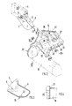
- Fig. 1 shows an exploded view of a portion of a body 1 of a passenger car.
- the car body 1 is composed of a front car 2, a floor or middle part 3 and a rear car 4 in the area shown.
- the front carriage 2, the bottom or middle part 3 and the rear carriage 4 form prefabricated structural units which are assembled during the assembly of the car body 1.
- the front end 2 includes two Front longitudinal members 5 which are arranged at a distance from one another and are connected to one another at their front ends in a manner not shown in detail by means of a cross member. At their rear ends, the front side members 5 are received in first node elements 6 and firmly connected to them. This can be done by welding, gluing, screwing, riveting or the like.
- the first, approximately shoe-shaped knot elements 6 encompass the front side member 5 from below, from behind and from both long sides in a positive manner. Towards the rear, the hollow element-like node elements 6 are closed on all sides. The two long sides 7, 8 of the node element 6 are recessed approximately L-shaped in the connection area with the front longitudinal beam 5 to 9 (FIG. 2).
- the bottom or middle part 3 is essentially composed of two sills 10 on the side, a center tunnel 11, a bottom 12 and a seat cross member 13. Furthermore, a second node element 14, which extends in the transverse direction of the vehicle, is provided on the front end region of the floor or middle part 3 and is fixedly connected to the sill 10, the floor 12 and the center tunnel 11.
- the second node element 14 has a channel-shaped receptacle 15 which extends in the extension of the front longitudinal beam 5 or the first node element 6 and into which the first node element 6 is inserted from above or from the front (FIG. 5).
- there is a connection between the two node elements 6, 14 by welding, gluing, screwing or the like.
- the trough-shaped receptacle 15 causes the first node element 8 to be automatically centered in the receptacle 15, since the receptacle (15) tapers continuously downwards when viewed in the transverse direction. (Draft angle).
- vertical wall sections 18, 19 which run obliquely and run away on both sides of the channel-shaped, longitudinal receptacle 15, one wall section 18 running to the central tunnel 11 and the other wall section 19 running in the direction of the sill 10.
- the last-mentioned wall section 19 opens into an end transverse wall 20 which closes the sill 10.
- Locally horizontal stiffening ribs are provided on the wall section 19.
- a turned-off edge 21 of this transverse wall 20 partially surrounds an edge region of the sill 10.
- a niche-shaped receiving space 22 is provided on the second node element 14, which, viewed in the vertical direction, is delimited by two spaced apart webs 23, 24.
- a threaded plate (not shown in more detail) can be inserted into this receiving space 22, to which a wishbone, also not shown, arranged below the second node element 14 can be fastened.
- the threaded plate can be inserted from the passenger compartment and extends approximately at the surface 17 of the receptacle 15.
- the second node element 14 has a stepped footwell section 26 on the side facing a passenger compartment 25.
- a pedal or a pedal series is screwed directly onto a horizontal surface of the stepped footwell section 26.
- two threaded bores 28 are provided on a base-like elevation 27 of the node element 14.
- the second node element 14 has a U-shaped edge 29 on the side facing the central tunnel 11, which surrounds a hollow profile section 30 of the central tunnel 11, wherein an additional connection between the edge 29 and the hollow profile section 30 can be provided (welding, gluing, screwing , Rivets or the like.).
- a double-walled floor 12 with locally arranged longitudinal webs 31 is connected to the second node element 14.
- An upper base plate 32 lies on the horizontal surface 33 of the node element 14, whereas a lower base plate 34 is supported and fastened on horizontal flanges 35, 36 of the node element 14.
- a step-shaped shelf 37 facing the passenger compartment 25 is provided with recesses 38 in the region of the longitudinal webs 31 of the floor 12, so that the webs 31 can be brought up to the upright wall sections 18, 19 of the node element 14 and are firmly connected thereto.
- a transverse gear carrier (not shown in detail) is provided below the second node element 14.
- the gear carrier rests on the underside of the second node element 14 and is clamped against the second node element 14 from below by a vertical fastening screw.
- the fastening screw is passed through a through opening 41 of the second node element 14 and screwed into a threaded bore 42 of the first node element located above it. There is thus an additional connection between the two node elements 6, 14.
- the threaded hole is arranged on the horizontal surface 16 of the node element 6.
- the front side member 5, the sill 10 and the center tunnel 11 are formed by hollow-profile extruded profiles made of light metal, whereas the node elements are designed as castings made of light metal.
Landscapes
- Engineering & Computer Science (AREA)
- Chemical & Material Sciences (AREA)
- Combustion & Propulsion (AREA)
- Transportation (AREA)
- Mechanical Engineering (AREA)
- Architecture (AREA)
- Structural Engineering (AREA)
- Body Structure For Vehicles (AREA)
Applications Claiming Priority (2)
| Application Number | Priority Date | Filing Date | Title |
|---|---|---|---|
| DE4013784 | 1990-04-28 | ||
| DE4013784A DE4013784C2 (de) | 1990-04-28 | 1990-04-28 | Wagenkasten, insbesondere für Personenkraftwagen |
Publications (2)
| Publication Number | Publication Date |
|---|---|
| EP0454942A1 true EP0454942A1 (fr) | 1991-11-06 |
| EP0454942B1 EP0454942B1 (fr) | 1993-03-17 |
Family
ID=6405392
Family Applications (1)
| Application Number | Title | Priority Date | Filing Date |
|---|---|---|---|
| EP91100665A Expired - Lifetime EP0454942B1 (fr) | 1990-04-28 | 1991-01-21 | Caisse de véhicule, en particulier pour voiture particulière |
Country Status (4)
| Country | Link |
|---|---|
| US (1) | US5112102A (fr) |
| EP (1) | EP0454942B1 (fr) |
| JP (1) | JPH04228375A (fr) |
| DE (2) | DE4013784C2 (fr) |
Cited By (10)
| Publication number | Priority date | Publication date | Assignee | Title |
|---|---|---|---|---|
| WO1992011168A1 (fr) * | 1990-12-20 | 1992-07-09 | Audi Ag | Liaison porteuse, notamment longeron porteur de liaison pour la carrosserie de voitures automobiles |
| WO1992022454A1 (fr) * | 1991-06-14 | 1992-12-23 | Audi Ag | Element portant de la carrosserie en metal leger de vehicules a moteur |
| DE19506160A1 (de) * | 1995-02-22 | 1996-08-29 | Opel Adam Ag | Rahmenkonstruktion für Kraftfahrzeuge |
| DE19618258A1 (de) * | 1996-05-07 | 1997-11-13 | Bayerische Motoren Werke Ag | Rahmen |
| EP0845405A1 (fr) * | 1996-11-29 | 1998-06-03 | Renault | Traverse de châssis de véhicule automobile |
| DE19931741A1 (de) * | 1999-07-08 | 2001-01-18 | Daimler Chrysler Ag | Kraftfahrzeugaufbau |
| DE102006038921A1 (de) * | 2006-08-18 | 2008-02-28 | Audi Ag | Hilfsrahmen für ein Kraftfahrzeug |
| WO2009149692A1 (fr) * | 2008-06-11 | 2009-12-17 | Ksm Casting Gmbh | Élément de gousset |
| CN109941350A (zh) * | 2017-12-20 | 2019-06-28 | 广州汽车集团股份有限公司 | 车身前部框架结构及汽车 |
| CN111497948A (zh) * | 2019-01-31 | 2020-08-07 | 广州汽车集团股份有限公司 | 一种车身纵梁接头结构及汽车 |
Families Citing this family (36)
| Publication number | Priority date | Publication date | Assignee | Title |
|---|---|---|---|---|
| US5383987A (en) * | 1990-12-20 | 1995-01-24 | Audi A.G. | Cast and assembly method for motor vehicle bodywork |
| DE4204826A1 (de) * | 1991-12-14 | 1993-06-17 | Porsche Ag | Wagenkasten fuer kraftfahrzeuge, insbesondere personenkraftwagen |
| DE4224489C3 (de) * | 1992-07-24 | 2002-02-21 | Audi Ag | Vorderer Längsträger für ein Kraftfahrzeug mit Strangpreßprofil aus Leichtmetall |
| DE19547241A1 (de) * | 1995-12-18 | 1997-06-19 | Bayerische Motoren Werke Ag | Trägeranordnung |
| DE19601315A1 (de) * | 1996-01-16 | 1997-07-17 | Bayerische Motoren Werke Ag | Knotenelement |
| DE19633908B4 (de) * | 1996-08-22 | 2008-01-10 | Bayerische Motoren Werke Ag | Bodengruppe für ein Fahrzeug |
| DE19753207C2 (de) | 1997-12-01 | 2002-09-12 | Daimler Chrysler Ag | Karosseriesegment für ein Fahrzeug |
| DE19816031B4 (de) * | 1998-04-09 | 2015-04-02 | Volkswagen Ag | Bodengruppe eines Personenkraftwagens |
| US6250711B1 (en) * | 1998-07-31 | 2001-06-26 | Toyota Jidosha Kabushiki Kaisha | Energy absorber securing structure and method |
| DE19909726B4 (de) * | 1999-03-05 | 2005-11-10 | Daimlerchrysler Ag | Rohbaubodenteil eines Kraftfahrzeuges |
| DE19916286A1 (de) * | 1999-04-12 | 2000-10-19 | Alstom Lhb Gmbh | Einrichtung zur Verstärkung der Ecken in Ausschnitten von orthogonal versteiften Wand-/Deckenbereichen |
| FR2800693B1 (fr) * | 1999-11-05 | 2001-12-07 | Renault | Corbeau de vehicule automobile |
| GB2387154B (en) * | 2000-04-05 | 2004-06-09 | Lotus Car | A method of manufacture of an automobile structure |
| FR2839491B1 (fr) * | 2002-05-07 | 2004-07-23 | Renault Sa | Noeud de connexion inferieur d'une ossature de base de vehicule automobile et son procede de montage |
| DE10224307B4 (de) * | 2002-05-31 | 2014-02-13 | Dr. Ing. H.C. F. Porsche Aktiengesellschaft | Tragstruktur für einen Kraftwagenaufbau |
| JP4196180B2 (ja) | 2003-04-09 | 2008-12-17 | 三菱自動車エンジニアリング株式会社 | 車体構造 |
| DE10340358A1 (de) * | 2003-09-02 | 2005-03-24 | Volkswagen Ag | Säulenknoten für eine Fahrzeugkarosserie |
| KR100644942B1 (ko) * | 2004-10-05 | 2006-11-10 | 현대자동차주식회사 | 차량 플로워의 하부 충돌 분산 구조 |
| DE102006014981A1 (de) * | 2006-03-31 | 2007-10-04 | Dr.Ing.H.C. F. Porsche Ag | Querträgerstruktur für einen Sitzbereich eines Fahrzeugs |
| JP5201864B2 (ja) * | 2007-03-30 | 2013-06-05 | 三菱自動車工業株式会社 | 車体構造 |
| DE102008009804A1 (de) * | 2008-02-19 | 2009-08-20 | Dr. Ing. H.C. F. Porsche Aktiengesellschaft | Bodenmittelteil einer Fahrzeugkarosserie |
| US8485591B2 (en) * | 2010-05-10 | 2013-07-16 | Honda Motor Co., Ltd. | Front vehicle body structure |
| FR2970459B1 (fr) * | 2011-01-18 | 2013-02-15 | Peugeot Citroen Automobiles Sa | Liaison entre le longeron interieur et le longeronnet avant de la caisse d'un vehicule automobile et vehicule ainsi equipe |
| DE102011077810B4 (de) * | 2011-06-20 | 2019-01-03 | Bayerische Motoren Werke Aktiengesellschaft | Karosserie eines Kraftfahrzeugs |
| DE102011089153A1 (de) * | 2011-12-20 | 2013-06-20 | Bayerische Motoren Werke Aktiengesellschaft | Aufbau für einen Kraftwagen, insbesondere einen Personenkraftwagen, sowie Verfahren zum Herstellen eines solchen Aufbaus |
| DE202012103583U1 (de) | 2012-09-19 | 2012-10-29 | Dr. Ing. H.C. F. Porsche Aktiengesellschaft | Verbindungsanordnung zwischen einer Fahrgastzelle einer Fahrzeugkarosserie und einem Längsträger |
| WO2014063687A2 (fr) * | 2012-10-24 | 2014-05-01 | Ksm Castings Group Gmbh | Système modulaire |
| DE102013107756A1 (de) * | 2013-07-19 | 2015-01-22 | Daimler Ag | Verstärkungsbauteil für eine Schutzeinrichtung einer Karosserie eines Personenkraftwagens |
| US9802654B2 (en) * | 2013-07-22 | 2017-10-31 | GM Global Technology Operations LLC | Method of assembling a vehicle uniframe |
| DE102014016045A1 (de) | 2014-10-29 | 2016-05-04 | GM Global Technology Operations LLC (n. d. Ges. d. Staates Delaware) | Fahrzeug-Unterbaustruktur |
| DE102015003128B4 (de) * | 2015-03-12 | 2019-09-05 | Daimler Ag | Verbindungsanordnung für eine Karosserie eines Personenkraftwagens |
| JP6642402B2 (ja) | 2016-12-09 | 2020-02-05 | トヨタ自動車株式会社 | 車両骨格構造 |
| DE102019211103A1 (de) | 2019-07-25 | 2021-01-28 | Volkswagen Aktiengesellschaft | Karosseriestruktur für ein elektrisch betriebenes Fahrzeug |
| DE102019211108A1 (de) * | 2019-07-25 | 2021-01-28 | Volkswagen Aktiengesellschaft | Karosseriestruktur für ein elektrisch betriebenes Fahrzeug |
| DE102019134712B4 (de) * | 2019-12-17 | 2021-09-02 | Dr. Ing. H.C. F. Porsche Aktiengesellschaft | Karosserieteilstruktur für ein wenigstens teilweise batteriebetriebenes Kraftfahrzeug |
| DE102022113070B3 (de) | 2022-05-24 | 2023-04-20 | Bayerische Motoren Werke Aktiengesellschaft | Karosseriestruktur für eine Karosserie eines Personenkraftwagens, Karosserie sowie Personenkraftwagen |
Citations (4)
| Publication number | Priority date | Publication date | Assignee | Title |
|---|---|---|---|---|
| GB659155A (en) * | 1948-05-27 | 1951-10-17 | Budd Co | Improvements in or relating to vehicle bodies |
| DE947677C (de) * | 1953-07-04 | 1956-08-23 | Daimler Benz Ag | Rahmen fuer Kraftfahrzeuge, insbesondere Personenwagen |
| FR2213664A5 (fr) * | 1973-01-05 | 1974-08-02 | Saviem | |
| EP0146716B1 (fr) * | 1983-12-24 | 1988-12-07 | Audi Ag | Superstructure |
Family Cites Families (9)
| Publication number | Priority date | Publication date | Assignee | Title |
|---|---|---|---|---|
| US3110518A (en) * | 1962-08-31 | 1963-11-12 | Budd Co | Unitized convertible underbody |
| DE2450763A1 (de) * | 1974-10-25 | 1976-04-29 | Volkswagenwerk Ag | Bodenrahmen fuer ein fahrzeug, insbesondere ein kraftfahrzeug |
| DE2725083C2 (de) * | 1977-06-03 | 1984-09-27 | Daimler-Benz Ag, 7000 Stuttgart | Längsträgerabstützung für eine selbsttragende Kraftwagen-Karosserie |
| SE7806168L (sv) * | 1977-06-03 | 1978-12-04 | Daimler Benz Ag | Anordning vid en till torpedveggen pa ett motorfordonskarosseri under nedatbockning anslutande lengsgaende frambalk |
| IT1128462B (it) * | 1980-05-19 | 1986-05-28 | Fiat Auto Spa | Struttura portante per autoveicolo |
| DE3114379C2 (de) * | 1981-04-09 | 1986-11-20 | Dr.Ing.H.C. F. Porsche Ag, 7000 Stuttgart | Aufbaustruktur eines Personenkraftwagens |
| DE3223156A1 (de) * | 1982-06-22 | 1983-12-22 | Dr.Ing.H.C. F. Porsche Ag, 7000 Stuttgart | Aufbau fuer kraftfahrzeuge, insbesondere personenkraftwagen |
| IT1213478B (it) * | 1986-08-07 | 1989-12-20 | Alfa Romeo Spa | Scocca per una vettur,a particolarmente una autovettura, eprocedimento per la sua realizzazione. |
| JPH0768521B2 (ja) * | 1987-10-07 | 1995-07-26 | 株式会社半導体エネルギー研究所 | 液晶電気光学装置 |
-
1990
- 1990-04-28 DE DE4013784A patent/DE4013784C2/de not_active Expired - Fee Related
-
1991
- 1991-01-21 EP EP91100665A patent/EP0454942B1/fr not_active Expired - Lifetime
- 1991-01-21 DE DE9191100665T patent/DE59100059D1/de not_active Expired - Fee Related
- 1991-04-22 US US07/688,270 patent/US5112102A/en not_active Expired - Fee Related
- 1991-04-23 JP JP3092055A patent/JPH04228375A/ja active Pending
Patent Citations (4)
| Publication number | Priority date | Publication date | Assignee | Title |
|---|---|---|---|---|
| GB659155A (en) * | 1948-05-27 | 1951-10-17 | Budd Co | Improvements in or relating to vehicle bodies |
| DE947677C (de) * | 1953-07-04 | 1956-08-23 | Daimler Benz Ag | Rahmen fuer Kraftfahrzeuge, insbesondere Personenwagen |
| FR2213664A5 (fr) * | 1973-01-05 | 1974-08-02 | Saviem | |
| EP0146716B1 (fr) * | 1983-12-24 | 1988-12-07 | Audi Ag | Superstructure |
Cited By (15)
| Publication number | Priority date | Publication date | Assignee | Title |
|---|---|---|---|---|
| WO1992011168A1 (fr) * | 1990-12-20 | 1992-07-09 | Audi Ag | Liaison porteuse, notamment longeron porteur de liaison pour la carrosserie de voitures automobiles |
| WO1992022454A1 (fr) * | 1991-06-14 | 1992-12-23 | Audi Ag | Element portant de la carrosserie en metal leger de vehicules a moteur |
| US5411308A (en) * | 1991-06-14 | 1995-05-02 | Audi A.G. | Girder assembly for a light alloy motor vehicle body |
| DE19506160B4 (de) * | 1995-02-22 | 2006-05-11 | Adam Opel Ag | Rahmenkonstruktion für Kraftfahrzeuge |
| DE19506160A1 (de) * | 1995-02-22 | 1996-08-29 | Opel Adam Ag | Rahmenkonstruktion für Kraftfahrzeuge |
| DE19618258A1 (de) * | 1996-05-07 | 1997-11-13 | Bayerische Motoren Werke Ag | Rahmen |
| EP0845405A1 (fr) * | 1996-11-29 | 1998-06-03 | Renault | Traverse de châssis de véhicule automobile |
| FR2756537A1 (fr) * | 1996-11-29 | 1998-06-05 | Renault | Traverse de chassis de vehicule automobile |
| DE19931741A1 (de) * | 1999-07-08 | 2001-01-18 | Daimler Chrysler Ag | Kraftfahrzeugaufbau |
| DE19931741B4 (de) * | 1999-07-08 | 2004-11-25 | Daimlerchrysler Ag | Kraftfahrzeugaufbau |
| DE102006038921A1 (de) * | 2006-08-18 | 2008-02-28 | Audi Ag | Hilfsrahmen für ein Kraftfahrzeug |
| DE102006038921B4 (de) * | 2006-08-18 | 2010-07-22 | Audi Ag | Hilfsrahmen für ein Kraftfahrzeug |
| WO2009149692A1 (fr) * | 2008-06-11 | 2009-12-17 | Ksm Casting Gmbh | Élément de gousset |
| CN109941350A (zh) * | 2017-12-20 | 2019-06-28 | 广州汽车集团股份有限公司 | 车身前部框架结构及汽车 |
| CN111497948A (zh) * | 2019-01-31 | 2020-08-07 | 广州汽车集团股份有限公司 | 一种车身纵梁接头结构及汽车 |
Also Published As
| Publication number | Publication date |
|---|---|
| US5112102A (en) | 1992-05-12 |
| EP0454942B1 (fr) | 1993-03-17 |
| DE59100059D1 (de) | 1993-04-22 |
| JPH04228375A (ja) | 1992-08-18 |
| DE4013784A1 (de) | 1991-11-07 |
| DE4013784C2 (de) | 1994-01-27 |
Similar Documents
| Publication | Publication Date | Title |
|---|---|---|
| DE4013784C2 (de) | Wagenkasten, insbesondere für Personenkraftwagen | |
| DE10023193B4 (de) | Fahrzeugaufbau für einen Vorderwagen eines Kraftfahrzeugs | |
| EP0146716B1 (fr) | Superstructure | |
| EP0563526B1 (fr) | Système de construction par gammes pour cabines de conducteur de camions | |
| DE4204826A1 (de) | Wagenkasten fuer kraftfahrzeuge, insbesondere personenkraftwagen | |
| EP1911662B1 (fr) | Fond de caisse d'un véhicule et système de plate-forme | |
| DE10038389A1 (de) | Motorhaubenstruktur für ein Fahrzeug | |
| DE4209879A1 (de) | Vordere karosseriestruktur eines fahrzeugs | |
| DE10239990A1 (de) | Kraftwagen-Karosserie mit einer Tragstruktur aus großformatigen Teilmodulen | |
| EP0702123B1 (fr) | Charnière de porte à arrêtoir de porte intégré pour portes de véhicules, l'arrêtoir comprenant une barre de torsion et élément d'arrêt | |
| DE19708215A1 (de) | Schweller eines Kraftfahrzeugs mit einer Verstärkungseinlage | |
| DE19913532A1 (de) | Kraftfahrzeugkarosserie sowie Versteifungsrahmen für eine Kraftfahrzeugkarosserie | |
| DE19939615B4 (de) | Sitzgestell für einen Sitz in Kraftfahrzeugen | |
| DE10047880A1 (de) | Fahrschemelkonstruktion | |
| DE8815885U1 (de) | Fahrzeugkarosserie | |
| EP1534577A1 (fr) | Carrosserie de voiture avec montant | |
| EP1170197A2 (fr) | Colonne centrale d'une carrosserie de véhicule automobile , comprenant au moins deux sections de colonne | |
| DE19709315C2 (de) | Sitzkonsole für einen Kraftfahrzeugsitz | |
| DE19651627B4 (de) | Unterbaustruktur einer Kraftfahrzeugkarosserie | |
| DE19943296C2 (de) | Fahrgastzelle für einen Personenkraftwagen | |
| DE10360170B3 (de) | Deformationselement für ein Kraftfahrzeug | |
| DE3114415C2 (de) | Aufbauendwand für Personenkraftwagen | |
| DE10302756B4 (de) | Tragstruktur für eine Kraftwagenkarosserie | |
| DE10001102A1 (de) | Karosserievorderbau für ein Kraftfahrzeug | |
| DE102006012528A1 (de) | Trägeranordnung für ein Fahrzeug |
Legal Events
| Date | Code | Title | Description |
|---|---|---|---|
| PUAI | Public reference made under article 153(3) epc to a published international application that has entered the european phase |
Free format text: ORIGINAL CODE: 0009012 |
|
| AK | Designated contracting states |
Kind code of ref document: A1 Designated state(s): DE FR GB IT SE |
|
| 17P | Request for examination filed |
Effective date: 19920313 |
|
| 17Q | First examination report despatched |
Effective date: 19920817 |
|
| ITF | It: translation for a ep patent filed | ||
| GRAA | (expected) grant |
Free format text: ORIGINAL CODE: 0009210 |
|
| AK | Designated contracting states |
Kind code of ref document: B1 Designated state(s): DE FR GB IT SE |
|
| REF | Corresponds to: |
Ref document number: 59100059 Country of ref document: DE Date of ref document: 19930422 |
|
| GBT | Gb: translation of ep patent filed (gb section 77(6)(a)/1977) |
Effective date: 19930401 |
|
| ET | Fr: translation filed | ||
| PLBE | No opposition filed within time limit |
Free format text: ORIGINAL CODE: 0009261 |
|
| STAA | Information on the status of an ep patent application or granted ep patent |
Free format text: STATUS: NO OPPOSITION FILED WITHIN TIME LIMIT |
|
| 26N | No opposition filed | ||
| PGFP | Annual fee paid to national office [announced via postgrant information from national office to epo] |
Ref country code: SE Payment date: 19950102 Year of fee payment: 5 |
|
| EAL | Se: european patent in force in sweden |
Ref document number: 91100665.8 |
|
| PGFP | Annual fee paid to national office [announced via postgrant information from national office to epo] |
Ref country code: FR Payment date: 19951228 Year of fee payment: 6 |
|
| PGFP | Annual fee paid to national office [announced via postgrant information from national office to epo] |
Ref country code: GB Payment date: 19960112 Year of fee payment: 6 |
|
| PGFP | Annual fee paid to national office [announced via postgrant information from national office to epo] |
Ref country code: DE Payment date: 19960115 Year of fee payment: 6 |
|
| PG25 | Lapsed in a contracting state [announced via postgrant information from national office to epo] |
Ref country code: SE Effective date: 19960122 |
|
| EUG | Se: european patent has lapsed |
Ref document number: 91100665.8 |
|
| PG25 | Lapsed in a contracting state [announced via postgrant information from national office to epo] |
Ref country code: GB Effective date: 19970121 |
|
| GBPC | Gb: european patent ceased through non-payment of renewal fee |
Effective date: 19970121 |
|
| PG25 | Lapsed in a contracting state [announced via postgrant information from national office to epo] |
Ref country code: FR Effective date: 19970930 |
|
| PG25 | Lapsed in a contracting state [announced via postgrant information from national office to epo] |
Ref country code: DE Effective date: 19971001 |
|
| REG | Reference to a national code |
Ref country code: FR Ref legal event code: ST |
|
| PG25 | Lapsed in a contracting state [announced via postgrant information from national office to epo] |
Ref country code: IT Free format text: LAPSE BECAUSE OF NON-PAYMENT OF DUE FEES;WARNING: LAPSES OF ITALIAN PATENTS WITH EFFECTIVE DATE BEFORE 2007 MAY HAVE OCCURRED AT ANY TIME BEFORE 2007. THE CORRECT EFFECTIVE DATE MAY BE DIFFERENT FROM THE ONE RECORDED. Effective date: 20050121 |