EP0454956A1 - Kupplung mit mehreren hintereinandergeschalteten Lamellenpaketen - Google Patents
Kupplung mit mehreren hintereinandergeschalteten Lamellenpaketen Download PDFInfo
- Publication number
- EP0454956A1 EP0454956A1 EP91102602A EP91102602A EP0454956A1 EP 0454956 A1 EP0454956 A1 EP 0454956A1 EP 91102602 A EP91102602 A EP 91102602A EP 91102602 A EP91102602 A EP 91102602A EP 0454956 A1 EP0454956 A1 EP 0454956A1
- Authority
- EP
- European Patent Office
- Prior art keywords
- flange
- flanges
- hub
- pair
- shaft
- Prior art date
- Legal status (The legal status is an assumption and is not a legal conclusion. Google has not performed a legal analysis and makes no representation as to the accuracy of the status listed.)
- Granted
Links
Images

Classifications
-
- F—MECHANICAL ENGINEERING; LIGHTING; HEATING; WEAPONS; BLASTING
- F16—ENGINEERING ELEMENTS AND UNITS; GENERAL MEASURES FOR PRODUCING AND MAINTAINING EFFECTIVE FUNCTIONING OF MACHINES OR INSTALLATIONS; THERMAL INSULATION IN GENERAL
- F16D—COUPLINGS FOR TRANSMITTING ROTATION; CLUTCHES; BRAKES
- F16D3/00—Yielding couplings, i.e. with means permitting movement between the connected parts during the drive
- F16D3/50—Yielding couplings, i.e. with means permitting movement between the connected parts during the drive with the coupling parts connected by one or more intermediate members
- F16D3/78—Yielding couplings, i.e. with means permitting movement between the connected parts during the drive with the coupling parts connected by one or more intermediate members shaped as an elastic disc or flat ring, arranged perpendicular to the axis of the coupling parts, different sets of spots of the disc or ring being attached to each coupling part, e.g. Hardy couplings
- F16D3/79—Yielding couplings, i.e. with means permitting movement between the connected parts during the drive with the coupling parts connected by one or more intermediate members shaped as an elastic disc or flat ring, arranged perpendicular to the axis of the coupling parts, different sets of spots of the disc or ring being attached to each coupling part, e.g. Hardy couplings the disc or ring being metallic
-
- F—MECHANICAL ENGINEERING; LIGHTING; HEATING; WEAPONS; BLASTING
- F16—ENGINEERING ELEMENTS AND UNITS; GENERAL MEASURES FOR PRODUCING AND MAINTAINING EFFECTIVE FUNCTIONING OF MACHINES OR INSTALLATIONS; THERMAL INSULATION IN GENERAL
- F16D—COUPLINGS FOR TRANSMITTING ROTATION; CLUTCHES; BRAKES
- F16D3/00—Yielding couplings, i.e. with means permitting movement between the connected parts during the drive
- F16D3/50—Yielding couplings, i.e. with means permitting movement between the connected parts during the drive with the coupling parts connected by one or more intermediate members
- F16D3/60—Yielding couplings, i.e. with means permitting movement between the connected parts during the drive with the coupling parts connected by one or more intermediate members comprising pushing or pulling links attached to both parts
-
- F—MECHANICAL ENGINEERING; LIGHTING; HEATING; WEAPONS; BLASTING
- F16—ENGINEERING ELEMENTS AND UNITS; GENERAL MEASURES FOR PRODUCING AND MAINTAINING EFFECTIVE FUNCTIONING OF MACHINES OR INSTALLATIONS; THERMAL INSULATION IN GENERAL
- F16D—COUPLINGS FOR TRANSMITTING ROTATION; CLUTCHES; BRAKES
- F16D3/00—Yielding couplings, i.e. with means permitting movement between the connected parts during the drive
- F16D3/50—Yielding couplings, i.e. with means permitting movement between the connected parts during the drive with the coupling parts connected by one or more intermediate members
- F16D3/72—Yielding couplings, i.e. with means permitting movement between the connected parts during the drive with the coupling parts connected by one or more intermediate members with axially-spaced attachments to the coupling parts
Definitions
- the invention relates to an all-steel coupling for connecting a shaft to a hub consisting of two coaxially arranged series pairs of flanges, one flange of which is connected to the shaft or hub and the other flanges of which are rigidly connected together by means of a sleeve, and two disk pack rings, each associated with a pair of flanges , which are connected alternately circumferentially to one or the other flange of the respective flange pair, with an adapter which extends in the direction of the hub and which is concentrically, radially fixed and axially movably mounted on the flange connected to the shaft.
- a coupling of this type is known from German utility model 7100034.
- Such a coupling has the advantage that it is connected in series because of the Multi-plate pack rings allow a greater axial displacement than with couplings with a multi-plate pack ring without inadmissibly high bending or tensile stresses occurring in the plates.
- two pairs of flanges are provided, the one flange connection assigned to the shaft being able to accommodate only axial displacement, whereas the second flange connection assigned to the hub can also additionally cope with angular displacement.
- the flange connection assigned to the shaft is fixed in such a way that it can only accommodate axial misalignment, but not angular misalignment, is carried out by means of an intermediate piece which is integrally formed on the flange connected to the shaft and which is axially displaceably mounted in a sleeve in the known object by means of a bearing bush is.
- the arrangement of the bearing in the known all-steel clutch is provided within the area bounded by the sleeve and enclosed by the two disk pack rings.
- a bearing, as provided in the known object, is, on the one hand, complex to assemble and, on the other hand, its storage properties can change during operation. This can lead to instabilities or functional impairments in couplings with the known structure.
- the invention has for its object to further develop a coupling of the type mentioned in such a way that the storage of the intermediate piece is structurally simpler and improved in terms of their functional reliability.
- this object is achieved in that the bearing for the intermediate piece is formed by a radially extending transverse lamella arrangement.
- the transverse lamella arrangement fulfills the function of a bearing which is flexible in the axial direction but rigid in the radial direction.
- a preferred embodiment of this first variant is obtained if the lamella arrangement is formed by three star-shaped colliding lamella packages, in the center space of which the intermediate piece is fastened by means of a screw connection.
- the star-shaped lamella arrangement results in a particularly high degree of flexibility in the axial direction, while the bearing is designed radially without play.
- the first variant of the invention described shows optimal behavior when the transverse lamella arrangement is arranged in the immediate vicinity of the flange pair assigned to the hub.
- the manufacturing outlay for installing the cross plate pack is only very low, because existing construction elements can also be used.
- the bearing for the intermediate piece is formed by a holding part, the flange of which forms a further flange pair with a flange surface formed in the sleeve, the flanges of which are connected alternately in terms of circumference to a further plate pack ring.
- a further disk pack ring is provided, which is used to form the axially flexible, radially but rigid bearing.
- a separate design of the bearing seat as in the known clutch is also omitted in this variant.
- This variant is also characterized by a particularly robust design, which increases its service life.
- conventional construction elements such as steel lamellae and bolt connections can be used.
- the intermediate piece is connected to the holding part by means of a press connection, there is the additional advantage that the intermediate piece can first be inserted loosely into the holding part during installation and is then held in it by forming the press connection. This noticeably facilitates the assembly of the clutch.
- a special design for the press connection results from the fact that the press connection is formed from a coupling ring with a conical inner surface, the slope of which corresponds to a conical area on the outer surface of the holding part, the coupling ring being displaceable in this way against the outer surface of the holding part by screws provided in the holding part is that the surface pressure on the Intermediate piece is increased.
- This particular embodiment serves to further facilitate the assembly of the coupling according to the invention.
- FIG. 1a An exemplary embodiment of the first variant of the all-steel coupling according to the invention is shown with reference to FIG. 1a.
- the connection between the shaft 1 and the hub 2 takes place via a sleeve 5, which forms one flange 3a, 4b, two flange pairs 3a, 3b; 4a, 4b with the one flanges 3a, 4b.
- the flange pairs 3a, 3b and 4a, 4b are arranged coaxially to one another and mechanically connected in series.
- a plate pack ring 3c or 4c is assigned to a pair of flanges 3a, 3b; 4a, 4b.
- the disk pack rings 3c, 4c are connected circumferentially alternately to one or the other flange of the respective flange pair 3a, 3b; 4a, 4b.
- the front of the intermediate piece 6 directed towards the hub 2 carries a pin with a thread, which by means of a nut is fastened in a star-shaped transverse lamella arrangement 12a, 12b, 12c shown in FIG. 1b.
- the transverse disk arrangement 12a, 12b, 12c consists of intersecting disk packs 12a, 12b, 12c, each corresponding in length to approximately half the coupling diameter, the common end of which coincide with the connection point of the journal of the intermediate piece 6 and the separate ends of which are held by holding points 13a, 13c, 13b are formed.
- breakpoints are also breakpoints for the disk pack ring 3c assigned to the hub 2 insofar as these connection points represent the disk pack ring 3c and the flange 3b of the sleeve 5.
- the all-steel coupling arrangement described in FIGS. 1a and 1b is characterized in that the connection formed on the flange pairs 4a, 4b can only accommodate axial displacement, while the connection formed in the region of the flange pairs 3a, 3b can also compensate for angular displacement.
- This property can be achieved in that the flange connection in the region of the pair of flanges 4a, 4b is determined by the radial rigidity of the bearing formed by the transverse plate arrangement 7.
- the clutch according to the invention can absorb a noticeable axial offset without the plate packs being overloaded.
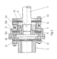
- the second variant according to the invention is explained in more detail with reference to FIG.
- Common structural elements with the exemplary embodiment of the first variant shown in FIGS. 1a, 1b are provided with the corresponding reference numerals in FIG.
- a sleeve 5 is provided which rigidly connects the flanges 3b, 4a facing each other.
- the sleeve 5 is shaped such that it comprises a flange surface 10b.
- This flange surface 10b forms with a flange 10a of a holding part 9 a further, third pair of flanges.
- the holding part 9 is connected via a coupling ring 14 to the pin-shaped tip of the intermediate piece 6 in the manner of a press wedge connection.
- the surface pressure between the pin of the intermediate piece 6 and the holding part 9 can be increased so that the intermediate piece is firmly clamped in the holding part 9.
- the pair of flanges 10a, 10b is circumferentially alternately coupled to a further, third plate pack ring 11 by means of a bolt connection.
- the function of the illustrated embodiment according to the second variant of the invention is essentially equivalent to the function of the embodiment of the first variant.
- the flange connection 4a, 4b only absorbs axial misalignment, while the flange connection 3a, 3b additionally also absorbs angular misalignment.
- the flange connection 10a, 10b serves as a suspension for the intermediate piece 6 via the third disk packet ring 11. On the one hand, this suspension ensures an axial flexibility of the intermediate piece 6, but on the other hand a radially rigid guidance, since the slats do not yield in this direction.
Landscapes
- Engineering & Computer Science (AREA)
- General Engineering & Computer Science (AREA)
- Mechanical Engineering (AREA)
- Mechanical Operated Clutches (AREA)
- Packaging For Recording Disks (AREA)
- Automatic Disk Changers (AREA)
- Rolling Contact Bearings (AREA)
Abstract
Description
- Die Erfindung betrifft eine Ganzstahlkupplung zur Verbindung einer Welle mit einer Nabe bestehend aus zwei koaxial zueinander angeordneten hintereinandergeschalteten Flanschpaaren, deren eine Flansche mit Welle bzw. Nabe verbunden sind und deren andere Flansche gemeinsam mittels einer Hülse starr verbunden sind, und zwei jeweils einem Flanschpaar zugeordneten Lamellenpaketkränzen, die umfangsmäßig abwechselnd mit dem einen bzw. anderen Flansch des jeweiligen Flanschpaares verbunden sind, wobei an dem mit der Welle verbundenen Flansch ein sich in Richtung auf die Nabe erstreckendes Zwischenstück angeformt ist, welches konzentrisch, radial festgelegt un axial beweglich gelagert ist.
- Eine Kupplung dieser Art ist aus dem deutschen Gebrauchsmuster 7100034 bekannt. Eine solche Kupplung hat den Vorteil, daß sie aufgrund der hintereinandergeschalteten Lamellenpaketkränze eine größere axiale Verschiebung zuläßt, als bei Kupplungen mit einem Lamellenpaketkranz, ohne daß in den Lamellen unzulässig hohe Biege- bzw. Zugbeanspruchungen auftreten. Bei der bekannten Kupplung sind zwei Flanschpaare vorgesehen, wobei die eine der Welle zugeordnete Flanschverbindung nur Axialversatz aufnehmen kann, wo hingegen die zweite, der Nabe zugeordnete Flanschverbindung, zusätzlich auch Winkelversatz bewältigen kann.
- Die Festlegung der der Welle zugeordneten Flanschverbindung in einer Weise, daß sie nur Axialversatz, nicht aber Winkelversatz aufnehmen kann, erfolgt durch ein an den einen mit der Welle verbundenen Flansch angeformtes Zwischenstück, welches bei dem bekannten Gegenstand mittels einer Lagerbuchse in einer Hülse axial verschieblich gelagert ist. Die Anordnung des Lagers bei der bekannten Ganzstahlkupplung ist innerhalb des durch die beiden Lamellenpaketkränze eingeschlossenen durch die Hülse begrenzten Bereiches vorgesehen.
- Ein Lager, wie es bei dem bekannten Gegenstand vorgesehen ist, ist jedoch zum einen aufwendig beim Zusammenbau und zum anderen können sich seine Lagereigenschaften im Laufe des Betriebes verändern. Dadurch kann es bei Kupplungen mit dem bekannten Aufbau zu Instabilitäten bzw. Funktionsbeeinträchtigungen kommen.
- Demgegenüber liegt der Erfindung die Aufgabe zugrunde, eine Kupplung der eingangs genannten Art derart weiterzuentwickeln, daß die Lagerung des Zwischenstückes konstruktiv einfacher und hinsichtlich ihrer Funktionssicherheit verbessert wird.
- Gemäß der Erfindung sind ausgehend von dieser Aufgabenstellung zwei Lösungen vorgesehen.
- Zum einen wird diese Aufgabe dadurch gelöst, daß das Lager für das Zwischenstück durch eine sich radial erstreckende Querlamellenanordnung gebildet ist.
- Bei dieser erfindungsgemäßen ersten Variante erfüllt die Querlamellenanordnung die Funktion eines in axialer Richtung nachgiebigen, in radialer Richtung jedoch starren Lagers.
- Besondere Maßnahmen, um die Axialbeweglichkeit des Lagers zu erhalten, beispielsweise eine Schmierung, oder das Vorsehen von Kunststoff-Führungsbuchsen, können bei dieser Variante der Erfindung entfallen. Vielmehr wird die axiale Nachgiebigkeit ausschließlich durch die Federelastizität der Querlamellen gewährleistet.
- Eine bevorzugte Ausbildung dieser ersten Variante ergibt sich, wenn die Lamellenanordnung durch drei sternförmig zusammenstoßende Lamellenpakete gebildet ist, in deren Zentraum das Zwischenstück mittels einer Schraubverbindung befestigt ist. Durch die sternförmige Lamellenanordnung ergibt sich eine besonders große Nachgiebigkeit in axialer Richtung, während das Lager radial ohne Spiel ausgeführt ist.
- Hinsichtlich der Stabilität zeigt die beschriebene erste Variante der Erfindung ein optimales Verhalten, wenn die Querlamellenanordnung in unmittelbarer Nähe des der Nabe zugeordneten Flanschpaares angeordnet ist.
- Wenn darüber hinaus die Querlamellenanordnung an den Haltepunkten für den der Habe zugeordneten Lamellenpaketkranz befestigt ist, ist der fertigungstechnische Aufwand für den Einbau des Querlamellenpaketes nur noch sehr gering, weil bereits bestehende Konstruktionselemente mitverwendet werden können.
- Die genannte Aufgabe wird bei einer zweiten Variante der Erfindung dadurch gelöst, daß das Lager für das Zwischenstück durch ein Halteteil gebildet ist, dessen Flansch mit einer in der Hülse angeformten Flanschfläche ein weiteres Flanschpaar bildet, dessen Flansche umfangsmäßig abwechselnd mit einem weiteren Lamellenpaketkranz verbunden sind.
- Gemäß dieser Variante ist neben den auch bei der bekannten Kupplung verwendeten Lamellenpaketkränzen ein weiterer Lamellenpaketkranz vorgesehen, der zur Ausbildung des axial nachgiebigen radial jedoch starren Lagers dient. Eine gesonderte Ausbildung des Lagersitzes wie bei der bekannten Kupplung entfällt auch bei dieser Variante. Diese Varainte zeichnet sich zudem durch eine besonders robuste Bauform aus, wodurch deren Lebensdauer erhöht wird. Für die Ausbildung der Aufhängung für das Zwischenstück gemäß der zweiten Variante der Erfindung können übliche Konstruktionselemente wie Stahllamellen und Bolzenverschraubungen verwendet werden.
- Wenn das Zwischenstück mittels einer Preßverbindung mit dem Halteteil verbunden ist, ergibt sich der zusätzliche Vorteil, daß das Zwischenstück beim Einbau zunächst in das Halteteil lose eingeschoben werden kann und anschließend durch Ausbildung der Preßverbindung in ihm gehalten wird. Dies erleichtert den Zusammenbau der Kupplung merklich.
- Eine besondere Ausführung für die Preßverbindung ergibt sich dadurch, daß die Preßverbindung aus einem Überwurfring mit einer konischen Innenfläche gebildet ist, deren Steigung einem konischen Bereich an der Außenfläche des Halteteils entspricht, wobei der Überwurfring durch im Halteteil vorgesehene Schrauben derart gegen die Außenfläche des Halteteils verschiebbar ist, daß die Flächenpressung auf das Zwischenstück erhöht wird. Diese besondere Ausführungsform dient zu einer weiteren Erleichterung des Zusammenbaus der erfindungsgemäßen Kupplung.
- Die Erfindung wird im folgenden anhand einer die beiden Varianten der erfindungsgmäßen Lösung darstellenden Zeichnung näher erläutert.
- Dabei zeigen:
- Fig. 1a
- einen Längsschnitt durch ein Ausführungsbeispiel gemäß der ersten Variante der Erfindung.
- Fig. 1b
- einen Schnitt entlang der Linie AB in Fig.1a und
- Fig. 2
- einen Schnitt durch ein Ausführungsbeispiel gemäß der zweiten Variante der Erfindung.
- Unter Bezug auf Fig. 1a ist ein Ausführungsbeispiel der ersten Variante der erfindungsgemäßen Ganzstahlkupplung dargestellt. Die Verbindung zwischen der Welle 1 und der Nabe 2 erfolgt über eine Hülse 5, welche mit den der Welle 1 bzw. der Habe 2 zugeordneten einen Flansche 3a,4b, zwei Flanschpaare 3a,3b;4a,4b bildet. Die Flanschpaare 3a,3b bzw. 4a,4b sind koaxial zueinander angeordnet und mechanisch hintereinandergeschaltet. Jeweils einem Flanschpaar 3a,3b;4a,4b ist ein Lamellenpaketkranz 3c bzw. 4c zugeordnet. Die Lamellenpaketkränze 3c, 4c, sind jeweils umfangsmäßig abwechselnd mit dem einen bzw. anderen Flansch des jeweiligen Flanschpaares 3a,3b;4a,4b verbunden.
- An den einen mit der Welle 1 verbundenen Flansch 4b ist ein sich in Richtung auf die Nabe 2 erstreckendes Zwischenstück 6 in Form einer zylindrischen Welle angeformt. Die auf die Nabe 2 gerichtete Vorderseite des Zwischenstückes 6 trägt einen Zapfen mit einem Gewinde, welcher mittels einer Mutter in einem in Fig. 1b dargestellten sternförmig ausgebildeten Querlamellenanordnung 12a,12b,12c befestigt ist. Die Querlamellenanordnung 12a,12b,12c besteht aus sich sternförmig kreuzenden, in ihrer Länge jeweils etwa der Hälfte des Kupplungsdurchmessers entsprechenden Lamellenpaketen 12a,12b,12c, deren gemeinsames Ende mit dem Anschlußpunkt des Zapfens des Zwischenstücks 6 zusammenfallen und deren getrennte Enden durch Haltepunkte 13a,13c,13b gebildet werden.
- Diese Haltepunkte sind gemeinsam auch Haltepunkte für den der Nabe 2 zugeordneten Lamellenpaketkranz 3c soweit diese Verbindungspunkte zwischen dem Lamellenpaketkranz 3c und dem Flansch 3b der Hülse 5 darstellen.
- Die in den Fig. 1a und 1b beschriebene Ganzstahlkupplungsanordnung zeichnet sich dadurch aus, daß die an den Flanschpaaren 4a,4b gebildete Verbindung nur Axialversatz aufnehmen kann, während die im Bereich der Flanschpaare 3a,3b gebildete Verbindung zusätzlich auch Winkelversatz ausgleichen kann. Diese Eigenschaft läßt sich dadurch erzielen, daß die Flanschverbindung im Bereich des Flanschpaares 4a,4b durch die radiale Starrheit des durch die Querlamellenanordnung 7 gebildeten Lagers festgelegt ist. Demgegenüber kann die erfindungsgemäße Kupplung einen merklichen Axialversatz aufnehmen, ohne daß es zu einer Überlastung der Lamellenpakete kommt.
- Unter Bezugnahme auf Fig.2 wird die zweite Variante gemäß der Erfindung näher erläutert. Gemeinsame konstruktive Elemente mit dem in Fig.1a,1b dargestellten Ausführungsbeispiel der ersten Variante sind in Fig.2 mit den entsprechenden Bezugszeichen versehen. So ist auch gemäß dem Ausführungsbeispiel der zweiten Variante zwischen den beiden der Welle 1 bzw. der Nabe zugeordneten Flanschpaaren 3a,3b bzw. 4a,4b eine Hülse 5 vorgesehen, die die einander zugewandten Flansche 3b,4a starr verbindet. Im Gegensatz zu dem in Fig. 1a und 1b dargestellten Ausführungsbeispiel ist die Hülse 5 so geformt, daß sie eine Flanschfläche 10b umfaßt. Diese Flanschfläche 10b bildet mit einem Flansch 10a eines Halteteiles 9 ein weiteres, drittes Flanschpaar.
- Das Halteteil 9 ist über einen Überwurfring 14 mit der zapfenförmig ausgebildeten Spitze des Zwischenstückes 6 in der Art einer Preßkeilverbindung verbunden.
- Über im Halteteil vorgesehene Schrauben läßt sich die Flächenpressung zwischen dem Zapfen des Zwischenstückes 6 und dem Halteteil 9 so erhöhen, daß das Zwischenstück fest im Halteteil 9 eingespannt ist. Das Flanschpaar 10a, 10b ist umfangsmäßig abwechselnd mit einem weiteren, dritten Lamellenpaketkranz 11 mittels Schraubenbolzenverbindung gekoppelt.
- Die Funktion des dargestellten Ausführungsbeispiels gemäß der zweiten Variante der Erfindung ist im wesentlichen äquivalent zu der Funktion des Ausführungsbeispiels der ersten Variante. Hierbei nimmt ebenfalls die Flanschverbindung 4a,4b nur Axialversatz auf, während die Flanschverbindung 3a,3b zusätzlich auch Winkelversatz aufnimmt. Die Flanschverbindung 10a,10b dient über den dritten Lamellenpaketkranz 11 als Aufhängung für das Zwischenstück 6. Diese Aufhängung gewährleistet einerseits eine axiale Nachgiebigkeit des Zwischenstückes 6 andererseits jedoch eine radial starre Führung, da die Lamellen in dieser Richtung nicht nachgeben.
- Es ist auch denkbar, daß die Zwischenwelle 6 über andere bekannte Dämpfungseinrichtungen, wie Reibung oder Luftdämpfung mit dem Anschlußflansch 10b im Bereich der Hülse 5 verbunden werden kann. Auf diese Weise lassen sich unter Erhaltung der axialen Nachgiebigkeit unerwünschte Schwingungen des Zwischenstückes 6 in axialer Richtung verhindern.
Claims (7)
- Ganzstahlkupplung zur Verbindung einer Welle (1) mit einer Nabe (2) bestehend aus zwei koaxial zueinander angeordneten hintereinandergeschalteten Flanschpaaren (3a,3b,4a,4b), deren eine Flansche (3a,4b) mit Welle (1) bzw. Nabe (2) verbunden sind und deren andere Flansche (3b,4a) gemeinsam mittels einer Hülse (5) starr verbunden sind, und zwei jeweils einem Flanschpaar (3a,3b,4a,4b) zugeordneten Lamellenpaketkränzen (3c,4c), die umfangsmäßig abwechselnd mit dem einen bzw. anderen Flansch des jeweiligen Flanschpaares (3a,3b,4a,4b) verbunden sind, wobei an dem mit der Welle (1) verbundenen Flansch (4b) ein sich in Richtung auf die Nabe (2) erstreckendes Zwischenstück (6) angeformt ist, welches konzentrisch, radial festgelegt und axial beweglich gelagert ist,
dadurch gekennzeichnet, daß das Lager für das Zwischenstück (6) durch eine sich radial erstreckende Querlamellenanordnung (7) gebildet ist. - Ganzstahlkupplung zur Verbindung einer Welle (1) mit einer Nabe (2) bestehend aus zwei koaxial zueinander angeordneten hintereinandergeschalteten Flanschpaaren (3a,3b,4a,4b), deren eine Flansche (3a,4b) mit Welle (1) bzw. Nabe (2) verbunden sind und deren Flansche (3b,4a) gemeinsam mittels einer Hülse (5) starr verbunden sind, und zwei jeweils einem Flanschpaar (3a,3b,4a,4b) zugeordneten Lamellenpaketkränzen (3c,4c), die umfangsmäßig abwechselnd mit dem einen bzw. anderen Flansch des jeweiligen Flanschpaares (3a,3b,4a,4b) verbunden sind, wobei an dem mit der Welle (1) verbunden Flansch (4b) ein sich in Richtung auf die Habe (2) erstreckendes Zwischenstück (6) angeformt ist, welches konzentrisch, radial festgelegt und axial beweglich gelagert ist,
dadurch gekennzeichnet, daß das Lager für das Zwischenstück (6) durch ein Halteteil (9) gebildet ist, dessen Flansch (10a) mit einer in der Hülse (5) eingeformten Flanschfläche (10b) ein weiteres Flanschpaar (10a,10b) bildet, dessen Flansche (10a,10b) umfangsmäßig abwechselnd mit einem weiteren Lamellenpaketkranz (11) verbunden sind. - Ganzstahlkupplung nach Anspruch 1,
dadurch gekennzeichnet, daß die Querlamellenanordnung (7) durch drei sternförmig zusammenstoßende Lamellenpakete (12a,12b,12c) gebildet ist, in deren Zentrum das Zwischenstück (6) mittels einer Schraubverbindung befestigt ist. - Ganzstahlkupplung nach Anspruch 1 oder 3,
dadurch gekennzeichnet, daß die Querlamellenanordnung (7,12a-c) in unmittelbarer Nähe des, der Habe (2) zugeordneten Flanschpaares (3a,3b) angeordnet ist. - Ganzstahlkupplung nach einem der Ansprüche 1,3,4
dadurch gekennzeichnet, daß die Querlamellenanordnung (7,12a-c) an Haltepunkten (13a,13b,13c) für den der Nabe (2) zugeordneten Lamellenpaketkranz (3c) befestigt ist. - Ganzstahlkupplung nach Anspruch 2,
dadurch gekennzeichnet, daß das Zwischenstück (6) mittels einer Preßverbindung (14) mit dem Halteteil (9) verbunden ist. - Ganzstahlkupplung nach Anspruch 2 oder 6,
dadurch gekennzeichnet, daß die Preßverbindung aus einem Überwurfring (14) mit einer konischen Innenfläche gebildet ist, deren Steigung einem konischen Bereich an der Außenfläche des Halteteils (9) entspricht, wobei der Überwurfring (14) durch im Kalteteil (9) vorgesehene Schrauben derart gegen die Außenfläche des Halteteils (9) verschiebbar ist, daß die Flächenpressung auf das Zwischenstück (6) erhöhbar ist.
Priority Applications (1)
| Application Number | Priority Date | Filing Date | Title |
|---|---|---|---|
| AT91102602T ATE94954T1 (de) | 1990-04-28 | 1991-02-22 | Kupplung mit mehreren hintereinandergeschalteten lamellenpaketen. |
Applications Claiming Priority (2)
| Application Number | Priority Date | Filing Date | Title |
|---|---|---|---|
| DE4013716 | 1990-04-28 | ||
| DE4013716A DE4013716A1 (de) | 1990-04-28 | 1990-04-28 | Kupplung mit mehreren hintereinandergeschalteten lamellenpaketen |
Publications (2)
| Publication Number | Publication Date |
|---|---|
| EP0454956A1 true EP0454956A1 (de) | 1991-11-06 |
| EP0454956B1 EP0454956B1 (de) | 1993-09-22 |
Family
ID=6405350
Family Applications (1)
| Application Number | Title | Priority Date | Filing Date |
|---|---|---|---|
| EP91102602A Expired - Lifetime EP0454956B1 (de) | 1990-04-28 | 1991-02-22 | Kupplung mit mehreren hintereinandergeschalteten Lamellenpaketen |
Country Status (3)
| Country | Link |
|---|---|
| EP (1) | EP0454956B1 (de) |
| AT (1) | ATE94954T1 (de) |
| DE (2) | DE4013716A1 (de) |
Cited By (3)
| Publication number | Priority date | Publication date | Assignee | Title |
|---|---|---|---|---|
| NL1003103C2 (nl) * | 1995-05-19 | 1999-01-19 | Stober & Morlock | Gasturbine-installatie. |
| RU2449186C1 (ru) * | 2011-03-02 | 2012-04-27 | Владимир Дмитриевич Анохин | Муфта |
| RU2453745C1 (ru) * | 2011-03-02 | 2012-06-20 | Владимир Дмитриевич Анохин | Муфта пластинчатая |
Families Citing this family (1)
| Publication number | Priority date | Publication date | Assignee | Title |
|---|---|---|---|---|
| DE19614267A1 (de) * | 1996-04-11 | 1997-10-16 | Atec Weiss Gmbh & Co Kg | Elastische, axial- und winkelbewegliche Kupplung |
Citations (2)
| Publication number | Priority date | Publication date | Assignee | Title |
|---|---|---|---|---|
| FR85477E (fr) * | 1964-03-17 | 1965-08-20 | Hispano Suiza Sa | Perfectionnements apportés aux dispositifs d'accouplement angulaire pour organes tournants, notamment pour arbres tubulaires disposés bout à bout |
| DE9004886U1 (de) * | 1990-04-30 | 1990-06-28 | Atec-Weiss GmbH & Co. KG, 4426 Vreden | Ganzstahlkupplung mit mindestens zwei hintereinander geschalteten Flanschpaaren |
Family Cites Families (2)
| Publication number | Priority date | Publication date | Assignee | Title |
|---|---|---|---|---|
| DE7100034U (de) * | 1972-10-12 | Atec Weiss Kg | Flanschkupplung zur Übertragung von Drehmomenten mit mindestens zwei koaxial hintereinander angeordneten Flanschpaaren | |
| US4416645A (en) * | 1982-01-13 | 1983-11-22 | Rexnord Inc. | Piloted flexible coupling |
-
1990
- 1990-04-28 DE DE4013716A patent/DE4013716A1/de active Granted
-
1991
- 1991-02-22 DE DE91102602T patent/DE59100393D1/de not_active Expired - Lifetime
- 1991-02-22 EP EP91102602A patent/EP0454956B1/de not_active Expired - Lifetime
- 1991-02-22 AT AT91102602T patent/ATE94954T1/de not_active IP Right Cessation
Patent Citations (2)
| Publication number | Priority date | Publication date | Assignee | Title |
|---|---|---|---|---|
| FR85477E (fr) * | 1964-03-17 | 1965-08-20 | Hispano Suiza Sa | Perfectionnements apportés aux dispositifs d'accouplement angulaire pour organes tournants, notamment pour arbres tubulaires disposés bout à bout |
| DE9004886U1 (de) * | 1990-04-30 | 1990-06-28 | Atec-Weiss GmbH & Co. KG, 4426 Vreden | Ganzstahlkupplung mit mindestens zwei hintereinander geschalteten Flanschpaaren |
Cited By (3)
| Publication number | Priority date | Publication date | Assignee | Title |
|---|---|---|---|---|
| NL1003103C2 (nl) * | 1995-05-19 | 1999-01-19 | Stober & Morlock | Gasturbine-installatie. |
| RU2449186C1 (ru) * | 2011-03-02 | 2012-04-27 | Владимир Дмитриевич Анохин | Муфта |
| RU2453745C1 (ru) * | 2011-03-02 | 2012-06-20 | Владимир Дмитриевич Анохин | Муфта пластинчатая |
Also Published As
| Publication number | Publication date |
|---|---|
| DE4013716C2 (de) | 1992-02-13 |
| DE59100393D1 (de) | 1993-10-28 |
| ATE94954T1 (de) | 1993-10-15 |
| EP0454956B1 (de) | 1993-09-22 |
| DE4013716A1 (de) | 1991-11-07 |
Similar Documents
| Publication | Publication Date | Title |
|---|---|---|
| DE2645600C3 (de) | Drehsteife und Wellenverlagerungen zulassende bewegliche Kupplung | |
| DE69902763T2 (de) | Drehfeste, spielfreie, elastische balgkupplung zur drehmomentübertragung zwischen zwei wellen | |
| EP0164792B1 (de) | Vorrichtung zum kraftschlüssigen Verbinden zweier Wellen | |
| EP0611895A2 (de) | Doppelmembrankupplung | |
| EP0816703A2 (de) | Konusschraubverbindung für Lamellenpaket-Wellenkupplungen | |
| DE102016216274A1 (de) | Riemenscheibenentkoppler mit Doppelnabe | |
| DE2036006A1 (de) | Getriebe mit schwimmendem Hauptantriebs zahnrad | |
| EP0454956B1 (de) | Kupplung mit mehreren hintereinandergeschalteten Lamellenpaketen | |
| DE3314322A1 (de) | Kreuzgelenk fuer eine gelenkwelle | |
| EP1379793A1 (de) | Kupplung zum verbinden zweier bauteile | |
| DE1221857B (de) | Gleichgang-Gelenkkupplung | |
| DE102005053362B4 (de) | Zentrieranordnung an einem Doppelkreuzgelenk | |
| EP1719928B1 (de) | Axialsicherungsanordnung für eine Lagerbüchse bei einem Kreuzgelenk | |
| AT521020B1 (de) | Kupplungsscheibe | |
| DE10346343B4 (de) | An einer Radnabe befestigbare Bremsscheibe | |
| EP0724087A1 (de) | Ganzstahlkupplung für Axialkraftübertragung | |
| DE19812527C2 (de) | Ausgleichkupplung | |
| EP0283828B1 (de) | Kupplung | |
| EP1188945A1 (de) | Steckbare, drehelastische Wellenkupplung | |
| DE102017110325A1 (de) | Vorrichtung zum lösbaren Verbinden der Endbereiche eines ersten und zweiten hohlzylindrischen Kraftübertragungselements | |
| DE102010036989A1 (de) | Gelenkwellenanordnung mit Längsverschiebeeinheit | |
| DE2302533C3 (de) | Antrieb für auswechselbare Dentalwerkzeuge | |
| DE1206671B (de) | Elastische Wellenkupplung | |
| DE3628982A1 (de) | Mechanische kupplung an einer horizontal- bohr- und fraesmaschine | |
| DE102022213965A1 (de) | Steer-by-Wire-Lenksystem für ein Kraftfahrzeug |
Legal Events
| Date | Code | Title | Description |
|---|---|---|---|
| PUAI | Public reference made under article 153(3) epc to a published international application that has entered the european phase |
Free format text: ORIGINAL CODE: 0009012 |
|
| 17P | Request for examination filed |
Effective date: 19910904 |
|
| AK | Designated contracting states |
Kind code of ref document: A1 Designated state(s): AT BE CH DE DK ES FR GB GR IT LI LU NL SE |
|
| 17Q | First examination report despatched |
Effective date: 19930309 |
|
| GRAA | (expected) grant |
Free format text: ORIGINAL CODE: 0009210 |
|
| AK | Designated contracting states |
Kind code of ref document: B1 Designated state(s): AT BE CH DE DK ES FR GB GR IT LI LU NL SE |
|
| PG25 | Lapsed in a contracting state [announced via postgrant information from national office to epo] |
Ref country code: ES Free format text: THE PATENT HAS BEEN ANNULLED BY A DECISION OF A NATIONAL AUTHORITY Effective date: 19930922 Ref country code: SE Effective date: 19930922 Ref country code: DK Effective date: 19930922 Ref country code: BE Effective date: 19930922 Ref country code: NL Effective date: 19930922 Ref country code: GR Free format text: LAPSE BECAUSE OF FAILURE TO SUBMIT A TRANSLATION OF THE DESCRIPTION OR TO PAY THE FEE WITHIN THE PRESCRIBED TIME-LIMIT Effective date: 19930922 |
|
| REF | Corresponds to: |
Ref document number: 94954 Country of ref document: AT Date of ref document: 19931015 Kind code of ref document: T |
|
| REF | Corresponds to: |
Ref document number: 59100393 Country of ref document: DE Date of ref document: 19931028 |
|
| GBT | Gb: translation of ep patent filed (gb section 77(6)(a)/1977) |
Effective date: 19931013 |
|
| ET | Fr: translation filed | ||
| ITF | It: translation for a ep patent filed | ||
| PG25 | Lapsed in a contracting state [announced via postgrant information from national office to epo] |
Ref country code: LU Free format text: LAPSE BECAUSE OF NON-PAYMENT OF DUE FEES Effective date: 19940228 |
|
| NLV1 | Nl: lapsed or annulled due to failure to fulfill the requirements of art. 29p and 29m of the patents act | ||
| PLBE | No opposition filed within time limit |
Free format text: ORIGINAL CODE: 0009261 |
|
| STAA | Information on the status of an ep patent application or granted ep patent |
Free format text: STATUS: NO OPPOSITION FILED WITHIN TIME LIMIT |
|
| 26N | No opposition filed | ||
| PGFP | Annual fee paid to national office [announced via postgrant information from national office to epo] |
Ref country code: FR Payment date: 19970124 Year of fee payment: 7 |
|
| PG25 | Lapsed in a contracting state [announced via postgrant information from national office to epo] |
Ref country code: FR Free format text: THE PATENT HAS BEEN ANNULLED BY A DECISION OF A NATIONAL AUTHORITY Effective date: 19980228 |
|
| REG | Reference to a national code |
Ref country code: FR Ref legal event code: ST |
|
| REG | Reference to a national code |
Ref country code: CH Ref legal event code: PL |
|
| REG | Reference to a national code |
Ref country code: CH Ref legal event code: AEN Free format text: DAS PATENT IST AUFGRUND DES WEITERBEHANDLUNGSANTRAGS VOM 11.10.1999 REAKTIVIERT WORDEN. |
|
| REG | Reference to a national code |
Ref country code: GB Ref legal event code: IF02 |
|
| PGFP | Annual fee paid to national office [announced via postgrant information from national office to epo] |
Ref country code: CH Payment date: 20100219 Year of fee payment: 20 |
|
| PGFP | Annual fee paid to national office [announced via postgrant information from national office to epo] |
Ref country code: IT Payment date: 20100224 Year of fee payment: 20 |
|
| PGFP | Annual fee paid to national office [announced via postgrant information from national office to epo] |
Ref country code: GB Payment date: 20100219 Year of fee payment: 20 Ref country code: AT Payment date: 20100223 Year of fee payment: 20 Ref country code: DE Payment date: 20100219 Year of fee payment: 20 |
|
| REG | Reference to a national code |
Ref country code: CH Ref legal event code: NV Representative=s name: SIEMENS SCHWEIZ AG Ref country code: CH Ref legal event code: PUE Owner name: SIEMENS AKTIENGESELLSCHAFT Free format text: ATEC-WEISS GMBH & CO. KG#VON-SIEMENS-STRASSE 1#VREDEN (DE) -TRANSFER TO- SIEMENS AKTIENGESELLSCHAFT#WITTELSBACHERPLATZ 2#80333 MUENCHEN (DE) |
|
| REG | Reference to a national code |
Ref country code: GB Ref legal event code: 732E Free format text: REGISTERED BETWEEN 20101216 AND 20101222 |
|
| REG | Reference to a national code |
Ref country code: DE Ref legal event code: R071 Ref document number: 59100393 Country of ref document: DE |
|
| REG | Reference to a national code |
Ref country code: CH Ref legal event code: PL |
|
| REG | Reference to a national code |
Ref country code: GB Ref legal event code: PE20 Expiry date: 20110221 |
|
| PG25 | Lapsed in a contracting state [announced via postgrant information from national office to epo] |
Ref country code: GB Free format text: LAPSE BECAUSE OF EXPIRATION OF PROTECTION Effective date: 20110221 |
|
| PG25 | Lapsed in a contracting state [announced via postgrant information from national office to epo] |
Ref country code: DE Free format text: LAPSE BECAUSE OF EXPIRATION OF PROTECTION Effective date: 20110222 |