EP0454958B1 - Serrure, notamment serrure avec bielle motrice - Google Patents
Serrure, notamment serrure avec bielle motrice Download PDFInfo
- Publication number
- EP0454958B1 EP0454958B1 EP91102726A EP91102726A EP0454958B1 EP 0454958 B1 EP0454958 B1 EP 0454958B1 EP 91102726 A EP91102726 A EP 91102726A EP 91102726 A EP91102726 A EP 91102726A EP 0454958 B1 EP0454958 B1 EP 0454958B1
- Authority
- EP
- European Patent Office
- Prior art keywords
- lock
- driving rod
- cuff
- housing
- cuff plate
- Prior art date
- Legal status (The legal status is an assumption and is not a legal conclusion. Google has not performed a legal analysis and makes no representation as to the accuracy of the status listed.)
- Expired - Lifetime
Links
Images



Classifications
-
- E—FIXED CONSTRUCTIONS
- E05—LOCKS; KEYS; WINDOW OR DOOR FITTINGS; SAFES
- E05B—LOCKS; ACCESSORIES THEREFOR; HANDCUFFS
- E05B59/00—Locks with latches separate from the lock-bolts or with a plurality of latches or lock-bolts
-
- E—FIXED CONSTRUCTIONS
- E05—LOCKS; KEYS; WINDOW OR DOOR FITTINGS; SAFES
- E05C—BOLTS OR FASTENING DEVICES FOR WINGS, SPECIALLY FOR DOORS OR WINDOWS
- E05C9/00—Arrangements of simultaneously actuated bolts or other securing devices at well-separated positions on the same wing
- E05C9/004—Faceplates ; Fixing the faceplates to the wing
-
- E—FIXED CONSTRUCTIONS
- E05—LOCKS; KEYS; WINDOW OR DOOR FITTINGS; SAFES
- E05C—BOLTS OR FASTENING DEVICES FOR WINGS, SPECIALLY FOR DOORS OR WINDOWS
- E05C9/00—Arrangements of simultaneously actuated bolts or other securing devices at well-separated positions on the same wing
- E05C9/04—Arrangements of simultaneously actuated bolts or other securing devices at well-separated positions on the same wing with two sliding bars moved in opposite directions when fastening or unfastening
- E05C9/041—Arrangements of simultaneously actuated bolts or other securing devices at well-separated positions on the same wing with two sliding bars moved in opposite directions when fastening or unfastening with rack and pinion mechanism
-
- E—FIXED CONSTRUCTIONS
- E05—LOCKS; KEYS; WINDOW OR DOOR FITTINGS; SAFES
- E05C—BOLTS OR FASTENING DEVICES FOR WINGS, SPECIALLY FOR DOORS OR WINDOWS
- E05C9/00—Arrangements of simultaneously actuated bolts or other securing devices at well-separated positions on the same wing
- E05C9/04—Arrangements of simultaneously actuated bolts or other securing devices at well-separated positions on the same wing with two sliding bars moved in opposite directions when fastening or unfastening
- E05C9/047—Arrangements of simultaneously actuated bolts or other securing devices at well-separated positions on the same wing with two sliding bars moved in opposite directions when fastening or unfastening comprising key-operated locks, e.g. a lock cylinder to drive auxiliary deadbolts or latch bolts
Definitions
- the invention relates to a lock, in particular espagnolette lock, according to the preamble of claims 1 and 2.
- locks in particular espagnolette locks, it is known to bend tabs cut free from the edge of the lock base facing the cuff and to connect these to the cuff either by spot welding or by riveting.
- the lock base and cuff thus form a firmly connected unit, which will be assigned to the lock set-up during subsequent assembly.
- Different types of locks require correspondingly designed units consisting of a cuff, lock base and lock fittings.
- Different types of locks can e.g. be formed by the fact that there are different sizes of distance between the arbor and the axis of rotation of the key. Furthermore, they can have different backsets.
- the object of the invention is based on the task of simplifying the manufacture of corresponding locks while increasing the possibility of variation. This object is achieved by the solution specified in claim 1 or 2.
- a lock in particular an espagnolette lock, is created, which is of manufacture differently designed locks according to the modular system.
- the lock housing can be prefabricated and assembled using different lock types. The same applies to the gauntlets.
- the corresponding cuff can then be assigned to the lock housing with easy assembly. That means that the cuff z. B. is fixed before delivery to the lock housing receiving the lock mechanism.
- the cuff and lock housing are connected via the fastening projections provided on the rear surface of the cuff and projecting over the narrow side walls of the lock housing. Therefore, there is good accessibility, which allows the cuff to be connected to the lock housing in the short term.
- Bolts which are oriented parallel to the cuff are particularly suitable as a compound. If these are designed as screws, only the corresponding screws need to be brought into composite engagement to fix the cuff to the lock housing.
- the fastening projections By inserting pockets on the narrow side walls for the fastening projections, it is possible to mount the cuff with the fastening projections thereon by means of plug-in assembly. Then the bolts are then screwed into the threaded hole of the fastening projections while pushing through the pockets.
- the pockets are formed by bends from the castle floor and castle ceiling. The end sections of the bends of the insertion pocket provided in a narrow side overlap.
- the corresponding overlap area is penetrated by the bolt which is screwed into the threaded bore of the fastening projection.
- a multiple function is achieved by the fact that the fastening projections on the bearing blocks are provided for the drive rods penetrating them. Separate slot guides in the area of the lock housing can then be omitted for the drive rods.
- the cuff with the drive rods form a firmly connected structural unit before assembly, which makes it easier to attach them to the lock housing.
- the outer surface of the fastening projections, pockets, bearing blocks are advantageously designed to be convexly curved or have a corresponding course. The pocket to be incorporated into the door is therefore completely filled by the lock housing with bearing blocks and fastening projections as well as insertion pockets.
- a bolt penetrating the lock base is used, which engages in a further projection protruding on the rear of the cuff.
- This bolt can also be designed as a bolt. However, its alignment is transverse to the other two bolts, so that this course of the three bolts results in a particularly high fastening stability of the cuff on the lock housing.
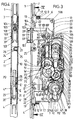
- the espagnolette lock has a lock housing 2 connected to a cuff 1.
- the cuff 1 fastened to one narrow side of the lock housing 2 has a greater length than the lock housing 2 and extends over an upper and a lower drive rod 3 or, respectively, emerging from the lock housing 2. 4.
- the latter are provided with locking members 5 which cooperate with counter-closing parts, not shown, on the frame.
- bearing blocks 8 extend from the rear surface of the cuff 1 and continue to form a step in rearward-facing fastening projections 9.
- the fastening projections 9 projecting over the narrow side walls 6, 7 have a trapezoidal shape such that the base of the trapezium faces the interior of the lock housing.
- both the lock base 10 and the lock cover 11 running parallel thereto form insertion pockets 12 and 13 on the narrow side walls.
- the pocket 12 formed by the lock base 10 is obtuse-angled.
- An angular section 12 'lies on the facing side wall of the fastening projection 9, while the adjoining angular section 12' is supported flat on the trapezoidal surface opposite the base.
- the angle section 12 ' is equipped with a passage opening 14 which is aligned with a threaded bore 15 of the fastening projection 9. Otherwise, this threaded hole runs parallel to the cuff 1.
- the other insertion pocket 13 in turn also has an angular shape.
- the directly from the castle ceiling 11 angle leg 13 ' is supported on the facing oblique flank of the trapezoidal fastening projection 9.
- the adjoining angle leg 13 ⁇ extends over the angle leg 12 ⁇ and lies flat on this.
- There the angle leg 13 ⁇ is equipped with a hole 16.
- the outer surface 18 of the bearing blocks 8 is convexly curved.
- the outer surface of the fastening projections 9 and the insertion pockets 12, 13 formed by angled portions also extend within this convex curvature, cf. 5 and 6. This makes it possible to produce pockets on the doors that are adapted to the shape of the lock housing at the height of the bearing blocks 8.
- Each bearing block 8 has a projection 19 with an oval cross section for fixing it on the cuff 1, which is inserted into a shape-adapted recess 20 of the cuff and riveted there, cf. 5 and 7 in particular.
- the bearing blocks 8 form centering brackets 22, which are immersed in shape-matched edge recesses in the lock base 10 and lock cover 11.
- the aforementioned centering tabs 22 are flush with the outer surfaces of the lock base 10 and lock cover 11.
- the lower drive rod 4 is forked in the region of the section crossing the bearing block 8.
- a longitudinal slot 29 is formed by the two fork tines 4 ', 4 ⁇ .
- Each fork 4 '. 4 ⁇ is provided with an angled end portion E, E ', which rest on the lock base 10 and immerse in shape-matched coupling recesses 31, 32 of a drive rod connecting slide 28 lying flat on the lock base 10.
- the aforementioned longitudinal slot 29 extends at the level of a through hole 30 of the cuff 1 for a lock cylinder fastening screw 30 '.
Landscapes
- Engineering & Computer Science (AREA)
- Mechanical Engineering (AREA)
- Lock And Its Accessories (AREA)
- Saccharide Compounds (AREA)
- Polysaccharides And Polysaccharide Derivatives (AREA)
- Prostheses (AREA)
- Soil Working Implements (AREA)
- Harvester Elements (AREA)
- Clamps And Clips (AREA)
Claims (8)
- Serrure, en particulier serrure à barres mobiles, avec un recouvrement (1) fixé sur un premier côté étroit du boîtier de serrure (2), caractérisée en ce que le recouvrement (1) est équipé sur son flan arrière de saillies de fixation (9), se projetant sur les deuxième côtés étroits (6, 7) du boîtier de serrure (2), s'étendant perpendiculairement aux premier côtés étroits.
- Serrure, en particulier serrure à barres mobiles, avec un recouvrement (1) fixé sur le premier côté étroit du boîtier (2), caractérisée en ce que les parois s'étendant perpendiculairement aux premiers côtés étroits, des côtés étroits (6, 7) sont dotés de poches d'enfichage (12, 13) pour des saillies de fixation (9) prévues sur le recouvrement.
- Serrure selon la revendication 1 ou 2, caractérisée en ce que les saillies de fixation (9) sont maintenues sur les parois des petits côtés (6, 7) au moyen de boulons (17) orientés parallèlement au recouvrement (1).
- Serrure selon l'une des revendications précédentes, caractérisée en ce que les poches d'enfichage (12, 13) sont formées par des rabattements du palastre (10) et du couvercle de serrure (11).
- Serrure, en particulier serrure à barres mobiles, selon l'une des revendications précédentes, caractérisée en ce que les saillies de fixation (9) partent de petits blocs de montage (8) destinés auxdites barres mobiles (3, 4) les traversants.
- Serrure, en particulier serrure à barres mobiles, selon l'une des revendications précédentes, caractérisée en ce que la surface extérieure (18) des saillies de fixation/poche/petits blocs de montage présente une courbure convexe.
- Serrure, en particulier serrure à barres mobiles, selon l'une des revendications précédentes, caractérisée en ce qu'une première barre mobile (4) est fourchue dans la zone de son tronçon croisant le petit bloc de montage (8) et les deux dents de fourche (4′, 4˝) sont situées chacune en contact d'ajustement de forme séparées par rapport à un curseur de raccordement de barres mobiles (28).
- Serrure selon l'une des revendications précédentes, caractérisée par au moins un point de fixation supplémentaire entre recouvrement (1) et palastre (10), par l'intermédiaire duquel un boulon (26), traversant le palastre (10), vient au contact de la saillie (24) se projetant en face arrière du recouvrement (1).
Priority Applications (1)
| Application Number | Priority Date | Filing Date | Title |
|---|---|---|---|
| EP93114824A EP0581326B1 (fr) | 1990-05-02 | 1991-02-25 | Serrure crémone |
Applications Claiming Priority (2)
| Application Number | Priority Date | Filing Date | Title |
|---|---|---|---|
| DE4014040A DE4014040A1 (de) | 1990-05-02 | 1990-05-02 | Schloss, insbesondere treibstangenschloss |
| DE4014040 | 1990-05-02 |
Related Child Applications (2)
| Application Number | Title | Priority Date | Filing Date |
|---|---|---|---|
| EP93114824A Division EP0581326B1 (fr) | 1990-05-02 | 1991-02-25 | Serrure crémone |
| EP93114824.1 Division-Into | 1993-09-15 |
Publications (2)
| Publication Number | Publication Date |
|---|---|
| EP0454958A1 EP0454958A1 (fr) | 1991-11-06 |
| EP0454958B1 true EP0454958B1 (fr) | 1994-06-22 |
Family
ID=6405552
Family Applications (2)
| Application Number | Title | Priority Date | Filing Date |
|---|---|---|---|
| EP93114824A Expired - Lifetime EP0581326B1 (fr) | 1990-05-02 | 1991-02-25 | Serrure crémone |
| EP91102726A Expired - Lifetime EP0454958B1 (fr) | 1990-05-02 | 1991-02-25 | Serrure, notamment serrure avec bielle motrice |
Family Applications Before (1)
| Application Number | Title | Priority Date | Filing Date |
|---|---|---|---|
| EP93114824A Expired - Lifetime EP0581326B1 (fr) | 1990-05-02 | 1991-02-25 | Serrure crémone |
Country Status (3)
| Country | Link |
|---|---|
| EP (2) | EP0581326B1 (fr) |
| AT (2) | ATE180539T1 (fr) |
| DE (3) | DE4014040A1 (fr) |
Families Citing this family (7)
| Publication number | Priority date | Publication date | Assignee | Title |
|---|---|---|---|---|
| DE9208526U1 (de) * | 1992-06-25 | 1992-09-10 | Gretsch-Unitas GmbH Baubeschläge, 7257 Ditzingen | Schloß, insbesondere Einsteckschloß für eine Außentür |
| HU214809B (hu) * | 1993-11-22 | 1998-05-28 | János Fehérdi | Zárszerkezet |
| EP1887044A4 (fr) | 2005-05-12 | 2009-05-27 | Mitsui Chemicals Inc | Composition polymere d'acide lactique, article moule fabrique a partir de ladite composition et procede de production d'un tel article moule |
| AT513464B1 (de) * | 2012-09-06 | 2015-01-15 | Roto Frank Ag | Mehrfachverriegelungsschloss |
| AT14921U1 (de) * | 2015-02-19 | 2016-08-15 | Roto Frank Ag | Schloss |
| US12180745B2 (en) | 2020-07-01 | 2024-12-31 | Cmech (Guangzhou) Ltd. | Door lock with handle |
| US12523061B2 (en) | 2020-07-01 | 2026-01-13 | Cmech (Guangzhou) Ltd. | Door lock with handle |
Family Cites Families (8)
| Publication number | Priority date | Publication date | Assignee | Title |
|---|---|---|---|---|
| US4237711A (en) * | 1978-02-10 | 1980-12-09 | Brink's Locking Systems, Inc. | Lock mechanism |
| JPS5833348B2 (ja) * | 1979-08-23 | 1983-07-19 | 基博 五反田 | 錠装置 |
| FR2488318B1 (fr) * | 1980-08-08 | 1985-07-26 | Chauvat Sofranq | Serrure a larder du type trois points |
| AT366750B (de) * | 1980-11-13 | 1982-05-10 | Grundmann Rohrbacher Schlosser | Tuerverschluss |
| DE3142959C2 (de) * | 1981-08-04 | 1985-06-05 | BKS Sicherheitstechnik GmbH, 5040 Brühl | Treibstangenverschluß für Türen |
| AU557075B2 (en) * | 1981-11-19 | 1986-12-04 | Lockwood Security Products Pty Limited | Screen door lock |
| GB8517168D0 (en) * | 1985-07-05 | 1985-08-14 | Gkn Crompton | Latch mechanism |
| GB8811734D0 (en) * | 1988-05-18 | 1988-06-22 | Goodwin W J & Son Ltd | Improvements in/relating to locking mechanisms |
-
1990
- 1990-05-02 DE DE4014040A patent/DE4014040A1/de not_active Withdrawn
-
1991
- 1991-02-25 DE DE59101979T patent/DE59101979D1/de not_active Expired - Fee Related
- 1991-02-25 EP EP93114824A patent/EP0581326B1/fr not_active Expired - Lifetime
- 1991-02-25 DE DE59109131T patent/DE59109131D1/de not_active Expired - Fee Related
- 1991-02-25 AT AT93114824T patent/ATE180539T1/de not_active IP Right Cessation
- 1991-02-25 AT AT91102726T patent/ATE107732T1/de not_active IP Right Cessation
- 1991-02-25 EP EP91102726A patent/EP0454958B1/fr not_active Expired - Lifetime
Also Published As
| Publication number | Publication date |
|---|---|
| EP0454958A1 (fr) | 1991-11-06 |
| EP0581326B1 (fr) | 1999-05-26 |
| EP0581326A1 (fr) | 1994-02-02 |
| ATE107732T1 (de) | 1994-07-15 |
| DE4014040A1 (de) | 1991-11-07 |
| DE59101979D1 (de) | 1994-07-28 |
| DE59109131D1 (de) | 1999-07-01 |
| ATE180539T1 (de) | 1999-06-15 |
Similar Documents
| Publication | Publication Date | Title |
|---|---|---|
| EP0384224B1 (fr) | Dispositif de guidage | |
| EP0513031A1 (fr) | Serrure a fonction de fermeture deblocable par insertion d'une carte codee magnetisee par zones. | |
| DE3645256C2 (de) | Fenster- und Türbeschlag | |
| DE4014041A1 (de) | Schliesszylinderbetaetigbares treibstangenschloss | |
| EP1209305A1 (fr) | Système d'éléments de construction pour l'assemblage de serrures cylindriques | |
| EP0581326B1 (fr) | Serrure crémone | |
| DE3111247A1 (de) | Einsteckschloss | |
| EP2735675B1 (fr) | Dispositif de fermeture pour portes doté d'une plaque de porte asymétrique | |
| WO1994010415A1 (fr) | Fermeture a tourniquet | |
| EP0454959B1 (fr) | Serrure de barre coulissante manoeuvrable d'un barillet | |
| EP0454965B1 (fr) | Serrure encatrée notamment avec bielle motrice | |
| EP0454960B1 (fr) | Cremone | |
| DE3600435C2 (fr) | ||
| DE10100763B4 (de) | Einsteckschloss mit Kunststoffriegel | |
| AT402651B (de) | Getriebe für einen riegelstangenbeschlag einer getriebe für einen riegelstangenbeschlag einer tür oder eines fensters tür oder eines fensters | |
| DE2804603C2 (de) | Riegelblockiervorrichtung in einem Schloß mit schlüsselbetätigbarer Zuhaltung | |
| DE2327086A1 (de) | Stulpschienen-eckverbindung, insbesondere an treibstangenbeschlaegen | |
| EP0163816B1 (fr) | Dispositif de liaison pour tiges de commande, en particulier pour des ferrures oscillo-battantes pour fenêtres, portes ou similaires | |
| DE2435847B1 (de) | Kupplungseinrichtung in einem unsymmetrischen doppelzylinderschloss | |
| DE4302920C2 (de) | Schloß, insbesondere Einsteckschloß | |
| DE9007786U1 (de) | Schließzylinderbetätigbares Treibstangenschloß | |
| DE8426131U1 (de) | Profilrahmen fuer ein fenster, eine tuer od. dgl. mit einem getriebegriff od. dgl. | |
| DE2617392A1 (de) | Drehstangenschloss | |
| DE3346711A1 (de) | Moebelscharnier fuer tueren, klappen o.dgl. | |
| EP0198441A2 (fr) | Pièce d'assemblage pour profilés creux se raccordant sous un angle |
Legal Events
| Date | Code | Title | Description |
|---|---|---|---|
| PUAI | Public reference made under article 153(3) epc to a published international application that has entered the european phase |
Free format text: ORIGINAL CODE: 0009012 |
|
| AK | Designated contracting states |
Kind code of ref document: A1 Designated state(s): AT DE FR GB IT |
|
| 17P | Request for examination filed |
Effective date: 19910919 |
|
| 17Q | First examination report despatched |
Effective date: 19930824 |
|
| GRAA | (expected) grant |
Free format text: ORIGINAL CODE: 0009210 |
|
| AK | Designated contracting states |
Kind code of ref document: B1 Designated state(s): AT DE FR GB IT |
|
| REF | Corresponds to: |
Ref document number: 107732 Country of ref document: AT Date of ref document: 19940715 Kind code of ref document: T |
|
| GBT | Gb: translation of ep patent filed (gb section 77(6)(a)/1977) |
Effective date: 19940622 |
|
| REF | Corresponds to: |
Ref document number: 59101979 Country of ref document: DE Date of ref document: 19940728 |
|
| ET | Fr: translation filed | ||
| ITF | It: translation for a ep patent filed | ||
| PLBE | No opposition filed within time limit |
Free format text: ORIGINAL CODE: 0009261 |
|
| STAA | Information on the status of an ep patent application or granted ep patent |
Free format text: STATUS: NO OPPOSITION FILED WITHIN TIME LIMIT |
|
| 26N | No opposition filed | ||
| REG | Reference to a national code |
Ref country code: GB Ref legal event code: IF02 |
|
| PGFP | Annual fee paid to national office [announced via postgrant information from national office to epo] |
Ref country code: AT Payment date: 20061222 Year of fee payment: 17 Ref country code: DE Payment date: 20061222 Year of fee payment: 17 |
|
| PGFP | Annual fee paid to national office [announced via postgrant information from national office to epo] |
Ref country code: GB Payment date: 20061228 Year of fee payment: 17 |
|
| PGFP | Annual fee paid to national office [announced via postgrant information from national office to epo] |
Ref country code: IT Payment date: 20070612 Year of fee payment: 17 |
|
| PGFP | Annual fee paid to national office [announced via postgrant information from national office to epo] |
Ref country code: FR Payment date: 20061220 Year of fee payment: 17 |
|
| GBPC | Gb: european patent ceased through non-payment of renewal fee |
Effective date: 20080225 |
|
| PG25 | Lapsed in a contracting state [announced via postgrant information from national office to epo] |
Ref country code: AT Free format text: LAPSE BECAUSE OF NON-PAYMENT OF DUE FEES Effective date: 20080225 |
|
| REG | Reference to a national code |
Ref country code: FR Ref legal event code: ST Effective date: 20081031 |
|
| PG25 | Lapsed in a contracting state [announced via postgrant information from national office to epo] |
Ref country code: DE Free format text: LAPSE BECAUSE OF NON-PAYMENT OF DUE FEES Effective date: 20080902 |
|
| PG25 | Lapsed in a contracting state [announced via postgrant information from national office to epo] |
Ref country code: FR Free format text: LAPSE BECAUSE OF NON-PAYMENT OF DUE FEES Effective date: 20080229 |
|
| PG25 | Lapsed in a contracting state [announced via postgrant information from national office to epo] |
Ref country code: GB Free format text: LAPSE BECAUSE OF NON-PAYMENT OF DUE FEES Effective date: 20080225 |
|
| PG25 | Lapsed in a contracting state [announced via postgrant information from national office to epo] |
Ref country code: IT Free format text: LAPSE BECAUSE OF NON-PAYMENT OF DUE FEES Effective date: 20080225 |