EP0454973B1 - Saugkastenvorrichtung mit Verbunddeckelelementen eingesetzt in Schlitze auf Querträgern - Google Patents
Saugkastenvorrichtung mit Verbunddeckelelementen eingesetzt in Schlitze auf Querträgern Download PDFInfo
- Publication number
- EP0454973B1 EP0454973B1 EP91103732A EP91103732A EP0454973B1 EP 0454973 B1 EP0454973 B1 EP 0454973B1 EP 91103732 A EP91103732 A EP 91103732A EP 91103732 A EP91103732 A EP 91103732A EP 0454973 B1 EP0454973 B1 EP 0454973B1
- Authority
- EP
- European Patent Office
- Prior art keywords
- support members
- suction box
- conveyor belt
- papermaking machine
- braces
- Prior art date
- Legal status (The legal status is an assumption and is not a legal conclusion. Google has not performed a legal analysis and makes no representation as to the accuracy of the status listed.)
- Expired - Lifetime
Links
- 239000002131 composite material Substances 0.000 title abstract description 6
- 239000000919 ceramic Substances 0.000 claims abstract description 18
- 229910052751 metal Inorganic materials 0.000 claims abstract description 15
- 239000002184 metal Substances 0.000 claims abstract description 15
- 229920002430 Fibre-reinforced plastic Polymers 0.000 claims abstract description 7
- 239000011151 fibre-reinforced plastic Substances 0.000 claims abstract description 7
- 238000003780 insertion Methods 0.000 claims abstract description 5
- 230000037431 insertion Effects 0.000 claims abstract description 5
- 229910010293 ceramic material Inorganic materials 0.000 claims description 9
- 239000000463 material Substances 0.000 claims description 9
- XLYOFNOQVPJJNP-UHFFFAOYSA-N water Substances O XLYOFNOQVPJJNP-UHFFFAOYSA-N 0.000 claims description 9
- 239000004033 plastic Substances 0.000 claims description 5
- 229920003023 plastic Polymers 0.000 claims description 5
- 238000004026 adhesive bonding Methods 0.000 claims description 2
- 239000011152 fibreglass Substances 0.000 claims description 2
- 238000003466 welding Methods 0.000 abstract description 5
- 238000010276 construction Methods 0.000 description 2
- 239000003822 epoxy resin Substances 0.000 description 2
- 239000004744 fabric Substances 0.000 description 2
- 238000004519 manufacturing process Methods 0.000 description 2
- 229920000647 polyepoxide Polymers 0.000 description 2
- 239000004698 Polyethylene Substances 0.000 description 1
- 238000005266 casting Methods 0.000 description 1
- 239000011888 foil Substances 0.000 description 1
- 238000009434 installation Methods 0.000 description 1
- 239000002650 laminated plastic Substances 0.000 description 1
- 238000003754 machining Methods 0.000 description 1
- 238000012423 maintenance Methods 0.000 description 1
- 230000013011 mating Effects 0.000 description 1
- QSHDDOUJBYECFT-UHFFFAOYSA-N mercury Chemical compound [Hg] QSHDDOUJBYECFT-UHFFFAOYSA-N 0.000 description 1
- 229910052753 mercury Inorganic materials 0.000 description 1
- 238000000034 method Methods 0.000 description 1
- 230000009972 noncorrosive effect Effects 0.000 description 1
- 239000004745 nonwoven fabric Substances 0.000 description 1
- 239000011224 oxide ceramic Substances 0.000 description 1
- TWNQGVIAIRXVLR-UHFFFAOYSA-N oxo(oxoalumanyloxy)alumane Chemical compound O=[Al]O[Al]=O TWNQGVIAIRXVLR-UHFFFAOYSA-N 0.000 description 1
- RVTZCBVAJQQJTK-UHFFFAOYSA-N oxygen(2-);zirconium(4+) Chemical compound [O-2].[O-2].[Zr+4] RVTZCBVAJQQJTK-UHFFFAOYSA-N 0.000 description 1
- 229920000728 polyester Polymers 0.000 description 1
- -1 polyethylene Polymers 0.000 description 1
- 229920000573 polyethylene Polymers 0.000 description 1
- 239000003566 sealing material Substances 0.000 description 1
- 229910001220 stainless steel Inorganic materials 0.000 description 1
- 239000010935 stainless steel Substances 0.000 description 1
- 239000002023 wood Substances 0.000 description 1
- 229910001928 zirconium oxide Inorganic materials 0.000 description 1
Images

Classifications
-
- D—TEXTILES; PAPER
- D21—PAPER-MAKING; PRODUCTION OF CELLULOSE
- D21F—PAPER-MAKING MACHINES; METHODS OF PRODUCING PAPER THEREON
- D21F1/00—Wet end of machines for making continuous webs of paper
- D21F1/48—Suction apparatus
- D21F1/52—Suction boxes without rolls
-
- D—TEXTILES; PAPER
- D21—PAPER-MAKING; PRODUCTION OF CELLULOSE
- D21F—PAPER-MAKING MACHINES; METHODS OF PRODUCING PAPER THEREON
- D21F1/00—Wet end of machines for making continuous webs of paper
- D21F1/48—Suction apparatus
- D21F1/52—Suction boxes without rolls
- D21F1/523—Covers thereof
Definitions
- the subject matter of the present invention relates generally to dewatering apparatus for papermaking machines and in particular to suction box apparatus, including a composite suction box cover having cover elements mounted in slots on cross braces.
- the cross braces which may be of metal extend across such cover elements and longitudinally of the porous conveyor belt conveying the paper web from which water is to be removed by the suction box or other dewatering apparatus.
- the composite suction box cover is preferably formed by cover strips of ceramic material bonded to fiber-reinforced plastic support members extending beneath such ceramic strips.
- the support members are provided with mounting projections which engage mounting slots in the cross braces for releasably mounting such cover strips on such cross braces without the use of threaded fasteners such as screws or bolts and without the need for welding or other time-consuming and expensive fastening means.
- the drainage apparatus of the present invention is especially useful in the manufacture of paper, pulp stock and nonwoven fabrics for the removal of water from the material being manufactured.
- a suction box cover apparatus embodying the present invention avoids the need for welding or threaded fasteners by using metal cross braces which are slotted with mounting slots to engage mounting projections on the bottom of support members of fiber-reinforced plastic material to which the cover strips of ceramic material are bonded. This overcomes the above-mentioned problems and has the added advantage that allows the cover elements to be easily inserted and removed in the case of damage or replacement of the cover elements for other reasons.
- the cross braces are made in a simple and inexpensive manner by machining metal bar stock rather than requiring the bracing to be made by casting, and thereby allows a greater flexibility in the design of the suction box cover to accommodate changes in the width of the cover elements and the drainage slot spacing between elements which varies, depending upon many factors, including the position of the suction box in the papermaking machine and the vacuum pressure within such suction box.
- DE 3823882 discloses a suction box having cross braces to which are fixedly attached, by bonding with epoxy resin bonding material, rectangular cross-section support members.
- this extremely complicated device differs from that of the present invention in that it employs bolts to fasten the T-bar brackets which can loosen and fall out to damage the conveyor wire and does not provide slotted cross braces having mounting slots in which the cover elements are secured by mounting projections on the bottom of such cover elements.
- Suction box covers have previously been provided with metal cross braces as shown in U.S. Patent No. 1,657,509 of Latham, issued January 31, 1928, and U.S. Patent No. 1,696,917 of Lewis, issued January 1, 1929;, which show cover elements of wood attached to metal bars supported on cross braces or bridge members.
- U.S. Patent No. 3,708,390 of Krake, issued January 2, 1973 discloses a felt dewatering apparatus, including a suction box employing plastic cover elements attached to J-shaped metal supports supported on a metal plate.
- metal cross braces have not been employed to mount suction box cover elements directly thereon by means of mounting slots provided in such cross braces in the manner of the present invention.
- the invention provides a papermaking machine having a paper-forming section including a suction box apparatus which comprises:
- the present invention enables the provision of an improved suction box of simple and economical construction.
- cover strips of ceramic material may be attached to support members of fiber-reinforced plastic material provided with mounting projections on the bottom thereof for insertion in the mounting slots provided on the cross braces in order to provide a suction box cover which is lightweight and of great strength so it can span a wider paper sheet and operate at a higher vacuum pressure while also being highly wear-resistant.
- Embodiments of the invention provide a papermaking machine having a suction box apparatus of simple and inexpensive construction, employing slotted cross braces with mounting slots therein for mounting the suction box cover elements thereon without employing bolts, screws or other mechanical fasteners or welding, thereby reducing the danger of damage to the porous conveyor belt by falling fasteners, which is less costly to manufacture and is more versatile apparatus whose cover elements and drainage slots can be changed in width to accommodate different dewatering conditions.
- the slotted cross braces may be provided with mounting slots of dovetail or T-shape that hold the cover elements in a fixed position to prevent vertical movement toward or way from the conveyor belt but which allow sliding movement horizontally for insertion and removal of the cover elements in the mounting slots.
- the cross braces may be provided with tapered top portions facing the conveyor belt to improve the water flow during dewatering.
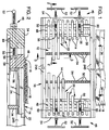
- one embodiment of the drainage apparatus of the present invention is a suction box apparatus 10, including a suction box connected to an external source of vacuum pressure (not shown) in a conventional manner and a suction box cover 12.
- the suction box cover is formed by spaced cover elements 14 which may be composite structures extending across the width of a porous conveyor belt 16.
- the conveyor belt may be metal wire or woven plastic fabric and is motor driven at high speed up to 1067 metres per minute (3,500 feet per minute) to convey a paper web 18 across such suction box cover for removing water from such paper web.
- the suction box cover elements 14 are spaced apart by drainage slots 20 which extend across the width of the conveyor belt 16 to allow water which is drawn from the paper web 18 through the conveyor belt 16 by the vacuum pressure within the suction box to drain through slots 20 into the suction box.
- the suction box has an external vacuum pressure source connected thereto, which reduces the pressure within the suction box below atmospheric pressure of, for example, about 33.86 to 67.72 kPa (10 to 20 inches of mercury pressure).
- the suction box cover elements 14 may be composite structures formed by cover strips 22 of ceramic material such as aluminum oxide or zirconium oxide ceramic, which extend across the full width of the paper web 18 and whose upper surface contacts conveyor belt 16.
- the ceramic cover strips 22 are fixed to support members 24 of fiber-reinforced plastic material such as fiberglass-reinforced polyester.
- the ceramic cover strips 22 are each formed of a plurality of segments mounted end to end and provided with a tongue portion 26 which extends downwardly away from the conveyor belt 16 into a mating groove 28 in the top of the support member 24.
- Adhesive bonding material such as epoxy resin is provided at the interface between the tongue projection 26 and the groove 28 in order to bond the ceramic strips 22 to the fiberglass-reinforced plastic support members 24.
- the central support members 24 between the two outer support members 24A and 24B are each provided with a mounting projection 30 on the bottom thereof which is of a configuration to mate with mounting slots 32 provided in metal cross braces 34.
- the cross braces extend across the suction box cover 12 in a direction longitudinally of the conveyor belt 16 which in Fig. 3 moves in a direction right to left indicated by arrow 36.
- the mounting slots 32 in the cross braces 34 have a dovetail shape and mate with dovetail projections 30 at the bottom of the supporting members 24.
- a plurality of spaced cross braces 34 are provided beneath the cover elements 14, each of such cross braces being provided with a number of mounting slots 32 which correspond to the number of cover elements 14.
- the opposite ends of the cross braces 34 are fastened to the outer support members 24A and 24B of the suction box cover, respectively positioned at the trailing and leading ends of the suction box by means of bolts 38 as shown in Fig. 3.
- the bolts 38 are screwed into threaded holes in the opposite ends of each of the metal cross braces 34 to attach such cross braces so that they each extend across all of the suction box cover elements 14 to support such elements in mounting slots 32 and extend longitudinally of the conveyor belt 16 as shown in Fig. 1.
- the cross braces 34 are made of stainless steel or other noncorrosive metal and are provided with tapered top portions 40 between each of the mounting slots 32.
- the tapered top portion 40 tapers from a maximum width at a mid-portion of the cross brace to a pointed ridge 42 at the top of such cross brace, as shown in Fig. 4.
- This tapered top portion increases the water drainage efficiency through such cross braces for water which is removed from the paper web 18 and passes through the porous conveyor belt 16 into the suction box as a result of the vacuum pressure within the suction box.
- the slope of the sides of the top portion 40 are approximately 30° with respect to the vertical projection of the sides of such cross brace. As shown in Fig.
- the suction box cover elements 14 are inserted into and removed from the mounting slots 32 in the cross brace 34 by horizontal sliding movement in the direction of arrow 44 to enable installation or removal of a cover element without the need to remove the conveyor belt from the papermaking machine which would otherwise require stopping the machine. This enables replacement of damaged or worn cover elements or the replacement of cover elements of different size in a simple and inexpensive manner without the need to shut down the papermaking machine.
- an adjustable deckle device 46 may be provided on the opposite sides of the suction box cover 12 to allow paper webs of different width to be formed thereon.
- the deckle device includes a deckle seal member 48 of a suitable sealing material such as polyethylene plastic which is notched to fit between the suction box cover elements 14 in order to fill the drainage slots and seal the space between such elements at the end of such slots to provide a vacuum seal with the opposite edges of the paper web 18 as they pass over such deckle members.
- the deckle members 48 are adjusted in position laterally across the conveyor belt 16 to accommodate paper webs of different width by means of adjustment screws 50 having handles 52 attached to the outer ends of the screw shafts.
- the adjustment screw shafts pass through drilled passages in two plastic laminate end members 54 and are secured to the deckle seal member 48 by locknuts 56 on the opposite sides of such seal members, as shown in Fig. 2.
- rotation of the handles 52 causes rotation of the adjustment screw shafts 50 which slides the deckle seal members 48 toward and away from the end member 54 in order to adjust the lateral position of the deckle members.
- the deckle member 48 slides across a support plate 58 of metal which is fastened by bolts 60 to the bottom of the end member 54 and forms a vacuum seal with such support plate to prevent pressure leaks between the deckle member 48 and the end member 54.
- the present invention having a suction box cover with an overall length across the conveyor belt of about 7.11 m (280"), twenty-nine of the cross braces 34, each 38.1 mm (1.5") high, 19.05 mm (0.5") wide and 342.9 mm (13.5") long, were provided, equally spaced 203.2 mm (8") apart, with the space between the two deckle members 48 varying between about 6121.4 mm (241") and 6.2484 m (246").
- the ceramic cover strips 22 were about 15.88 mm (0.625") wide, 11.1 mm (0.437”) high and 6.391 m (251.63") long while the drainage slots 20 between such strips were approximately 19.05 mm (0.750”) wide.
- suction box cover elements 14 were employed in this cover so that the width of the suction box from the front end support member 24B to the rear end support member 24A was about 371.5 mm (14.625") at the top of the suction box, such end support members being clamped to the body of the suction box in a conventional manner by means of mechanical clamps not shown.
- the width of the suction box cover elements and the drainage slot spacing between such elements can vary, depending upon the position of the suction box within the papermaking machine and the operating conditions.
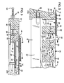
- FIG. 5 and 6 A second embodiment of the suction box apparatus of the present invention is shown in Figs. 5 and 6 which is similar to the embodiment of Figs. 1 and 4 so that the same reference numbers are used to designate similar parts and only the differences will be described and shown.
- T-shaped mounting slots 62 are provided in the cross braces 34 which are of an inverted T-shaped cross section.
- a mounting projection 64 of a corresponding T-shaped cross section is provided on the bottom of each of the support members 24' which are bonded to the ceramic cover strips 22 forming the cover elements 14'.
- the embodiment of Figs. 5 and 6 differs only in the shape of the mounting slots 62 in the cross braces 34 and the shape of the mounting projections 64 on the bottom of the support members 24 for the ceramic strips 22.
Landscapes
- Paper (AREA)
- Bending Of Plates, Rods, And Pipes (AREA)
- Bridges Or Land Bridges (AREA)
Claims (10)
- Maschine zur Papierherstellung mit einem Abschnitt zum Formen des Papiers, der eine Saugkastenvorrichtung beinhaltet, welche umfaßt:einen Saugkasten (10) zum Entfernen von Wasser von einer Papierbahn (18), die mittels eines porösen Förderbandes (16) über den Saugkasten (10) transportiert wird;eine Saugkastenabdeckung (12), die eine Vielzahl von Abdeckstreifen (22) aus keramischem Material beinhaltet, die sich über die Breite des Förderbandes (16) erstrecken und auf dem Saugkasten (10) mit gegenseitigem Abstand entlang der Länge des Förderbandes (16) abgestützt sind, so daß das Förderband (16) die keramischen Abdeckstreifen (22) erfaßt und die Abdeckstreifen (22) durch Entwässerungsschlitze (20) voneinander getrennt sind; undeine Abstützeinrichtung zum Abstützen der keramischen Abdeckstreifen (22), wobei die Abstützeinrichtung Abstützteile (24) aus nicht-keramischem Material beinhaltet, die an den Abdeckstreifen (22) befestigt sind und sich längs der Abdeckstreifen (22) quer über die Breite des Förderbandes (16) erstrecken, wobei die Abstützeinrichtung weiter eine Anzahl von Querträgern (34) beinhaltet, die mit einem gegenseitigen seitlichen Abstand quer zum Förderband (16) angeordnet sind und sich in Längsrichtung des Förderbands (16) quer über die Abstützteile (24) erstrecken; gekennzeichnet durch Befestigungsschlitze (32) in den Querträgern (34), die Befestigungsvorsprünge (30) auf den Abstützteilen (24) verschieblich aufnehmen, um lösbar ineinandergreifende Verbindungen zwischen den Abstützteilen (24) und den Querträgern (34) zu bilden, wobei die ineinandergreifenden Verbindungen eine seitliche Bewegung der Abstützteile (24) innerhalb der Befestigungsschlitze verhindern und eine Bewegung der Abstützteile (24) in Richtung auf das Förderband (16) oder davon weg verhindern, während sie eine verschiebliche Bewegung der Abstützteile (24) relativ zu den Querträgern (34) zum Einfügen der Befestigungsvorsprünge (30) in die Befestigungsschlitze (32) oder zum Herausnehmen der Befestigungsvorsprünge daraus zulassen.
- Papiermaschine nach Anspruch 1, dadurch gekennzeichnet, daß die Abstützteile (24) aus faserverstärktem Kunststoffmaterial und die Querträger (34) aus Metall bestehen.
- Papiermaschine nach Anspruch 1 oder 2, dadurch gekennzeichnet, daß die Abstützteile (24) Glasfasern enthalten.
- Papiermaschine nach einem der vorangehenden Ansprüche, dadurch gekennzeichnet, daß die Befestigungsschlitze (32) und Vorsprünge (30) schwalbenschwanzförmig ausgebildet sind.
- Papiermaschine nach einem der Ansprüche 1 bis 3, dadurch gekennzeichnet, daß die Befestigungsschlitze (32) und Vorsprünge (30) T-förmig sind.
- Papiermaschine nach einem der vorangehenden Ansprüche, dadurch gekennzeichnet, daß die Querträger (34) Zwischenabschnitte (40) zwischen den Befestigungsschlitzen (32) aufweisen, die an ihren äußeren, sich in Richtung auf das Förderband (16) erstreckenden Kanten sich verjüngend zu gratartigen Erhebungen (42) zulaufen.
- Papiermaschine nach einem der vorangehenden Ansprüche, dadurch gekennzeichnet, daß die keramischen Abdeckstreifen (22) zungenartige Abschnitte (26) beinhalten, die sich in Nuten (28) in den Abstützteilen (24) erstrecken und mit diesen fest verbunden sind.
- Papiermaschine nach Anspruch 7, dadurch gekennzeichnet, daß die feste Verbindung durch ein festhaftendes Klebematerial in den Nuten (28) geschaffen wird.
- Papiermaschine nach einem der vorangehenden Ansprüche, dadurch gekennzeichnet, daß die Querträger (34) mittels Schraubbefestigungen (38) an vorderen und hinteren Trägern (24A, B) gehalten sind, die sich in Querrichtung über den Förderer erstrecken.
- Papiermaschine nach Anspruch 9, dadurch gekennzeichnet, daß die vorderen und hinteren Träger (24A, B) Abstützteile (24) aus Kunststoff für die vorderen und hinteren keramischen Abdeckstreifen (22) an den vorderen und hinteren Kanten des Saugkastens (10) sind.
Applications Claiming Priority (2)
| Application Number | Priority Date | Filing Date | Title |
|---|---|---|---|
| US52036990A | 1990-05-04 | 1990-05-04 | |
| US520369 | 1995-08-28 |
Publications (2)
| Publication Number | Publication Date |
|---|---|
| EP0454973A1 EP0454973A1 (de) | 1991-11-06 |
| EP0454973B1 true EP0454973B1 (de) | 1996-05-08 |
Family
ID=24072305
Family Applications (1)
| Application Number | Title | Priority Date | Filing Date |
|---|---|---|---|
| EP91103732A Expired - Lifetime EP0454973B1 (de) | 1990-05-04 | 1991-03-12 | Saugkastenvorrichtung mit Verbunddeckelelementen eingesetzt in Schlitze auf Querträgern |
Country Status (5)
| Country | Link |
|---|---|
| EP (1) | EP0454973B1 (de) |
| JP (1) | JP3065120B2 (de) |
| AT (1) | ATE137826T1 (de) |
| CA (1) | CA2036540C (de) |
| DE (1) | DE69119295T2 (de) |
Cited By (1)
| Publication number | Priority date | Publication date | Assignee | Title |
|---|---|---|---|---|
| DE102013002122A1 (de) * | 2013-02-08 | 2014-08-14 | Jörg Scheffler | Transportvorrichtung für Papier und Papierbearbeitungseinrichtung |
Families Citing this family (6)
| Publication number | Priority date | Publication date | Assignee | Title |
|---|---|---|---|---|
| US5630910A (en) * | 1995-06-26 | 1997-05-20 | Jwi Ltd. | Clip fastener for a dewatering box |
| AT412657B (de) * | 2002-10-17 | 2005-05-25 | Bartelmuss Klaus Ing | Vorrichtung für eine mindestens ein siebband aufweisende anlage zur papiererzeugung |
| AT500751B8 (de) * | 2003-02-20 | 2007-02-15 | Bartelmuss Klaus Ing | Vorrichtung zur behandlung, insbesondere zur unterdruck-beaufschlagung, des in einer anlage zur papiererzeugung vorgesehenen, im umlauf bewegten mindestens einen siebbandes bzw. filzbandes |
| AT413392B (de) * | 2003-05-28 | 2006-02-15 | Bartelmuss Klaus Ing | Abstütz- bzw. abstreifeinrichtung für siebbandanlagen |
| CA2546273C (en) | 2003-11-17 | 2011-02-22 | Astenjohnson, Inc. | Shaped slot vacuum dewatering box cover |
| AT524317B1 (de) | 2021-06-08 | 2022-05-15 | Bartelmuss Ing Klaus | Abstreifleiste und Bausatz zur Verwendung in einer Anlage zur Erzeugung einer Papierbahn |
Family Cites Families (8)
| Publication number | Priority date | Publication date | Assignee | Title |
|---|---|---|---|---|
| US1657509A (en) * | 1925-09-16 | 1928-01-31 | Oxford Paper Co | Suction box for paper-making machines |
| US1696917A (en) * | 1926-05-20 | 1929-01-01 | Lewis Archelaus | Suction-box cover |
| AT280035B (de) * | 1964-02-07 | 1970-03-25 | Feldmuehle Ag | Entwässerungsleiste für Papiermaschinen |
| US3708390A (en) * | 1970-09-14 | 1973-01-02 | Kimberly Clark Co | Suction box for a papermaking machine having multiple compartments formed by j-shaped elements |
| GB1559277A (en) * | 1975-11-06 | 1980-01-16 | Jwi Ltd | Stock formation in a paper making process |
| FI52131C (fi) * | 1976-02-25 | 1977-06-10 | Tampella Oy Ab | Vedenpoistolista paperi- tai kartonkikoneen viiraosaa varten. |
| US4334958A (en) * | 1980-08-25 | 1982-06-15 | Fred W. Meyers | Production of conveyor support bars for paper making machinery |
| DE3823882A1 (de) * | 1988-07-14 | 1990-01-18 | Feldmuehle Ag | Schlitzsauger |
-
1991
- 1991-02-18 CA CA002036540A patent/CA2036540C/en not_active Expired - Fee Related
- 1991-03-12 EP EP91103732A patent/EP0454973B1/de not_active Expired - Lifetime
- 1991-03-12 AT AT91103732T patent/ATE137826T1/de not_active IP Right Cessation
- 1991-03-12 DE DE69119295T patent/DE69119295T2/de not_active Expired - Fee Related
- 1991-05-01 JP JP3126559A patent/JP3065120B2/ja not_active Expired - Fee Related
Cited By (2)
| Publication number | Priority date | Publication date | Assignee | Title |
|---|---|---|---|---|
| DE102013002122A1 (de) * | 2013-02-08 | 2014-08-14 | Jörg Scheffler | Transportvorrichtung für Papier und Papierbearbeitungseinrichtung |
| US9725851B2 (en) | 2013-02-08 | 2017-08-08 | Jörg Scheffler | Transport device for paper, and paper processing device |
Also Published As
| Publication number | Publication date |
|---|---|
| EP0454973A1 (de) | 1991-11-06 |
| ATE137826T1 (de) | 1996-05-15 |
| JPH0617392A (ja) | 1994-01-25 |
| JP3065120B2 (ja) | 2000-07-12 |
| DE69119295T2 (de) | 1996-09-12 |
| CA2036540A1 (en) | 1991-11-05 |
| CA2036540C (en) | 2001-08-21 |
| DE69119295D1 (de) | 1996-06-13 |
Similar Documents
| Publication | Publication Date | Title |
|---|---|---|
| US5076894A (en) | Suction box apparatus with composite cover elements mounted in slots on cross braces | |
| EP0454973B1 (de) | Saugkastenvorrichtung mit Verbunddeckelelementen eingesetzt in Schlitze auf Querträgern | |
| US20100200187A1 (en) | Systems and methods for providing improved dewatering performance in a papermaking machine | |
| CA1045432A (en) | Stock formation in a paper making process | |
| US5034100A (en) | Stationary drainage device with pressure roll | |
| US4321108A (en) | Fourdrinier table | |
| ZA200203879B (en) | Twim fabric forming section blade mounting. | |
| EP0062983A1 (de) | Formleiste für die Siebpartie einer Papiermaschine | |
| CN1105247C (zh) | 用于输能链的导槽及其附件 | |
| EP0253508A2 (de) | Stationäre Gautschvorrichtung für Papiermaschine | |
| EP1685293B1 (de) | Vakuumentwässerungskastendeckel | |
| DE59908729D1 (de) | Drei- oder mehrlagiges Papiermaschinensieb in Form eines Verbundgewebes | |
| CA1316385C (en) | Suction box cover with modular components | |
| EP0354741A2 (de) | Vorrichtung zum Eindicken von Pulpe und Papierstoffbrei | |
| KR100337375B1 (ko) | 축장치 | |
| JP3482879B2 (ja) | サクションボックス | |
| FI109814B (fi) | Laitteisto paperi- tai kartonkirainan muodostamiseksi | |
| AU575940B2 (en) | Web forming device | |
| WO1998044193A1 (en) | Apparatus for removing fluid from a fibrous web | |
| FI79728C (fi) | Foerbaettring till anordning foer avvattning av fibroesa suspensioner. | |
| FI71791C (fi) | Arrangemang foer infaestning av foillister i pappers- eller cellulosamaskiner samt stoed- och faestbord. | |
| FI104192B (fi) | Vyöhykesäädettävä kuormituslaatikko paperi- tai kartonkikoneen formeria varten | |
| EP0000250A1 (de) | Entwässerungsleiste für eine Blattbildungsmaschine. | |
| JPH09504060A (ja) | 抄紙機のギャップフォーマ | |
| EP0852639B1 (de) | Hebeeinrichtung für die oberwalze einer presse in einer papier-oder kartonmaschine |
Legal Events
| Date | Code | Title | Description |
|---|---|---|---|
| PUAI | Public reference made under article 153(3) epc to a published international application that has entered the european phase |
Free format text: ORIGINAL CODE: 0009012 |
|
| AK | Designated contracting states |
Kind code of ref document: A1 Designated state(s): AT DE GB SE |
|
| 17P | Request for examination filed |
Effective date: 19920424 |
|
| 17Q | First examination report despatched |
Effective date: 19940421 |
|
| GRAH | Despatch of communication of intention to grant a patent |
Free format text: ORIGINAL CODE: EPIDOS IGRA |
|
| GRAA | (expected) grant |
Free format text: ORIGINAL CODE: 0009210 |
|
| AK | Designated contracting states |
Kind code of ref document: B1 Designated state(s): AT DE GB SE |
|
| REF | Corresponds to: |
Ref document number: 137826 Country of ref document: AT Date of ref document: 19960515 Kind code of ref document: T |
|
| REF | Corresponds to: |
Ref document number: 69119295 Country of ref document: DE Date of ref document: 19960613 |
|
| PLBE | No opposition filed within time limit |
Free format text: ORIGINAL CODE: 0009261 |
|
| STAA | Information on the status of an ep patent application or granted ep patent |
Free format text: STATUS: NO OPPOSITION FILED WITHIN TIME LIMIT |
|
| 26N | No opposition filed | ||
| REG | Reference to a national code |
Ref country code: GB Ref legal event code: IF02 |
|
| PGFP | Annual fee paid to national office [announced via postgrant information from national office to epo] |
Ref country code: SE Payment date: 20040304 Year of fee payment: 14 |
|
| PGFP | Annual fee paid to national office [announced via postgrant information from national office to epo] |
Ref country code: GB Payment date: 20040310 Year of fee payment: 14 |
|
| PGFP | Annual fee paid to national office [announced via postgrant information from national office to epo] |
Ref country code: AT Payment date: 20040311 Year of fee payment: 14 |
|
| PGFP | Annual fee paid to national office [announced via postgrant information from national office to epo] |
Ref country code: DE Payment date: 20040325 Year of fee payment: 14 |
|
| PG25 | Lapsed in a contracting state [announced via postgrant information from national office to epo] |
Ref country code: GB Free format text: LAPSE BECAUSE OF NON-PAYMENT OF DUE FEES Effective date: 20050312 Ref country code: AT Free format text: LAPSE BECAUSE OF NON-PAYMENT OF DUE FEES Effective date: 20050312 |
|
| PG25 | Lapsed in a contracting state [announced via postgrant information from national office to epo] |
Ref country code: SE Free format text: LAPSE BECAUSE OF NON-PAYMENT OF DUE FEES Effective date: 20050313 |
|
| PG25 | Lapsed in a contracting state [announced via postgrant information from national office to epo] |
Ref country code: DE Free format text: LAPSE BECAUSE OF NON-PAYMENT OF DUE FEES Effective date: 20051001 |
|
| EUG | Se: european patent has lapsed | ||
| GBPC | Gb: european patent ceased through non-payment of renewal fee |
Effective date: 20050312 |