EP0454976B1 - Dispositif pour relier un tuyau en matière synthétique à un autre tuyau - Google Patents
Dispositif pour relier un tuyau en matière synthétique à un autre tuyau Download PDFInfo
- Publication number
- EP0454976B1 EP0454976B1 EP91103952A EP91103952A EP0454976B1 EP 0454976 B1 EP0454976 B1 EP 0454976B1 EP 91103952 A EP91103952 A EP 91103952A EP 91103952 A EP91103952 A EP 91103952A EP 0454976 B1 EP0454976 B1 EP 0454976B1
- Authority
- EP
- European Patent Office
- Prior art keywords
- pipe
- union nut
- support sleeve
- nipple
- sleeve
- Prior art date
- Legal status (The legal status is an assumption and is not a legal conclusion. Google has not performed a legal analysis and makes no representation as to the accuracy of the status listed.)
- Expired - Lifetime
Links
Images

Classifications
-
- F—MECHANICAL ENGINEERING; LIGHTING; HEATING; WEAPONS; BLASTING
- F16—ENGINEERING ELEMENTS AND UNITS; GENERAL MEASURES FOR PRODUCING AND MAINTAINING EFFECTIVE FUNCTIONING OF MACHINES OR INSTALLATIONS; THERMAL INSULATION IN GENERAL
- F16L—PIPES; JOINTS OR FITTINGS FOR PIPES; SUPPORTS FOR PIPES, CABLES OR PROTECTIVE TUBING; MEANS FOR THERMAL INSULATION IN GENERAL
- F16L47/00—Connecting arrangements or other fittings specially adapted to be made of plastics or to be used with pipes made of plastics
- F16L47/04—Connecting arrangements or other fittings specially adapted to be made of plastics or to be used with pipes made of plastics with a swivel nut or collar engaging the pipe
- F16L47/041—Connecting arrangements or other fittings specially adapted to be made of plastics or to be used with pipes made of plastics with a swivel nut or collar engaging the pipe the plastic pipe end being flared either before or during the making of the connection
Definitions
- the invention relates to a device for connecting a plastic tube according to the preamble of patent claim 1.
- the known pipe connection has proven particularly useful for connecting metal pipes with a sufficient wall cross section. However, it fails as soon as you want to connect metal pipes with a very thin wall cross section or plastic pipes to one another or plastic pipes and metal pipes to one another. It has been shown in each case that the pipe, the wall of which cannot provide sufficient resistance to the compression of the pressure ring, caused the pipe connection to leak.
- connection The individual parts of this connection are expensive to manufacture.
- a hole edge is cut into the pipe surface during the crimping and the pipe is thereby damaged.
- a narrowing of the cross-section of the flow in the area of the connection is unavoidable.
- DE-OS 38 32 733 discloses a pipe connection of the type described in the introduction, in which a permanent connection between the thermoplastic pipe and the part to be connected is created by a metallic inner ring which is expanded by an auxiliary tool.
- the tube in the area of the metallic inner ring is surrounded on the outside by a cylindrical tube piece, the strength of which can withstand the contact pressure emanating from the expanded inner tube.
- An additional O-ring is required for sealing.
- the connecting force cannot be influenced by the tightening force of the union nut, but only depends on the force of the widened inner ring and the elongation of the tube achieved thereby, which results in corresponding forces on the outer tube piece.
- the pipe In order for a predictable and satisfactory connection strength to arise, the pipe must be suitably stretchable and the inside diameter of the outer pipe section must be very closely tolerated, which forces a correspondingly narrow dimensional tolerance of the pipe. If the inner diameter of the outer pipe section is too large, the pipe is stretched by the inner ring without creating a counterforce.
- DE-B-2 054 560 discloses a connecting device of the type described at the outset, but which is very expensive to produce Manufacturing is.
- the nipple must have a continuous and widely offset hole.
- the end face and the corresponding flange of the union nut are conical.
- the support sleeve must fit both in the nipple and in the pipe and therefore forces a not inconsiderable overall length. In the support area, it is deformed radially inward over the entire circumference, which increases the cost of production and additionally narrows the flow cross section.
- a correspondingly large, radially inward deformation of the tube by the sealing ring is necessary to produce a tight connection, although this size of the deformation cannot be controlled.
- US-A-3,881,754 describes a pipe connection with a support sleeve. However, this connection is not comparable with the subject of your application, since the support sleeves are deformable. This results in the object of the present invention to further develop and improve the known pipe connection in such a way that a pressure-tight connection for gaseous and liquid media can also be achieved when pipes with thin walls and / or metal and plastic pipes or plastic pipes should be connected to each other.
- the improved pipe connection should be simple, robust, durable and inexpensive. The outer surface of the pipe should remain intact in the connection area.
- the outer flange is suitable for evenly transmitting the pressure of the union nut to be screwed onto the nipple onto the sealing ring.
- the ring made of softer material lies on the end face of the nipple and at the same time deforms radially outwards and inwards.
- an annular support sleeve is provided and arranged within the opening cross-section of the pipe at the point radially below the ring made of softer material. The support sleeve thus prevents the tube from deforming under the pressure which the union nut exerts on the soft ring via the pressure sleeve. In this way, the tightness of the pipe connection in the axial direction can also be produced on the inside of this ring.
- the support sleeve can have two longitudinal sections that have different shapes.
- One longitudinal section is cylindrical and the other longitudinal section is conical, the smaller diameter of the conical section being assigned to one of the end faces of the support sleeve.
- the two lengths are approximately the same length.
- At least the outer diameter of the cylindrical length section can be larger than the diameter of the opening cross section of the pipe to be connected.
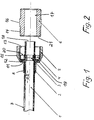
- a union nut 5 and then a cylindrical pressure sleeve 2 are placed over the outside 7 of the pipe 1 to be connected.
- the cylindrical pressure sleeve 2 has a cylindrical sleeve 8, one end face 9 of which forms an annular outer flange 10 is expanded. With its cylindrical sleeve 8, the pressure sleeve 2 extends through the inner opening 11 of the inner flange 12 of the union nut 5. In this position, the cylindrical sleeve can also be slightly tapered, so that it can no longer be removed and thus the union nut and pressure sleeve form a unit . This makes the overall assembly easier.
- the union nut 5 is intended to be screwed to a nipple 6.
- an internal thread 13 is provided on the union nut 5 and an external thread 14 is provided on the nipple 6.
- the internal thread 13 and the external thread 14 each extend over a section of the axial length of the union nut 5 and the nipple 6 respectively known key surfaces (not shown) are provided.
- the nipple 6 is pulled with its inside 17 on the outside 7 of the tube 1 from its outer end 18.
- a sealing ring 4 is provided between the end 18 of the pipe 1 to be connected and the end face 9 of the outer flange 10 of the pressure sleeve 2.
- the ring 4 consists of a material which is softer than the materials from which the union nut 5 or the nipple 6 are made.
- the ring 4 consists for example of soft metal or plastic or rubber.
- the ring 4 has on its end face facing the outer flange 10 of the pressure sleeve 2 a sliding layer 19 which is provided to reduce the friction between the outer flange 10 and the pressure sleeve 2 when the union nut 5 is screwed onto the nipple 6.
- this sliding layer can generally be dispensed with.
- the annular end face 20 of the ring 4 opposite the sliding layer 19 is first brought into contact with the end face 21 of the nipple 6 facing the end 18 of the pipe 1 to be screwed and then pressed against it in a sealed manner when the union nut 5 is tightened .
- the ring 4 which, as can be seen in FIG. 1, has a rectangular cross section, is simultaneously pressed in a sealing manner against the outside 7 of the pipe 1 to be connected.
- a support sleeve 3 is arranged within the cross section 22 of the pipe 1.
- the support sleeve 3 is arranged just below the ring 4. It is somewhat longer than the axial width of the ring 4 and can consist of two longitudinal sections 23 and 24. One length section 23 is conical and the other length section 24 is cylindrical, the two length sections 23 and 24 having approximately the same axial length.
- the support sleeve can also be conical overall.
- the end faces 25 and 26 of the support sleeve 3 are clearly rounded.
- the support sleeve 3 is made of metal or plastic. It has a continuous cross-sectional opening 27, which is round, but tapers in the same direction as the conical length section 23.
- the end 18 of the pipe 1 is heated so that it becomes soft, and the support sleeve 3 is inserted into the cross section 22 of the pipe 1 with the conical length section 23 ahead.
- the support sleeve 3 can also be heated instead of the tube.
- the support sleeve 3 is inserted at least as deep into the end 18 of the tube 1 as the axial length of the later seat of the ring 4 corresponds to measured from the end 18.
- the cooling pipe 1 contracts over the support sleeve and holds it firmly and immovably at its predetermined location within the cross section 22.
- the support sleeve 3 can be inserted so far that, as shown, a free pipe end protrudes.
- the union nut 5 When assembling the pipe connector further, the union nut 5 is first pushed with its inner opening 11 over the outside 7 of the pipe 1, the internal thread 13 pointing to the end 18 of the pipe 1. This is followed by the pressure sleeve 2 with the cylindrical sleeve 8, which slides along with a slight play on the outside 7 of the tube 1 and through the inner opening 11 of the union nut 5. The outer flange 10 of the pressure sleeve 2 comes to rest on the axial inside of the inner flange 12. This is followed by the ring 4 made of soft material. However, if a widening by a support sleeve 3 is to be expected, it is advisable to mount the union nut in the manner described before the support sleeve is inserted.
- the nipple 6 with its cylindrical inside 17 is pushed over the outside 7 of the end 18 of the pipe 1 to be connected and screwed to the union nut 5.
- the soft ring 4 is pressed through the wall of the tube 1 from the outside against the support sleeve, so that in addition to the sealing of the pipe connector on the outside 7 of the tube, this also at the same time at the design point of the support sleeve 3 on the pipe 1 attached.
- the pressure sleeve 2 slides with its outer flange 10 over the sliding layer 19 of the ring 4 and with its cylindrical shaft 8 on the outside 7 of the tube 1 can also be set up so that the inner flange 12 slides on the stationary annular outer flange 10.
- nipple 6 can of course also serve to connect the pipe 1 not to another pipe but to any other component. All that is necessary for this is that the nipple 6, with its thread facing away from the pipe 1, is inserted sealingly into this other component.
Landscapes
- Engineering & Computer Science (AREA)
- General Engineering & Computer Science (AREA)
- Mechanical Engineering (AREA)
- Joints With Pressure Members (AREA)
- Lining Or Joining Of Plastics Or The Like (AREA)
- Non-Disconnectible Joints And Screw-Threaded Joints (AREA)
- Infusion, Injection, And Reservoir Apparatuses (AREA)
- External Artificial Organs (AREA)
- Measuring Fluid Pressure (AREA)
Claims (23)
- Dispositif pour relier un tube en matière plastique (1) à section ronde à un autre tube ou à une pièce de raccordement d'autres éléments de construction, comportant un raccord fileté (6) et au moins un écrou-raccord (5) associé à celui-ci, étant précisé qu'il est prévu une bague d'étanchéité (4) à l'intérieur de l'écrou-raccord (5), que l'écrou-raccord (5), la bague d'étanchéité (4) et le raccord fileté (6) présentent chacun un perçage pour le passage d'un tube (1) ou d'une pièce de raccordement, que la bague d'étanchéité (4) se compose d'un matériau facilement déformable élastiquement ou plastiquement et qu'il est prévu entre une bride intérieure (12) de l'écrou-raccord (5), pourvue d'une ouverture intérieure (11) pour un tube (1), et un côté frontal (21) du raccord fileté (6), des surfaces antagonistes planes, et enfin qu'il est également prévu un manchon d'appui non déformé (3) dont la longueur est au moins égale à la largeur axiale de la bague d'étanchéité (4), caractérisé en ce qu'une bride extérieure annulaire (10) d'un manchon de pression (2) est disposée entre le joint d'étanchéité (4) et la bride intérieure (12) de l'écrou-raccord (5), la bride intérieure (12) de l'écrou-raccord (5) glissant sur la bride extérieure (10) du manchon de pression (2).
- Dispositif selon la revendication 1, caractérisé en ce que le côté extérieur, au moins, du manchon d'appui (3), présente deux sections longitudinales différentes (23, 24).
- Dispositif selon la revendication 2, caractérisé en ce que l'une des sections longitudinales (24) du côté extérieur du manchon d'appui (3) a une forme cylindrique tandis que l'autre section longitudinale (23) a une forme conique.
- Dispositif selon la revendication 3, caractérisé en ce que la section longitudinale conique (23), au moins, du côté extérieur du manchon d'appui (3) a une longueur égale à la moitié de la longueur axiale du manchon d'appui (3).
- Dispositif selon l'une des revendications 3 et 4, caractérisé en ce que la partie de la section longitudinale conique (23) du manchon d'appui (3) qui présente le plus petit diamètre extérieur est tournée vers le côté frontal contigu du manchon d'appui (3).
- Dispositif selon l'une des revendications 2 à 5, caractérisé en ce que le bord extérieur de l'un au moins des côtés frontaux (25, 26) du manchon d'appui (3) comporte une partie arrondie.
- Dispositif selon l'une des revendications 2 à 6, caractérisé en ce que le bord intérieur de l'un au moins des côtés frontaux (25, 26) du manchon d'appui (3) comporte une partie arrondie.
- Dispositif selon l'une des revendications 1 à 7, caractérisé en ce que la bride extérieure annulaire (10) d'un manchon de pression (2) est disposée entre la bague d'étanchéité (4) et la bague intérieure (12) de l'écrou-raccord.
- Dispositif selon la revendication 2, caractérisé en ce que le côté intérieur de l'ouverture de section transversale continue (27) du manchon d'appui (3) comporte deux sections longitudinales différentes.
- Dispositif selon la revendication 9, caractérisé en ce que l'une des sections longitudinales du côté intérieur de l'ouverture de section transversale continue (27) a une forme cylindrique, tandis que l'autre a une forme conique.
- Dispositif selon la revendication 10, caractérisé en ce que les deux sections longitudinales (23, 24) ont à peu près la même longueur axiale.
- Dispositif selon l'une des revendications 10 à 11, caractérisé en ce que la section intérieure conique de l'ouverture de section transversale (27) est disposée dans le même sens, au-dessous de la section longitudinale conique (23) du côté extérieur du manchon d'appui (3).
- Dispositif selon l'une des revendications 1 à 12, caractérisé en ce que le bord (9), situé côté frontal, de la bride extérieure (10) du manchon de pression cylindrique (2) comporte une couche de glissement.
- Dispositif selon l'une des revendications 1 à 13, caractérisé en ce que les bords extérieurs du manchon de pression (2) comportent une partie arrondie.
- Dispositif selon la revendication 1, caractérisé en ce que le bord intérieur de l'ouverture intérieure (11) de la bride intérieure (12) de l'écrou-raccord (5) qui est tourné vers le filetage intérieur (13) comporte une partie biseautée.
- Dispositif selon la revendication 1, caractérisé en ce que le diamètre de l'ouverture intérieure (11) de la bride intérieure (12) de l'écrou-raccord (5) est au moins légèrement plus grand que le diamètre extérieur du manchon de pression (2).
- Dispositif selon la revendication 1, caractérisé en ce que le raccord fileté (6) comporte, sur le côté extérieur (16), au moins une surface d'entraînement.
- Dispositif selon la revendication 17, caractérisé en ce que la surface d'entraînement est une surface pour clé ou un perçage adapté pour l'action d'une clé.
- Dispositif selon la revendication 17, caractérisé en ce que la surface d'entraînement est disposée au centre axial entre deux filetages extérieurs (14) du raccord fileté (6).
- Dispositif selon la revendication 1, caractérisé en ce que l'écrou-raccord (5) comporte, sur le côté extérieur (15), au moins une surface d'entraînement.
- Dispositif selon la revendication 20, caractérisé en ce que la surface d'entraînement (15) est une surface pour clé ou un perçage adapté pour l'action d'une clé.
- Dispositif selon la revendication 1, caractérisé en ce que le raccord fileté (6) est en métal ou en matière plastique.
- Dispositif selon la revendication 1, caractérisé en ce que l'écrou-raccord (5) est en métal ou en matière plastique.
Applications Claiming Priority (2)
| Application Number | Priority Date | Filing Date | Title |
|---|---|---|---|
| DE9004907U DE9004907U1 (de) | 1990-04-30 | 1990-04-30 | Vorrichtung zum Verbinden eines Kunststoffrohres mit einem weiteren Rohr |
| DE9004907U | 1990-04-30 |
Publications (3)
| Publication Number | Publication Date |
|---|---|
| EP0454976A2 EP0454976A2 (fr) | 1991-11-06 |
| EP0454976A3 EP0454976A3 (en) | 1992-03-04 |
| EP0454976B1 true EP0454976B1 (fr) | 1995-08-23 |
Family
ID=6853377
Family Applications (1)
| Application Number | Title | Priority Date | Filing Date |
|---|---|---|---|
| EP91103952A Expired - Lifetime EP0454976B1 (fr) | 1990-04-30 | 1991-03-14 | Dispositif pour relier un tuyau en matière synthétique à un autre tuyau |
Country Status (5)
| Country | Link |
|---|---|
| EP (1) | EP0454976B1 (fr) |
| AT (1) | ATE126870T1 (fr) |
| DE (2) | DE9004907U1 (fr) |
| DK (1) | DK0454976T3 (fr) |
| ES (1) | ES2076390T3 (fr) |
Families Citing this family (1)
| Publication number | Priority date | Publication date | Assignee | Title |
|---|---|---|---|---|
| EP1787917B1 (fr) | 2005-11-18 | 2009-04-08 | Airsec S.A.S. | Récipient et capsule comportant un transpondeur |
Family Cites Families (4)
| Publication number | Priority date | Publication date | Assignee | Title |
|---|---|---|---|---|
| DE7434125U (fr) * | 1975-01-30 | Gebr Beul & Co | ||
| US3493250A (en) * | 1967-12-18 | 1970-02-03 | Parker Hannifin Corp | Coupling for thermoplastic tube |
| US3881754A (en) * | 1971-05-06 | 1975-05-06 | Joe William Christie | Resilient internal support for plastic pipe |
| DE3832733A1 (de) * | 1988-09-27 | 1990-03-29 | Gerhard Rambacher | Rohrverbinder |
-
1990
- 1990-04-30 DE DE9004907U patent/DE9004907U1/de not_active Expired - Lifetime
-
1991
- 1991-03-14 AT AT91103952T patent/ATE126870T1/de not_active IP Right Cessation
- 1991-03-14 EP EP91103952A patent/EP0454976B1/fr not_active Expired - Lifetime
- 1991-03-14 DK DK91103952.7T patent/DK0454976T3/da active
- 1991-03-14 ES ES91103952T patent/ES2076390T3/es not_active Expired - Lifetime
- 1991-03-14 DE DE59106285T patent/DE59106285D1/de not_active Expired - Fee Related
Also Published As
| Publication number | Publication date |
|---|---|
| ATE126870T1 (de) | 1995-09-15 |
| EP0454976A2 (fr) | 1991-11-06 |
| DE9004907U1 (de) | 1990-08-02 |
| EP0454976A3 (en) | 1992-03-04 |
| DE59106285D1 (de) | 1995-09-28 |
| ES2076390T3 (es) | 1995-11-01 |
| DK0454976T3 (da) | 1995-12-18 |
Similar Documents
| Publication | Publication Date | Title |
|---|---|---|
| DE69701379T2 (de) | Rohrverbindung | |
| DE68903376T2 (de) | Einsteck-schlauchkupplung mit einem o-ring, der auf einem kegel mit kleinem winkel abgerollt wird. | |
| DE69908179T2 (de) | Rohrverbindung | |
| DE19740144A1 (de) | Verbindung eines Metallrohres mit einer Metallhülse | |
| DE69520264T2 (de) | Rohrverbindung | |
| EP0214395B1 (fr) | Raccord élastique de tuyaux et spécialement raccord flexible | |
| DE3010425A1 (de) | Vorrichtung zum befestigen eines schlauches auf einem rohrstutzen | |
| DE2312478A1 (de) | Rohrkupplung | |
| DE3838935A1 (de) | Kupplungsstueck | |
| DE60204287T2 (de) | Kupplung zur verbindung eines rohrs oder schlauchs durch einschieben | |
| DE69408861T2 (de) | Rohrverbindung | |
| EP0515930B1 (fr) | Dispositif de jonction pour fabriquer un raccord de tuyaux non-démontable | |
| WO2019002323A1 (fr) | Manchon de sertissage | |
| DE2735704C3 (de) | Am Gebrauchsort befestigbares Verbindungsstück für einen Schlauch | |
| DE69602925T2 (de) | Rohrkupplung und verfahren zum verbinden eines rohres an einem verbindungsstück | |
| EP0454976B1 (fr) | Dispositif pour relier un tuyau en matière synthétique à un autre tuyau | |
| EP1029192A1 (fr) | Piece de raccordement et d'assemblage pour tubes ondules | |
| EP0306770B1 (fr) | Liaison mécanique pour tuyaux à air comprimé en matière plastique | |
| DE102024108365A1 (de) | Rohrverbinder mit Halteeinrichtung | |
| EP2295842B1 (fr) | Raccord de tuyau destiné à raccorder de manière étanche une extrémité d'un tuyau en matière flexible | |
| EP0472056B1 (fr) | Element de raccord pour tuyaux | |
| DE4211959C2 (fr) | ||
| DE20121607U1 (de) | Anschlussvorrichtung für einen ringgewellten Metallschlauch | |
| EP0985867A1 (fr) | Tuyau ondulé en plastique et combinaison de ce tuyau avec un manchon | |
| DE1970807U (de) | Schlauchfassung. |
Legal Events
| Date | Code | Title | Description |
|---|---|---|---|
| PUAI | Public reference made under article 153(3) epc to a published international application that has entered the european phase |
Free format text: ORIGINAL CODE: 0009012 |
|
| AK | Designated contracting states |
Kind code of ref document: A2 Designated state(s): AT BE CH DE DK ES FR GB GR IT LI LU NL SE |
|
| PUAL | Search report despatched |
Free format text: ORIGINAL CODE: 0009013 |
|
| AK | Designated contracting states |
Kind code of ref document: A3 Designated state(s): AT BE CH DE DK ES FR GB GR IT LI LU NL SE |
|
| RHK1 | Main classification (correction) |
Ipc: F16L 47/04 |
|
| 17P | Request for examination filed |
Effective date: 19920902 |
|
| 17Q | First examination report despatched |
Effective date: 19930707 |
|
| GRAA | (expected) grant |
Free format text: ORIGINAL CODE: 0009210 |
|
| AK | Designated contracting states |
Kind code of ref document: B1 Designated state(s): AT BE CH DE DK ES FR GB GR IT LI LU NL SE |
|
| PG25 | Lapsed in a contracting state [announced via postgrant information from national office to epo] |
Ref country code: GR Free format text: LAPSE BECAUSE OF FAILURE TO SUBMIT A TRANSLATION OF THE DESCRIPTION OR TO PAY THE FEE WITHIN THE PRESCRIBED TIME-LIMIT Effective date: 19950823 |
|
| REF | Corresponds to: |
Ref document number: 126870 Country of ref document: AT Date of ref document: 19950915 Kind code of ref document: T |
|
| REF | Corresponds to: |
Ref document number: 59106285 Country of ref document: DE Date of ref document: 19950928 |
|
| ET | Fr: translation filed | ||
| GBT | Gb: translation of ep patent filed (gb section 77(6)(a)/1977) |
Effective date: 19950908 |
|
| ITF | It: translation for a ep patent filed | ||
| REG | Reference to a national code |
Ref country code: ES Ref legal event code: FG2A Ref document number: 2076390 Country of ref document: ES Kind code of ref document: T3 |
|
| REG | Reference to a national code |
Ref country code: DK Ref legal event code: T3 |
|
| PLBE | No opposition filed within time limit |
Free format text: ORIGINAL CODE: 0009261 |
|
| STAA | Information on the status of an ep patent application or granted ep patent |
Free format text: STATUS: NO OPPOSITION FILED WITHIN TIME LIMIT |
|
| 26N | No opposition filed | ||
| PGFP | Annual fee paid to national office [announced via postgrant information from national office to epo] |
Ref country code: GB Payment date: 19970226 Year of fee payment: 7 |
|
| PGFP | Annual fee paid to national office [announced via postgrant information from national office to epo] |
Ref country code: AT Payment date: 19970228 Year of fee payment: 7 |
|
| PGFP | Annual fee paid to national office [announced via postgrant information from national office to epo] |
Ref country code: FR Payment date: 19970313 Year of fee payment: 7 |
|
| PGFP | Annual fee paid to national office [announced via postgrant information from national office to epo] |
Ref country code: LU Payment date: 19970319 Year of fee payment: 7 |
|
| PGFP | Annual fee paid to national office [announced via postgrant information from national office to epo] |
Ref country code: SE Payment date: 19970320 Year of fee payment: 7 Ref country code: BE Payment date: 19970320 Year of fee payment: 7 |
|
| PGFP | Annual fee paid to national office [announced via postgrant information from national office to epo] |
Ref country code: ES Payment date: 19970324 Year of fee payment: 7 Ref country code: DK Payment date: 19970324 Year of fee payment: 7 |
|
| PGFP | Annual fee paid to national office [announced via postgrant information from national office to epo] |
Ref country code: NL Payment date: 19970331 Year of fee payment: 7 |
|
| PGFP | Annual fee paid to national office [announced via postgrant information from national office to epo] |
Ref country code: CH Payment date: 19970422 Year of fee payment: 7 |
|
| PG25 | Lapsed in a contracting state [announced via postgrant information from national office to epo] |
Ref country code: LU Free format text: LAPSE BECAUSE OF NON-PAYMENT OF DUE FEES Effective date: 19980314 Ref country code: GB Free format text: LAPSE BECAUSE OF NON-PAYMENT OF DUE FEES Effective date: 19980314 Ref country code: AT Free format text: LAPSE BECAUSE OF NON-PAYMENT OF DUE FEES Effective date: 19980314 |
|
| PG25 | Lapsed in a contracting state [announced via postgrant information from national office to epo] |
Ref country code: SE Free format text: LAPSE BECAUSE OF NON-PAYMENT OF DUE FEES Effective date: 19980315 |
|
| PG25 | Lapsed in a contracting state [announced via postgrant information from national office to epo] |
Ref country code: ES Free format text: LAPSE BECAUSE OF EXPIRATION OF PROTECTION Effective date: 19980316 |
|
| PG25 | Lapsed in a contracting state [announced via postgrant information from national office to epo] |
Ref country code: LI Free format text: LAPSE BECAUSE OF NON-PAYMENT OF DUE FEES Effective date: 19980331 Ref country code: FR Free format text: THE PATENT HAS BEEN ANNULLED BY A DECISION OF A NATIONAL AUTHORITY Effective date: 19980331 Ref country code: DK Free format text: LAPSE BECAUSE OF NON-PAYMENT OF DUE FEES Effective date: 19980331 Ref country code: CH Free format text: LAPSE BECAUSE OF NON-PAYMENT OF DUE FEES Effective date: 19980331 Ref country code: BE Free format text: LAPSE BECAUSE OF NON-PAYMENT OF DUE FEES Effective date: 19980331 |
|
| BERE | Be: lapsed |
Owner name: SCHMITZ-STOTZ PATRICIA Effective date: 19980331 Owner name: SCHMITZ JOHANNES Effective date: 19980331 |
|
| PG25 | Lapsed in a contracting state [announced via postgrant information from national office to epo] |
Ref country code: NL Free format text: LAPSE BECAUSE OF NON-PAYMENT OF DUE FEES Effective date: 19981001 |
|
| GBPC | Gb: european patent ceased through non-payment of renewal fee |
Effective date: 19980314 |
|
| REG | Reference to a national code |
Ref country code: CH Ref legal event code: PL |
|
| NLV4 | Nl: lapsed or anulled due to non-payment of the annual fee |
Effective date: 19981001 |
|
| EUG | Se: european patent has lapsed |
Ref document number: 91103952.7 |
|
| REG | Reference to a national code |
Ref country code: FR Ref legal event code: ST |
|
| REG | Reference to a national code |
Ref country code: DK Ref legal event code: EBP |
|
| REG | Reference to a national code |
Ref country code: ES Ref legal event code: FD2A Effective date: 20000301 |
|
| PGFP | Annual fee paid to national office [announced via postgrant information from national office to epo] |
Ref country code: DE Payment date: 20030509 Year of fee payment: 13 |
|
| PG25 | Lapsed in a contracting state [announced via postgrant information from national office to epo] |
Ref country code: DE Free format text: LAPSE BECAUSE OF NON-PAYMENT OF DUE FEES Effective date: 20041001 |
|
| PG25 | Lapsed in a contracting state [announced via postgrant information from national office to epo] |
Ref country code: IT Free format text: LAPSE BECAUSE OF NON-PAYMENT OF DUE FEES;WARNING: LAPSES OF ITALIAN PATENTS WITH EFFECTIVE DATE BEFORE 2007 MAY HAVE OCCURRED AT ANY TIME BEFORE 2007. THE CORRECT EFFECTIVE DATE MAY BE DIFFERENT FROM THE ONE RECORDED. Effective date: 20050314 |