EP0455001B1 - Arrangement de circuit pour des générateurs de rayons X, en particulier en vue d'applications diagnostiques - Google Patents
Arrangement de circuit pour des générateurs de rayons X, en particulier en vue d'applications diagnostiques Download PDFInfo
- Publication number
- EP0455001B1 EP0455001B1 EP91105238A EP91105238A EP0455001B1 EP 0455001 B1 EP0455001 B1 EP 0455001B1 EP 91105238 A EP91105238 A EP 91105238A EP 91105238 A EP91105238 A EP 91105238A EP 0455001 B1 EP0455001 B1 EP 0455001B1
- Authority
- EP
- European Patent Office
- Prior art keywords
- tube
- voltage
- ray
- values
- personal computer
- Prior art date
- Legal status (The legal status is an assumption and is not a legal conclusion. Google has not performed a legal analysis and makes no representation as to the accuracy of the status listed.)
- Revoked
Links
- 238000010438 heat treatment Methods 0.000 claims abstract description 25
- 230000005855 radiation Effects 0.000 claims abstract description 18
- 238000012544 monitoring process Methods 0.000 claims description 7
- 238000005259 measurement Methods 0.000 claims description 4
- 230000001105 regulatory effect Effects 0.000 claims 2
- 238000000034 method Methods 0.000 description 6
- 238000012937 correction Methods 0.000 description 4
- 238000010586 diagram Methods 0.000 description 3
- 238000012360 testing method Methods 0.000 description 3
- 238000012790 confirmation Methods 0.000 description 2
- 230000006866 deterioration Effects 0.000 description 2
- 238000003745 diagnosis Methods 0.000 description 2
- 238000012546 transfer Methods 0.000 description 2
- 230000006978 adaptation Effects 0.000 description 1
- 230000032683 aging Effects 0.000 description 1
- 230000033228 biological regulation Effects 0.000 description 1
- 230000005540 biological transmission Effects 0.000 description 1
- 230000000903 blocking effect Effects 0.000 description 1
- 238000013500 data storage Methods 0.000 description 1
- 238000012217 deletion Methods 0.000 description 1
- 230000037430 deletion Effects 0.000 description 1
- 238000005516 engineering process Methods 0.000 description 1
- 238000002594 fluoroscopy Methods 0.000 description 1
- 230000006870 function Effects 0.000 description 1
- 210000000056 organ Anatomy 0.000 description 1
- 238000002360 preparation method Methods 0.000 description 1
- 238000011084 recovery Methods 0.000 description 1
- 238000002560 therapeutic procedure Methods 0.000 description 1
- 230000001960 triggered effect Effects 0.000 description 1
- 238000011144 upstream manufacturing Methods 0.000 description 1
- 239000002699 waste material Substances 0.000 description 1
Images

Classifications
-
- H—ELECTRICITY
- H05—ELECTRIC TECHNIQUES NOT OTHERWISE PROVIDED FOR
- H05G—X-RAY TECHNIQUE
- H05G1/00—X-ray apparatus involving X-ray tubes; Circuits therefor
- H05G1/08—Electrical details
- H05G1/26—Measuring, controlling or protecting
- H05G1/54—Protecting or lifetime prediction
-
- H—ELECTRICITY
- H05—ELECTRIC TECHNIQUES NOT OTHERWISE PROVIDED FOR
- H05G—X-RAY TECHNIQUE
- H05G1/00—X-ray apparatus involving X-ray tubes; Circuits therefor
- H05G1/08—Electrical details
- H05G1/26—Measuring, controlling or protecting
- H05G1/30—Controlling
-
- H—ELECTRICITY
- H05—ELECTRIC TECHNIQUES NOT OTHERWISE PROVIDED FOR
- H05G—X-RAY TECHNIQUE
- H05G1/00—X-ray apparatus involving X-ray tubes; Circuits therefor
- H05G1/08—Electrical details
- H05G1/26—Measuring, controlling or protecting
- H05G1/30—Controlling
- H05G1/46—Combined control of different quantities, e.g. exposure time as well as voltage or current
Definitions
- the invention relates to a circuit arrangement for setting the recording parameters "high voltage”, “tube current” and “exposure time” for a diagnostic X-ray generator for an examination of an object to be carried out.
- the voltage of the X-ray tube (tube voltage) is preselected in order to ensure that the radiation is sufficiently soft or sufficiently hard for the intended use;
- the heating current of the hot cathode of the X-ray tube is preselected in order to obtain a desired cathode current and thus a certain radiation yield, which also depends on the condition of the anode;
- the duration of the radiation is preselected in order to be able to apply the desired radiation dose required for diagnosis or therapy at a dose rate given by the radiation hardness and radiation yield.
- these values are set on the control panel, this being done by preselecting the high voltage on the variable transformer of the high-voltage rectifier and by setting the heating current. While the heating current already flows before the high voltage is switched on (preheated cathode) and so the measurement of the actually flowing heating current with corresponding converters does not cause any problems, the high voltage is only applied during the application time, so it can only be preset "cold", a procedure that is different from plant to plant due to the load dependency of the high voltage with flowing cathode current depending on the manageable internal resistances of the high-voltage rectifiers and the unmanageable source resistances of the network and brings considerable difficulties especially for trained personnel. In addition, especially during longer application times, a drop in due to a sudden connection of a consumer or a sudden recovery of the mains voltage by switching off a consumer can result in an unforeseeable change in the high voltage, which changes the dose rate in an unforeseeable manner.
- WO-A-8 603 363 discloses a circuit arrangement for setting the recording parameters such as high voltage, tube current and exposure time for an X-ray examination to be carried out, with an interface, which is provided with input ports, on the one hand for connecting a personal computer and on the other hand for connection to the high-voltage generator of the x-ray system for recording electrical signals, by means of which these recording parameters can be set, a monitoring block being connected upstream of the high-voltage generator, whereby the interface includes a CPU, a ROM and a RAM as program and data storage for storing information that defines the logical conditions for the X-ray exposure, which must be adhered to according to the specifications, a clock for clocking the CPU and its ports with logical states , specified by this CPU, and connection means between these ports and the input ports for converting the logic states into the electrical signals, and a data bus, which is connected via the input ports to the personal computer, for storing the data associated with the parameters of the microcontroll ers are related, wherein the exercise of
- the processor calculates the power starting from a first current value in an iteration process and the energy with which the anode is loaded for the exposure time resulting for a desired charge transfer. If this value is above the limit, the tube current and tube voltage are reduced in a second step, the procedure is repeated, checked and - if the limit load energy is undershot - the exposure is released, otherwise the procedure is repeated until the first triplet of values is found, at which the limit energy remains below.
- the functionally related values for tube current and heating current are stored in the memory of the processor. The circuit arrangement leads to an exposure below the limit load.
- EP-A-0 001 640 relates to a radiological device which is intended in particular for examining patients and with which the image quality is to be optimized and the service life of the radiation source is to be maximized.
- a controller with a memory program computer is used used, the application memory contains a number of instruction programs.
- the factors entered for a recording of tube voltage, tube current and recording time or organ-specific requests are then taken into account by the memory program computer to the maximum tube current, taking into account the direction of radiation and the age and thickness of the patient, in order to achieve a minimum recording time; the resulting loads are compared with the X-ray tube load diagrams stored in the information store, exposure being permitted only if the limit load is not exceeded.
- the program lowers the tube current with a constant charge flow (ie increase in the recording time). These new values are again compared for compatibility with the X-ray tube exposure, etc. A deterioration in the image resolution is accepted. In order to keep this deterioration in image resolution within limits, an upper limit of the recording time can be specified, which must not be exceeded. If this occurs, the power output to the anode is reduced, the tube current is reduced and the tube voltage is increased, while keeping the film blackening factor constant (which is why the decrease in the tube current is disproportionately more important than the increase in the tube voltage), so that the decrease in the power delivered to the anode is reached. According to the publication, this procedure is repeated with other parameters (different focal spot size, higher speed of the rotating anode) until either a suitable triplet of values has been found or the technical feasibility of the recording with the selected or resulting specifications has been proven.
- the aim of these arrangements is that the x-ray system can be set to the parameters necessary for the different exposures in such a way that false exposures, which the patients need unnecessarily strain and waste expensive footage, be avoided.
- the connection to its control technology is achieved in a simple manner;
- this use requires a special interface that takes over the connection between the controller and the personal computer PC.
- This interface is constructed in such a way that on the one hand it transfers the analog (or already digitally converted on the encoder) feedback of the states of the actuators and the electrical and / or radiation measurements to the personal computer, which takes into account the technical data permanently stored in its application memory Values for the X-ray tube, for the high-voltage generator and the electrical supply network to which the high-voltage generator is connected, the current values for the X-ray tube and the present application, such as the heating power to be provided and the required high voltage (excessive due to the network load).
- the input informs the personal computer which application is present, the selection (and possibly the change) of the proposed standard values for the radiation dose rate values for high voltage and heating power for the X-ray tube then takes place in dialogue.
- the dialogue is carried out on a screen connected to the personal computer; the input is made via a keyboard connected to it.
- the program required for this is provided by the on-screen menu, which offers the operator sufficient options with logos and entries offers. Since the application memory has stored the values for the standard setting for these use cases, the “setting” of the X-ray generator can be carried out in a simple manner and without special technical knowledge. In addition, (with appropriate specialist knowledge) corrections of these standard values are possible at any time.
- safety-related operating values of the X-ray tube are stored in the application memory.
- the personal computer constantly compares the current operating values with the safety-relevant values in the memory which are to be regarded as limit values and keeps the current values in the range specified by these limit values.
- Security problems are inevitably avoided. Storing these values also allows these values to be adjusted if changes need to be made, for example due to a change in the safety concept.
- This also applies to the application-specific values stored in the application memory. While these are constantly updated by simply overwriting or adding, those require special treatment because of the security-related problems: The files must be secured against unauthorized overwriting; It is advantageous to use EPROMs, which require special treatment for deletion and rewriting (which is particularly important with regard to future changes to the security regulations).
- the radiation yield of the X-ray tube depends on the condition of its anode and this changes with increasing age, it is necessary to monitor the radiation yield continuously or from time to time. This is done with a measuring device switched into the beam path, which triggers the load switch when the desired dose value is reached and thus switches off the high voltage.
- This switch-off pulse is also used as an acknowledgment pulse for the personal computer PC and is supplied to it via the interface. This tells the personal computer that the application is complete. This message causes a switching state that, for example, rules out a new application without confirmation. This is necessary to exclude double exposures when taking pictures; the need for such a blocking circuit also results from safety requirements.
- the personal computer has further interfaces, one of which is used as a printer interface, to which a printer is connected as a further output unit.
- the personal computer is able to output a protocol for each application on the course of tube voltage and tube current as well as the dose rate and the duration of the application. This means that these printouts can be collected for documentation purposes, for example in the patient file. It goes without saying that electronic storage can also be carried out and a printout can only be made if necessary.
- a connection to a higher-level computer is also possible with this or another interface. This higher-level computer can transmit the application data for the selected application, it can contain the security-relevant data and, finally, it can also take over the task of the memory for the data to be documented.
- the personal computer - referred to here as a computer "PC” - has at least three interfaces, one of which is occupied by an input unit, the "keyboard", and another by the output unit, the "screen”.
- the "interface” with which the connection to the individual components of the X-ray generator is established is connected to the third interface.
- the third interface which takes up the connection of the "interface”, is set up as an IN / OUT port, via which position feedback and measured value signals, as well as acknowledgment signals to the computer, and control commands to the connected components run.
- the desired application is selected via the input unit "keyboard" with the help of a corresponding menu provided by the program, and if the computer has also calculated the necessary high voltage and the heating power required for the necessary tube current based on this program, the associated control commands are issued by the Part "tube voltage” of the interface to the "control transformer” and part “tube current” of the interface to the "tap changer for heating", the actuators of which then execute the control commands.
- the high voltage selected by the PC is then applied to the "load switch", with a value that is excessive according to the expected reduction under load.
- the heating is started up with an undervoltage as preheating, the switch "preheating / heating” is still in the position (not shown) "preheating with unstabilized voltage”.
- the dose rate calculated by PC also affects the anode load, it should also be monitored.
- the rotating anode is activated via the "dose automat" part of the interface, the beam focusing is adjusted in the desired or necessary manner via “focus” and finally the feedback of the measuring chamber is recorded via the "dose control" locks the PC for further applications without a new confirmation.
- Such feedback occurs even after the rotating anode has started, without this feedback the switching on of the load switch and thus the application of the high voltage to the X-ray tube is excluded.
- the dose machine connected to the interface itself is generally not part of the X-ray generator, but is to be seen as an autonomously working part of the X-ray system.
- the "load switch” part of the interface activates the high-voltage load switch, coupled with the changeover from "preheating with unstabilized voltage” to “heating with stabilized voltage”.
- the use of a stabilized voltage ensures the desired heating power and thus the temperature of the heated cathode required for a specific tube current. Switching in the heating circuit allows adaptation to the different requirements, for example for exposure or fluoroscopy.
- the interface also has measured value inputs, some of which go to the interface via the A / D converter of the "measured value converter” and partly directly via the “preparation for recording”.
- the incoming measured values serve on the one hand to monitor the progress of the entire application, but on the other hand the measured values provide feedback e.g. about changes in the source resistance of the high-voltage rectifier (including the electrical connection network) and thus about the overvoltage to be set without load or the emissivity of the cathode as a function of the temperature of the cathode and thus the cathode heating power supplied.
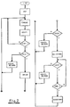
- the control takes place via the personal computer PC, which is loaded with a program, the structure of which can be seen in the flow diagram attached to FIG.
- a system test is carried out under "INIT” and set all variable values to the starting position.
- the system is then ready to accept the values determined for the given circumstances under "Input”. These values are checked for their conclusiveness under "Verify” and in the following YES / NO decision under "Start” the further program sequence is triggered given the start command. If the specifications are not conclusive, or if the start command is not given, the system jumps back to the input and thus also allows an input correction.
- the automatic exposure starts under "Exposure", during which the high voltage at the tube, the tube current, the heating current and the exposure time are measured. Errors that occur, i.e. Deviations from the specifications are identified by the system and reported as an error. During the exposure this test is repeated continuously by querying the parameters in a loop. After the passage of time, i.e. At the end of the exposure time, the measured values are displayed, including the current-time product in mAs that is important for the dose, which can also be documented, if necessary, by transmission to a higher-level computer, the personal computer PC hosted. The system then jumps back to "Enter” and is ready to accept new parameters.
Landscapes
- Health & Medical Sciences (AREA)
- General Health & Medical Sciences (AREA)
- Toxicology (AREA)
- X-Ray Techniques (AREA)
- Apparatus For Radiation Diagnosis (AREA)
- Details Of Television Scanning (AREA)
- Ultra Sonic Daignosis Equipment (AREA)
Claims (5)
- Montage pour régler les paramètres de prise de vues "haute tension", "courant du tube" et "durée d'exposition" pour un générateur de rayons X de diagnostic pour l'examen devant être effectué d'un objet, comportant une interface pour le transfert de signaux électriques, au moyen de laquelle ces paramètres de prise de vues peuvent être positionnés, et pour l'envoi de signalisation en retour et, par l'intermédiaire des sorties et des entrées duquel sont raccordés d'une part un ordinateur personnel (PC) et d'autre part un redresseur haute tension comportant un transformateur de réglage, un générateur réglable de la tension de chauffage comportant un commutateur à gradins ainsi qu'un tube à rayons X relié au redresseur haute tension, et dans lequel l'ordinateur personnel comprend des moyens pour contrôler les paramètres de prise de vues, ainsi qu'une mémoire d'utilisation pour la mémorisation d'informations, qui d'une part concernent les valeurs limites, importantes pour la sécurité, pour le fonctionnement du tube à rayons X et d'autre part fixent les paramètres de prise de vues devant être respectés en fonction de prescriptions, et dans lequel l'ordinateur personnel (PC) calcule tout d'abord la tension du tube et la puissance de chauffage pour une dose de rayons X présentant une dureté désirée, et dans lequel des valeurs actuelles, mesurées pendant la durée d'exposition, de la tension et du courant du tube sont envoyées en permanence, par l'intermédiaire d'une surface, à l'ordinateur personnel (PC), et dans lequel l'ordinateur personnel compare en permanence ces valeurs mesurées aux valeurs limites importantes pour la sécurité et conserve les valeurs actuelles dans la gamme prédéterminée par ces valeurs limites, et dans lequel un réglage, qui en résulte, du redresseur haute tension ainsi que du générateur de haute tension est appliqué, en tenant compte de la charge limite du tube à rayons X, au transformateur de réglage du redresseur haute tension et au circuit de réglage du générateur de haute tension de sorte que la durée d'exposition est réduite tout en respectant une valeur présélectionnée pour la valeur de charge (mAs).
- Montage selon la revendication 1, caractérisé en ce que pour le contrôle permanent de la tension du tube, il est prévu une boucle de programme, les valeurs de mesure étant affichées et recensées après le déroulement d'une durée d'exposition.
- Montage selon la revendication 1 ou 2, caractérisé en ce que dans le trajet du faisceau est monté, en aval de l'objet, un appareil de mesure de rayonnement servant à mesurer la dose délivrée par le tube à rayons X, un interrupteur de charge débranchant de façon connue en soi le générateur de rayons X, lorsque la valeur désirée de dose est atteinte.
- Montage selon la revendication 3, caractérisé en ce que des écarts de la signalisation en retour de la chambre de mesure, dont la valeur de mesure fournit, en fonction de la tension et du courant du tube, une mesure du rendement de rayonnement de l'anode, sont mémorisés en tant que valeurs de référence dans la mémoire d'utilisation et sont pris en compte, lors de contrôles ultérieurs de constance de l'installation à rayons X, par le fait que l'ordinateur personnel (PC) compare ces valeurs aux valeurs de sortie obtenues lors de la mesure de contrôle de l'installation radiologique.
- Montage selon l'une des revendications 1 à 4, caractérisé en ce qu'une imprimante est raccordée de façon connue en soi à une sortie d'imprimante de l'ordinateur personnel (PC), pour la délivrance d'un protocole global de l'examen actuel avec des indications concernant la variation des valeurs effectives de la tension et du courant du tube ainsi que de la puissance de dose et de la durée d'exposition.
Applications Claiming Priority (2)
| Application Number | Priority Date | Filing Date | Title |
|---|---|---|---|
| DE4013703 | 1990-04-28 | ||
| DE4013703A DE4013703C2 (de) | 1990-04-28 | 1990-04-28 | Schaltungsanordnung für insbesondere für Diagnosezwecke eingesetzte Röntgengeneratoren |
Publications (3)
| Publication Number | Publication Date |
|---|---|
| EP0455001A2 EP0455001A2 (fr) | 1991-11-06 |
| EP0455001A3 EP0455001A3 (en) | 1992-03-11 |
| EP0455001B1 true EP0455001B1 (fr) | 1995-11-02 |
Family
ID=6405339
Family Applications (1)
| Application Number | Title | Priority Date | Filing Date |
|---|---|---|---|
| EP91105238A Revoked EP0455001B1 (fr) | 1990-04-28 | 1991-04-03 | Arrangement de circuit pour des générateurs de rayons X, en particulier en vue d'applications diagnostiques |
Country Status (4)
| Country | Link |
|---|---|
| EP (1) | EP0455001B1 (fr) |
| AT (1) | ATE129843T1 (fr) |
| DE (2) | DE4013703C2 (fr) |
| DK (1) | DK0455001T3 (fr) |
Families Citing this family (8)
| Publication number | Priority date | Publication date | Assignee | Title |
|---|---|---|---|---|
| DE4341289A1 (de) * | 1993-12-03 | 1995-06-08 | Siemens Ag | Medizinische Anlage |
| DE4341290A1 (de) * | 1993-12-03 | 1995-06-08 | Siemens Ag | Medizinische Anlage zur Therapie und/oder Diagnose |
| DE19520360C2 (de) * | 1995-06-07 | 2000-08-10 | Bork Klaus Peter | Verfahren zur Durchführung von Konstanzprüfungen an für Diagnosezwecke eingesetzte Röntgengeneratoren |
| DE19635595C2 (de) * | 1996-09-02 | 2003-07-17 | Siemens Ag | Diagnostikeinrichtung mit Mitteln zur digitalen Bildspeicherung |
| DE19707728A1 (de) * | 1997-02-26 | 1998-08-27 | Siemens Ag | Röntgendiagnostikeinrichtung mit Filtermitteln |
| DE19750105B4 (de) * | 1997-11-12 | 2011-04-14 | Siemens Ag | Medizinische Therapie- und/oder Behandlungsanlage sowie Verfahren zum Betrieb einer solchen |
| DE10163583A1 (de) | 2001-12-21 | 2003-07-03 | Philips Intellectual Property | Verfahren und Vorrichtung zur Belichtung von Röntgenaufnahmen |
| DE102004042875B4 (de) * | 2003-10-07 | 2006-07-20 | Klaus-Peter Bork | Verfahren und Vorrichtung zum Schreiben und Führen eines Patienten-Röntgenpasses |
Family Cites Families (9)
| Publication number | Priority date | Publication date | Assignee | Title |
|---|---|---|---|---|
| US4158138A (en) * | 1977-10-25 | 1979-06-12 | Cgr Medical Corporation | Microprocessor controlled X-ray generator |
| DE3025107A1 (de) * | 1980-07-02 | 1982-01-14 | Siemens AG, 1000 Berlin und 8000 München | Roentgendiagnostikeinrichtung fuer aufnahme und durchleuchtung |
| DD158307A1 (de) * | 1981-04-23 | 1983-01-05 | Guenther Orth | Verfahren zur herstellung von roentgenaufnahmen |
| US4541106A (en) * | 1984-02-22 | 1985-09-10 | General Electric Company | Dual energy rapid switching imaging system |
| WO1986003363A1 (fr) * | 1984-11-21 | 1986-06-05 | Medicor | Dispositif de reglage des parametres d'exposition d'un equipement radiologique |
| DE3600464A1 (de) * | 1986-01-10 | 1987-07-16 | Philips Patentverwaltung | Roentgengenerator mit dosisleistungsregelung |
| EP0346530A1 (fr) * | 1988-06-16 | 1989-12-20 | Nicola Elias Yanaki | Procédé et dispositif pour optimiser la qualité radiographique par contrôle de la tension, du courant, de la dimension du foyer et du temps d'exposition d'un tube à rayons X |
| US4811374A (en) * | 1986-11-13 | 1989-03-07 | Medicor Usa Ltd. | Apparatus for setting exposure parameters of an X-ray generator |
| US4819258A (en) * | 1986-11-28 | 1989-04-04 | Bennett X-Ray Corp. | Auto-setting of KV in an x-ray machine after selection of technic factors |
-
1990
- 1990-04-28 DE DE4013703A patent/DE4013703C2/de not_active Expired - Fee Related
-
1991
- 1991-04-03 DE DE59106797T patent/DE59106797D1/de not_active Revoked
- 1991-04-03 AT AT91105238T patent/ATE129843T1/de not_active IP Right Cessation
- 1991-04-03 DK DK91105238.9T patent/DK0455001T3/da active
- 1991-04-03 EP EP91105238A patent/EP0455001B1/fr not_active Revoked
Also Published As
| Publication number | Publication date |
|---|---|
| ATE129843T1 (de) | 1995-11-15 |
| DE4013703C2 (de) | 1999-04-01 |
| EP0455001A2 (fr) | 1991-11-06 |
| DE59106797D1 (de) | 1995-12-07 |
| EP0455001A3 (en) | 1992-03-11 |
| DE4013703A1 (de) | 1991-10-31 |
| DK0455001T3 (da) | 1996-02-26 |
Similar Documents
| Publication | Publication Date | Title |
|---|---|---|
| EP0001640B1 (fr) | Appareil à rayons X | |
| DE3443276C2 (de) | Einrichtung und Verfahren zum Bestimmen der verbleibenden unklaren Lebensdauer eines Motors | |
| DE2345947C3 (de) | Schaltungsanordnung zur Überwachung der Belastung einer Röntgenröhre | |
| DE2827146A1 (de) | Anatomisch koordinierter, vom benutzer beherrschter programmierer fuer eine diagnostische roentgenvorrichtung | |
| DE2329414A1 (de) | Roentgendiagnostikapparat zur anfertigung von roentgenaufnahmen mit einem zeitschalter zur bestimmung der aufnahmedauer | |
| DE2715433B2 (de) | Verfahren zum Schnellabsenken der Leistung eines Druckwasserreaktors | |
| EP0455001B1 (fr) | Arrangement de circuit pour des générateurs de rayons X, en particulier en vue d'applications diagnostiques | |
| DE2704098A1 (de) | Elektro-hydraulische dampfturbinen- regeleinrichtung | |
| DE2826455A1 (de) | Roentgenapparat | |
| EP0063644B1 (fr) | Procédé de prises de vues radiographiques | |
| EP0022295A1 (fr) | Procédé de commande de la puissance électrique appliquée à un tube à rayons X à anode tournante | |
| DE3142305A1 (de) | "spannungskonstanthalter und -kompensationsverfahren" | |
| DE2328322A1 (de) | Roentgendiagnostikapparat zur verwendung mit einem hilfsgeraet, das eine vorgebbare aufnahmezeit erfordert | |
| DE2825323C2 (de) | Belichtungsautomat für einen Röntgengenerator | |
| EP0682466B1 (fr) | Installation de radiologie | |
| DE2526294A1 (de) | Bestrahlungsanlage fuer ionisierende strahlung | |
| DE961199C (de) | Roentgenapparat | |
| DE69018155T2 (de) | Apparat und Verfahren für Röntgenaufnahmen. | |
| DE68908342T2 (de) | Elektrotherapie-Gerät. | |
| DE2827087A1 (de) | Anatomisch koordinierter, vom benutzer beherrschter programmierer fuer eine diagnostische roentgenvorrichtung | |
| DE3606587A1 (de) | Roentgendiagnostikeinrichtung mit zeitrechner | |
| DE1236669C2 (de) | Drehstrom - roentgendiagnostikapparat | |
| DE19520360C2 (de) | Verfahren zur Durchführung von Konstanzprüfungen an für Diagnosezwecke eingesetzte Röntgengeneratoren | |
| DE2310454A1 (de) | Roentgendiagnostikeinrichtung mit funktionseinheiten zur energieversorgung und signalverarbeitung | |
| DE2206234A1 (de) | Verfahren zum betrieb eines fluessigkeitsgekuehlten leistungsreaktors und dazu dienender regelkreis |
Legal Events
| Date | Code | Title | Description |
|---|---|---|---|
| PUAI | Public reference made under article 153(3) epc to a published international application that has entered the european phase |
Free format text: ORIGINAL CODE: 0009012 |
|
| AK | Designated contracting states |
Kind code of ref document: A2 Designated state(s): AT BE CH DE DK FR GB IT LI NL SE |
|
| PUAL | Search report despatched |
Free format text: ORIGINAL CODE: 0009013 |
|
| AK | Designated contracting states |
Kind code of ref document: A3 Designated state(s): AT BE CH DE DK FR GB IT LI NL SE |
|
| 17P | Request for examination filed |
Effective date: 19920820 |
|
| 17Q | First examination report despatched |
Effective date: 19930317 |
|
| GRAA | (expected) grant |
Free format text: ORIGINAL CODE: 0009210 |
|
| AK | Designated contracting states |
Kind code of ref document: B1 Designated state(s): AT BE CH DE DK FR GB IT LI NL SE |
|
| REF | Corresponds to: |
Ref document number: 129843 Country of ref document: AT Date of ref document: 19951115 Kind code of ref document: T |
|
| REF | Corresponds to: |
Ref document number: 59106797 Country of ref document: DE Date of ref document: 19951207 |
|
| ITF | It: translation for a ep patent filed | ||
| REG | Reference to a national code |
Ref country code: CH Ref legal event code: NV Representative=s name: BOVARD AG PATENTANWAELTE |
|
| REG | Reference to a national code |
Ref country code: DK Ref legal event code: T3 |
|
| ET | Fr: translation filed | ||
| GBT | Gb: translation of ep patent filed (gb section 77(6)(a)/1977) |
Effective date: 19960205 |
|
| PGFP | Annual fee paid to national office [announced via postgrant information from national office to epo] |
Ref country code: DE Payment date: 19960321 Year of fee payment: 6 |
|
| PGFP | Annual fee paid to national office [announced via postgrant information from national office to epo] |
Ref country code: FR Payment date: 19960325 Year of fee payment: 6 |
|
| PGFP | Annual fee paid to national office [announced via postgrant information from national office to epo] |
Ref country code: GB Payment date: 19960401 Year of fee payment: 6 |
|
| PGFP | Annual fee paid to national office [announced via postgrant information from national office to epo] |
Ref country code: DK Payment date: 19960429 Year of fee payment: 6 Ref country code: AT Payment date: 19960429 Year of fee payment: 6 |
|
| PGFP | Annual fee paid to national office [announced via postgrant information from national office to epo] |
Ref country code: NL Payment date: 19960430 Year of fee payment: 6 |
|
| PGFP | Annual fee paid to national office [announced via postgrant information from national office to epo] |
Ref country code: CH Payment date: 19960501 Year of fee payment: 6 |
|
| PGFP | Annual fee paid to national office [announced via postgrant information from national office to epo] |
Ref country code: BE Payment date: 19960502 Year of fee payment: 6 |
|
| PLBI | Opposition filed |
Free format text: ORIGINAL CODE: 0009260 |
|
| PLBQ | Unpublished change to opponent data |
Free format text: ORIGINAL CODE: EPIDOS OPPO |
|
| 26 | Opposition filed |
Opponent name: SIEMENS AG Effective date: 19960613 |
|
| PLBI | Opposition filed |
Free format text: ORIGINAL CODE: 0009260 |
|
| PLBF | Reply of patent proprietor to notice(s) of opposition |
Free format text: ORIGINAL CODE: EPIDOS OBSO |
|
| NLR1 | Nl: opposition has been filed with the epo |
Opponent name: SIEMENS AG |
|
| 26 | Opposition filed |
Opponent name: PHILIPS ELECTRONICS N.V. Effective date: 19960731 Opponent name: SIEMENS AG Effective date: 19960613 |
|
| NLR1 | Nl: opposition has been filed with the epo |
Opponent name: PHILIPS ELECTRONICS N.V. Opponent name: SIEMENS AG |
|
| PLBF | Reply of patent proprietor to notice(s) of opposition |
Free format text: ORIGINAL CODE: EPIDOS OBSO |
|
| PGFP | Annual fee paid to national office [announced via postgrant information from national office to epo] |
Ref country code: SE Payment date: 19970307 Year of fee payment: 7 |
|
| PG25 | Lapsed in a contracting state [announced via postgrant information from national office to epo] |
Ref country code: GB Effective date: 19970403 Ref country code: DK Effective date: 19970403 Ref country code: AT Effective date: 19970403 |
|
| REG | Reference to a national code |
Ref country code: DK Ref legal event code: EBP |
|
| PG25 | Lapsed in a contracting state [announced via postgrant information from national office to epo] |
Ref country code: LI Free format text: LAPSE BECAUSE OF NON-PAYMENT OF DUE FEES Effective date: 19970430 Ref country code: CH Free format text: LAPSE BECAUSE OF NON-PAYMENT OF DUE FEES Effective date: 19970430 Ref country code: BE Effective date: 19970430 |
|
| BERE | Be: lapsed |
Owner name: BORK KLAUS-PETER Effective date: 19970430 |
|
| PG25 | Lapsed in a contracting state [announced via postgrant information from national office to epo] |
Ref country code: NL Effective date: 19971101 |
|
| GBPC | Gb: european patent ceased through non-payment of renewal fee |
Effective date: 19970403 |
|
| RDAH | Patent revoked |
Free format text: ORIGINAL CODE: EPIDOS REVO |
|
| REG | Reference to a national code |
Ref country code: CH Ref legal event code: PL |
|
| NLV4 | Nl: lapsed or anulled due to non-payment of the annual fee |
Effective date: 19971101 |
|
| REG | Reference to a national code |
Ref country code: FR Ref legal event code: ST |
|
| RDAG | Patent revoked |
Free format text: ORIGINAL CODE: 0009271 |
|
| STAA | Information on the status of an ep patent application or granted ep patent |
Free format text: STATUS: PATENT REVOKED |
|
| 27W | Patent revoked |
Effective date: 19971228 |
|
| PLAB | Opposition data, opponent's data or that of the opponent's representative modified |
Free format text: ORIGINAL CODE: 0009299OPPO |