EP0455003B1 - Système de commande d'un véhicule - Google Patents
Système de commande d'un véhicule Download PDFInfo
- Publication number
- EP0455003B1 EP0455003B1 EP91105442A EP91105442A EP0455003B1 EP 0455003 B1 EP0455003 B1 EP 0455003B1 EP 91105442 A EP91105442 A EP 91105442A EP 91105442 A EP91105442 A EP 91105442A EP 0455003 B1 EP0455003 B1 EP 0455003B1
- Authority
- EP
- European Patent Office
- Prior art keywords
- electronic
- vehicle
- block
- unit
- fact
- Prior art date
- Legal status (The legal status is an assumption and is not a legal conclusion. Google has not performed a legal analysis and makes no representation as to the accuracy of the status listed.)
- Expired - Lifetime
Links
Images

Classifications
-
- B—PERFORMING OPERATIONS; TRANSPORTING
- B60—VEHICLES IN GENERAL
- B60K—ARRANGEMENT OR MOUNTING OF PROPULSION UNITS OR OF TRANSMISSIONS IN VEHICLES; ARRANGEMENT OR MOUNTING OF PLURAL DIVERSE PRIME-MOVERS IN VEHICLES; AUXILIARY DRIVES FOR VEHICLES; INSTRUMENTATION OR DASHBOARDS FOR VEHICLES; ARRANGEMENTS IN CONNECTION WITH COOLING, AIR INTAKE, GAS EXHAUST OR FUEL SUPPLY OF PROPULSION UNITS IN VEHICLES
- B60K35/00—Instruments specially adapted for vehicles; Arrangement of instruments in or on vehicles
- B60K35/20—Output arrangements, i.e. from vehicle to user, associated with vehicle functions or specially adapted therefor
-
- B—PERFORMING OPERATIONS; TRANSPORTING
- B60—VEHICLES IN GENERAL
- B60K—ARRANGEMENT OR MOUNTING OF PROPULSION UNITS OR OF TRANSMISSIONS IN VEHICLES; ARRANGEMENT OR MOUNTING OF PLURAL DIVERSE PRIME-MOVERS IN VEHICLES; AUXILIARY DRIVES FOR VEHICLES; INSTRUMENTATION OR DASHBOARDS FOR VEHICLES; ARRANGEMENTS IN CONNECTION WITH COOLING, AIR INTAKE, GAS EXHAUST OR FUEL SUPPLY OF PROPULSION UNITS IN VEHICLES
- B60K35/00—Instruments specially adapted for vehicles; Arrangement of instruments in or on vehicles
- B60K35/10—Input arrangements, i.e. from user to vehicle, associated with vehicle functions or specially adapted therefor
-
- B—PERFORMING OPERATIONS; TRANSPORTING
- B60—VEHICLES IN GENERAL
- B60K—ARRANGEMENT OR MOUNTING OF PROPULSION UNITS OR OF TRANSMISSIONS IN VEHICLES; ARRANGEMENT OR MOUNTING OF PLURAL DIVERSE PRIME-MOVERS IN VEHICLES; AUXILIARY DRIVES FOR VEHICLES; INSTRUMENTATION OR DASHBOARDS FOR VEHICLES; ARRANGEMENTS IN CONNECTION WITH COOLING, AIR INTAKE, GAS EXHAUST OR FUEL SUPPLY OF PROPULSION UNITS IN VEHICLES
- B60K37/00—Dashboards
- B60K37/20—Dashboard panels
Definitions
- the present invention relates to an electronic control system for controlling motor vehicle members and equipment.
- Modern cars are known to feature a number of electronic and electromechanical systems, each controlling a respective part of the vehicle.
- some of these systems such as the ignition and electronic injection systems, are integrated as described in the article of Patrick D. Jordan published in Electronics and Wireless World and entitled “Advanced engine management systems", while, on others, they are connected over data transmission lines, as described in the Patent DE-A-3504181 and in the article of Dan McCosh published in Popular Science and entitled “Smart circuits revolutionize auto wiring”.
- a vehicle control system consisting of a number of systems presents numerous drawbacks.
- each electronic system features its own electronic control unit and sensors for detecting physical parameters and the operating status of given vehicle components, with the result that, invariably, the same parameter or component operating status is detected by more than one sensor, i.e. one for each control unit.
- a similar arrangement also involves the use of a large number of detecting members and electrical connections, and fails to make full use of certain parts of the electronic systems (e.g. the computing capacity of the control unit microprocessors) thus resulting in higher manufacturing and installation cost.
- a vehicle control system incorporating all the electronic equipment on the vehicle, comprising: a main electronic logic unit connected to the vehicle battery via a first electronic electrical supply block; a second electronic block indicating operating data and parameters, i.e.
- Number 1 in the accompanying drawings indicates an electronic vehicle control system installed inside the passenger compartment, in particular on the dashpanel, of the vehicle.
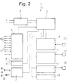
- System 1 comprises: a main logic unit 2 connected to the vehicle battery via an electrical supply block 3; a block 4 indicating operating data and parameters (the operating status of the engine and vehicle) and substantially representing the instrumentation on the vehicle; an interface block 5 to which are connected a number of sensors 6 designed, as described later, to detect data, parameters, operation and operating status relative to various vehicle members and components; an interface block 7 to which are connected a number of electromechanical controls 8; a block 11 for controlling electronic injectors 12; a block 13 for controlling a power module 14 of the electronic ignition system; and a block 15 for transmitting and receiving from unit 2 diagnostic data relative to the electronics of system 1, and consisting of a diagnostic tap 16 as shown in Fig.1.
- System 1 may feature additional optional blocks 17 for the purposes described later on.
- System 1 as described above therefore incorporates all the electronic equipment on the vehicle, which is controlled by one main unit requiring one sensor 6 for detecting each data item, parameter or vehicle component operating status.
- Sensors 6 are all electronic transducer types, which provide for numerous advantages (low cost, troublefree installation, low wear and substantially no maintenance) as compared with currently used mechanical transducers or detecting members in general.
- system 1 is installed on the dashpanel of the vehicle.
- system 1 consists of two housings 21 and 22 containing main unit 2 and blocks 3, 4, 5, 7, 11 and 13 connected to the same, and connected electrically by a line 23 (shown by the dotted line).
- Housing 21 presents a front panel 24 supporting block 4 and diagnostic tap 16.
- Block 4 comprises a number of indicators showing parameters and data relative to operation and the operating status of the vehicle engine and components.
- indicator 25 shows the speed per hour of the vehicle;
- indicator 26 the fuel level;
- indicator 27 the temperature of the engine cooling fluid;
- indicator 28 the pressure of the multistage centrifugal blower (if installed);
- indicator 31 the total mileage of the vehicle; and indicator 32 the partial mileage count.
- a button 33 is provided for resetting the partial mileage indicator, and which may be connected directly to block 4, as shown in Fig.2, or represented by one of electromechanical controls 8.
- Block 4 also comprises a number of indicator lights 34 for indicating the operating status of certain parts of the vehicle, such as the headlights or direction indicators.
- the indicators may of course provide for numerical and/or figurative display, wherein the parameter is shown, for example, in proportion to the overall extension of a light scale, as on a graduated scale.
- the electromechanical controls indicated herein by 8 are representative of both user-operated controls, for operating the lights, power window regulator, centralized door lock, seat and seatback regulator, windscreen wipers, etc., and main unit 2 control via block 7 of the actuators governing user-controlled operation of the vehicle members.
- Fig.2 shows direct electrical connecting lines from control 8 to block 7 and vice versa.
- Housing 22 presents a front panel 35 supporting a number of buttons 36 representing user-operated controls 8.
- the size of the dashpanel permitting provision may be made for one housing having a front panel fitted with all the components supported, in the example shown, on panels 24 and 35.
- block 5 is connected to a number of sensors 6 for detecting all the data processed and required by unit 2 for controlling the other blocks in system 1.
- the data normally detected substantially relates to engine cooling fluid temperature; air temperature and pressure in the intake manifold for mixing and atomising the fuel; engine speed and phase, which, together with the air intake data, provides for controlling electronic injection and ignition; fuel level in the tank, which, together with other data, provides for calculating fuel consumption; vehicle speed, which, together with other data, provides for calculating average traveling speed; oil level and temperature, etc..
- certain parameters may be calculated by processing the data supplied to unit 2 by sensors 6.
- the intake air temperature gives an approximate indication of the temperature outside the vehicle and, for example, the possibility of ice forming on the road surface, which may be shown by an alarm light or an additional all-purpose alarm indicator on block 4 for "dialoging" between system 1 and the user, e.g. for providing a fasten-seat-belt warning, or indicating speeding or an open door with the vehicle in motion.
- tap 16 need simply be connected to a known unit for indicating and/or displaying the data relative to the parts being controlled.
- System 1 is electronically and, therefore, physically compact, thus enabling it to be installed directly on the dashpanel inside the passenger compartment; presents fewer component parts (e.g. fewer sensors) enabling low-cost manufacture; and features a single main data processing unit employed to maximum capacity.
- location of system 1 safeguards the components and electrical connections from thermal and mechanical stress and electromagnetic interference normally present in the engine compartment. As such, system 1 provides for a high degree of reliability and requires no particular maintenance. Control of all the electronic equipment on the vehicle, during both vehicle assembly and routine maintenance, is simplified by diagnostic tap 16 being located in an easily accessible position inside the passenger compartment.
- system 1 may be provided with additional control blocks (blocks 17) for performing additional functions, or provision may be made for direct access to the data bus of unit 2 by a trip computer.
Landscapes
- Engineering & Computer Science (AREA)
- Chemical & Material Sciences (AREA)
- Combustion & Propulsion (AREA)
- Transportation (AREA)
- Mechanical Engineering (AREA)
- Combined Controls Of Internal Combustion Engines (AREA)
- Control Of Vehicle Engines Or Engines For Specific Uses (AREA)
- Vehicle Body Suspensions (AREA)
Claims (5)
- Un système de commande de véhicule incorporant tout l'équipement électronique du véhicule, comprenant :
une unité logique électronique principale (2) connectée à la batterie du véhicule par l'intermédiaire d'un premier bloc électronique d'alimentation électrique (3);
un second bloc électronique (4) indiquant des données fonctionnelles et des paramètres, c'est-à-dire l'état fonctionnel du moteur et du véhicule ;
un troisième bloc d'interface électronique (5) auquel sont connectés un certain nombre de capteurs (6) pour détecter des données, des paramètres, le fonctionnement et l'état fonctionnel concernant divers organes et composants du véhicule ;
un quatrième bloc d'interface électronique (7) auquel sont connectées un certain nombre de commandes électromécaniques (8) représentatives à la fois de commandes actionnées par l'utilisateur et de commandes activées par l'unité précitée (2) et régissant les organes et composants précités du véhicule ;
un cinquième bloc électronique (11) pour commander des injecteurs électroniques (12) ; et
un sixième bloc électronique (13) pour commander un module de puissance d'allumage électronique (14) ;
ces blocs (3, 4, 5, 7, 11, 13) étant connectés par des lignes de connexion électriques à l'unité précitée (2), caractérisé en ce que l'unité précitée (2) et les blocs (3, 4, 5, 7, 11, 13) sont installés sur le tableau de bord du véhicule. - Un système selon la revendication 1, caractérisé par le fait qu'il comprend au moins un boîtier (21 et/ou 22) ayant un panneau avant (24 ou 35) supportant un certain nombre d'indicateurs électroniques (25, 26, 27, 28, 31, 32) du second bloc (4).
- Un système selon la revendication 2, caractérisé par le fait que le panneau (24) supporte un certain nombre de voyants lumineux (34) pour indiquer un état d'alarme, le fonctionnement ou l'état fonctionnel d'organes du véhicule, comme le fonctionnement des feux ou des indicateurs de direction du véhicule.
- Un système selon la revendication 2 et/ou 3, caractérisé par le fait que le panneau (35) supporte les commandes électromagnétiques actionnées par l'utilisateur (8).
- Un système selon l'une au moins des revendications 2 à 4 précédentes, caractérisé par le fait qu'il comprend un septième bloc électronique (15) qui est destiné à émettre des données vers l'unité (2) et à recevoir des données provenant de celle-ci, et qui est connecté à une unité pour le diagnostic des circuits électroniques du système ; ce septième bloc (15) comprenant une prise de diagnostic (16) sur le panneau précité (24).
Applications Claiming Priority (2)
| Application Number | Priority Date | Filing Date | Title |
|---|---|---|---|
| IT67257A IT1240172B (it) | 1990-04-06 | 1990-04-06 | Sistema di controllo di un veicolo |
| IT6725790 | 1990-04-06 |
Publications (2)
| Publication Number | Publication Date |
|---|---|
| EP0455003A1 EP0455003A1 (fr) | 1991-11-06 |
| EP0455003B1 true EP0455003B1 (fr) | 1994-11-30 |
Family
ID=11300911
Family Applications (1)
| Application Number | Title | Priority Date | Filing Date |
|---|---|---|---|
| EP91105442A Expired - Lifetime EP0455003B1 (fr) | 1990-04-06 | 1991-04-05 | Système de commande d'un véhicule |
Country Status (4)
| Country | Link |
|---|---|
| EP (1) | EP0455003B1 (fr) |
| DE (1) | DE69105344T2 (fr) |
| ES (1) | ES2067786T3 (fr) |
| IT (1) | IT1240172B (fr) |
Families Citing this family (3)
| Publication number | Priority date | Publication date | Assignee | Title |
|---|---|---|---|---|
| DE19630419A1 (de) * | 1996-07-27 | 1998-01-29 | Claas Ohg | Vorrichtung zur Ansteuerung mindestes eines Stellorgans eines Arbeitsfahrzeuges |
| DE102006004243A1 (de) * | 2006-01-30 | 2007-08-02 | Siemens Ag | Aufsatz für ein Fahrzeugcockpit |
| CN113146510B (zh) * | 2021-04-25 | 2022-09-27 | 山东交通职业学院 | 一种摩托车龙头调正装置 |
Family Cites Families (2)
| Publication number | Priority date | Publication date | Assignee | Title |
|---|---|---|---|---|
| US4493303A (en) * | 1983-04-04 | 1985-01-15 | Mack Trucks, Inc. | Engine control |
| JPH0737771B2 (ja) * | 1984-02-07 | 1995-04-26 | 日産自動車株式会社 | スロツトル制御装置 |
-
1990
- 1990-04-06 IT IT67257A patent/IT1240172B/it active IP Right Grant
-
1991
- 1991-04-05 ES ES91105442T patent/ES2067786T3/es not_active Expired - Lifetime
- 1991-04-05 EP EP91105442A patent/EP0455003B1/fr not_active Expired - Lifetime
- 1991-04-05 DE DE69105344T patent/DE69105344T2/de not_active Expired - Fee Related
Non-Patent Citations (1)
| Title |
|---|
| Jurgen: "Coming from Detroit : networks on wheels" * |
Also Published As
| Publication number | Publication date |
|---|---|
| IT1240172B (it) | 1993-11-27 |
| IT9067257A1 (it) | 1991-10-06 |
| DE69105344T2 (de) | 1995-04-06 |
| ES2067786T3 (es) | 1995-04-01 |
| DE69105344D1 (de) | 1995-01-12 |
| IT9067257A0 (it) | 1990-04-06 |
| EP0455003A1 (fr) | 1991-11-06 |
Similar Documents
| Publication | Publication Date | Title |
|---|---|---|
| KR100390104B1 (ko) | 차량내에설치가능한기능모듈용회로장치 | |
| CN102481884B (zh) | 用于运行用户界面以显示车辆行程的方法和设备 | |
| US4542460A (en) | Driving aid indicator for economical operation of automatic transmission equipped motor vehicle | |
| US7400953B2 (en) | Vehicle meter unit | |
| SU912050A3 (ru) | Устройство контрол работы бульдозера | |
| CN101301872A (zh) | 车辆保养提醒系统 | |
| EP0554465B1 (fr) | Unite de regroupement de modules de commande pour etre montee sur un vehicule | |
| EP2089856B1 (fr) | Taximètre | |
| WO2007053545A2 (fr) | Compteur kilometrique pour vehicule utilisant des informations de diagnostic embarque | |
| US7408452B2 (en) | Wireless wheel speed sensor | |
| EP0455003A1 (fr) | Système de commande d'un véhicule | |
| JP2008260314A (ja) | 車両用表示装置 | |
| EP1403119B1 (fr) | Ensemble interface pour réservoir de carburant | |
| US7331531B2 (en) | Condensation sensor | |
| CN101393038A (zh) | 汽车仪表装置 | |
| US20040030528A1 (en) | Device for inclination determination and arrangemet for the setting of a driver command | |
| CN203657932U (zh) | 频率输出型多功能传感器 | |
| CN108806281A (zh) | 基于光伏公路的车辆及车速信号处理系统 | |
| CN201083501Y (zh) | 汽车组合仪表 | |
| JP3204357B2 (ja) | 自動車の配線装置 | |
| KR200330428Y1 (ko) | 트립 기능을 가지는 차량의 클러스터 장치 | |
| KR100366181B1 (ko) | 차량용엔진냉각수수온측정장치 | |
| CN101149279A (zh) | 与汽车组合仪表配套的集成数字传感器 | |
| RU1792848C (ru) | Прибор экономичного вождени транспортного средства | |
| JPH106885A (ja) | 車両電装品の故障診断装置 |
Legal Events
| Date | Code | Title | Description |
|---|---|---|---|
| PUAI | Public reference made under article 153(3) epc to a published international application that has entered the european phase |
Free format text: ORIGINAL CODE: 0009012 |
|
| AK | Designated contracting states |
Kind code of ref document: A1 Designated state(s): DE ES FR GB SE |
|
| 17P | Request for examination filed |
Effective date: 19920504 |
|
| 17Q | First examination report despatched |
Effective date: 19921113 |
|
| GRAA | (expected) grant |
Free format text: ORIGINAL CODE: 0009210 |
|
| AK | Designated contracting states |
Kind code of ref document: B1 Designated state(s): DE ES FR GB SE |
|
| REF | Corresponds to: |
Ref document number: 69105344 Country of ref document: DE Date of ref document: 19950112 |
|
| PG25 | Lapsed in a contracting state [announced via postgrant information from national office to epo] |
Ref country code: SE Effective date: 19950228 |
|
| ET | Fr: translation filed | ||
| REG | Reference to a national code |
Ref country code: ES Ref legal event code: FG2A Ref document number: 2067786 Country of ref document: ES Kind code of ref document: T3 |
|
| PLBE | No opposition filed within time limit |
Free format text: ORIGINAL CODE: 0009261 |
|
| STAA | Information on the status of an ep patent application or granted ep patent |
Free format text: STATUS: NO OPPOSITION FILED WITHIN TIME LIMIT |
|
| 26N | No opposition filed | ||
| PGFP | Annual fee paid to national office [announced via postgrant information from national office to epo] |
Ref country code: GB Payment date: 19980326 Year of fee payment: 8 |
|
| PGFP | Annual fee paid to national office [announced via postgrant information from national office to epo] |
Ref country code: FR Payment date: 19980327 Year of fee payment: 8 |
|
| PGFP | Annual fee paid to national office [announced via postgrant information from national office to epo] |
Ref country code: ES Payment date: 19980416 Year of fee payment: 8 |
|
| PGFP | Annual fee paid to national office [announced via postgrant information from national office to epo] |
Ref country code: DE Payment date: 19980624 Year of fee payment: 8 |
|
| PG25 | Lapsed in a contracting state [announced via postgrant information from national office to epo] |
Ref country code: GB Free format text: LAPSE BECAUSE OF NON-PAYMENT OF DUE FEES Effective date: 19990405 |
|
| PG25 | Lapsed in a contracting state [announced via postgrant information from national office to epo] |
Ref country code: ES Free format text: LAPSE BECAUSE OF NON-PAYMENT OF DUE FEES Effective date: 19990406 |
|
| GBPC | Gb: european patent ceased through non-payment of renewal fee |
Effective date: 19990405 |
|
| PG25 | Lapsed in a contracting state [announced via postgrant information from national office to epo] |
Ref country code: FR Free format text: LAPSE BECAUSE OF NON-PAYMENT OF DUE FEES Effective date: 19991231 |
|
| REG | Reference to a national code |
Ref country code: FR Ref legal event code: ST |
|
| PG25 | Lapsed in a contracting state [announced via postgrant information from national office to epo] |
Ref country code: DE Free format text: LAPSE BECAUSE OF NON-PAYMENT OF DUE FEES Effective date: 20000201 |
|
| REG | Reference to a national code |
Ref country code: ES Ref legal event code: FD2A Effective date: 20010503 |