EP0455039A1 - Entraînement pivotant, en particulier pour appareils de commutation - Google Patents
Entraînement pivotant, en particulier pour appareils de commutation Download PDFInfo
- Publication number
- EP0455039A1 EP0455039A1 EP91106015A EP91106015A EP0455039A1 EP 0455039 A1 EP0455039 A1 EP 0455039A1 EP 91106015 A EP91106015 A EP 91106015A EP 91106015 A EP91106015 A EP 91106015A EP 0455039 A1 EP0455039 A1 EP 0455039A1
- Authority
- EP
- European Patent Office
- Prior art keywords
- spindle nut
- rocker
- spindle
- link guide
- guide
- Prior art date
- Legal status (The legal status is an assumption and is not a legal conclusion. Google has not performed a legal analysis and makes no representation as to the accuracy of the status listed.)
- Granted
Links
- 230000003993 interaction Effects 0.000 claims abstract description 5
- 230000007246 mechanism Effects 0.000 claims description 34
- 230000011664 signaling Effects 0.000 claims description 4
- 230000007727 signaling mechanism Effects 0.000 claims description 4
- 230000007935 neutral effect Effects 0.000 claims description 3
- 230000005540 biological transmission Effects 0.000 abstract description 4
Images




Classifications
-
- H—ELECTRICITY
- H01—ELECTRIC ELEMENTS
- H01H—ELECTRIC SWITCHES; RELAYS; SELECTORS; EMERGENCY PROTECTIVE DEVICES
- H01H33/00—High-tension or heavy-current switches with arc-extinguishing or arc-preventing means
- H01H33/02—Details
- H01H33/42—Driving mechanisms
-
- H—ELECTRICITY
- H01—ELECTRIC ELEMENTS
- H01H—ELECTRIC SWITCHES; RELAYS; SELECTORS; EMERGENCY PROTECTIVE DEVICES
- H01H3/00—Mechanisms for operating contacts
- H01H3/32—Driving mechanisms, i.e. for transmitting driving force to the contacts
- H01H3/40—Driving mechanisms, i.e. for transmitting driving force to the contacts using friction, toothed, or screw-and-nut gearing
-
- H—ELECTRICITY
- H01—ELECTRIC ELEMENTS
- H01H—ELECTRIC SWITCHES; RELAYS; SELECTORS; EMERGENCY PROTECTIVE DEVICES
- H01H3/00—Mechanisms for operating contacts
- H01H3/32—Driving mechanisms, i.e. for transmitting driving force to the contacts
- H01H3/40—Driving mechanisms, i.e. for transmitting driving force to the contacts using friction, toothed, or screw-and-nut gearing
- H01H2003/405—Driving mechanisms, i.e. for transmitting driving force to the contacts using friction, toothed, or screw-and-nut gearing using a walking nut
-
- H—ELECTRICITY
- H01—ELECTRIC ELEMENTS
- H01H—ELECTRIC SWITCHES; RELAYS; SELECTORS; EMERGENCY PROTECTIVE DEVICES
- H01H3/00—Mechanisms for operating contacts
- H01H3/22—Power arrangements internal to the switch for operating the driving mechanism
- H01H3/26—Power arrangements internal to the switch for operating the driving mechanism using dynamo-electric motor
- H01H3/264—Power arrangements internal to the switch for operating the driving mechanism using dynamo-electric motor using a travelling nut mechanism
Definitions
- the invention relates to a rotary actuator, in particular for switchgear, with a gear spindle, a spindle nut running on the gear spindle, at least one rocker arm and an output shaft connected in a rotationally fixed manner to the rocker arm, the spindle nut having at least one driver pin and the rocker arm having a link guide, the driver pin of the spindle nut engages in the link guide of the rocker and a translational movement of the spindle nut caused by the gear spindle is converted into a rotational movement of the output shaft by means of the driving pin and the rocker.
- Rotary drives of the type described above in their basic structure are widely known and are used primarily to actuate switching devices, in particular high-voltage switching devices. With such part-turn actuators, the gear spindle can be operated by hand. As a rule, however, a drive motor is provided, the output shaft of which acts on the gear spindle of the swivel drive.
- a rotational movement of the output shaft of approximately 180 ° is often required by the associated switching device, namely when the off position and the on position are opposite one another, that is to say offset from one another by 180 °.
- a rotational movement of the output shaft of more than 180 ° is required if it is to be ensured that only the swivel drive can actuate the switching device, that is to say, other forces acting on the switching device do not lead to actuation of the switching device.
- the invention is therefore based on the object to design and develop the swivel drive from which the invention is based so that its output shaft can easily perform a rotational movement of 180 ° or more than 180 °.
- the swivel drive according to the invention in which the previously derived and shown object is achieved, is now initially and essentially characterized in that the link guide of the rocker consists of two guide parts, that the spindle nut has a deflecting element and the rocker has a deflecting element assigned to the deflecting element of the spindle nut and that the driver pin of the spindle nut is guided through the interaction of the deflecting element of the spindle nut with the deflecting element of the rocker after passing through the first guide part of the link guide of the rocker in the second guide part of the link guide.
- the teaching of the invention is based initially on the knowledge that a swivel drive of the type in question allows only a rotational movement of the output shaft, which is smaller than 180 °.
- the first step according to the invention to a swivel drive of the type in question, the output shaft of which can execute a rotational movement of more than 180 ° now consists in assembling the link guide of the rocker from two guide parts, each guide part of the link guide then being able to be designed in this way without further ado that the output shaft each performs a rotational movement of more than 90 °, for. B. from 100 °, from 110 ° or also from 120 °.
- the two guide parts of the link guide together then allow a rotational movement of the output shaft of much more than 180 °, z. B. from 200 °, from 220 ° or also from 240 °.
- the spindle nut has a deflecting element and the rocker arm has a deflecting element assigned to the deflecting element of the spindle nut and that the driving pin of the spindle nut after passing through the first guide part of the link guide of the rocker arm through the interaction of the deflecting element of the spindle nut with the deflecting element of the rocker arm is guided into the second part of the stage guide.
- the deflection elements provided according to the invention thus result in the driver pin of the spindle nut not coming to a dead center after passing through the first guide part of the link guide of the rocker or not moving back in the first guide part of the link guide of the rocker as the translational movement of the spindle nut progresses.
- the two guide parts of the link guide of the rocker can be mirror-symmetrical and / or the deflecting element of the spindle nut can have a heart-shaped deflecting contour.
- Rotary actuators of the type from which the invention is based are often additionally provided with a position indicator mechanism having a switch body.
- position reports of the assigned switching device are realized, e.g. B. Position indicator contacts operated.
- position reports for the off position and for the on position are required.
- the invention consequently also relates to a swivel drive for switching devices, with a gear spindle, a spindle nut running on the gear spindle, at least one rocker arm, an output shaft connected to the rocker arm in a rotationally fixed manner, and a position indicator mechanism having a switch body.
- This swivel drive in which the invention explained above is preferably implemented, is characterized according to a further teaching of the invention in that the link guide of the rocker has a leading area and / or a trailing area in which the driving pin of the spindle nut run without pivoting the rocker can that the switch body of the position indicator mechanism has a link guide, that the link guide of the switch body of the position indicator mechanism has a swivel range assigned to the leading area and / or the trailing area of the link guide of the rocker, and that the driver pin of the spindle nut also engages in the link guide of the switch body of the position indicator mechanism.
- the pivoting areas of the link guide of the switching body of the position-reporting mechanism are preferably connected by a neutral area in which the driver pin of the spindle nut can run without pivoting the switching body.
- a first preferred embodiment of the swivel drive according to the invention with a position reporting mechanism is additionally characterized in that the switching body is designed as a pivotable switching plate. It is advisable to make the driver pin of the spindle nut flat at its end which engages in the link guide of the switching body of the position indicator mechanism. Furthermore, the embodiment with a switching body designed as a pivotable switching plate can be characterized in that the switching body has at least partially an external toothing, the external toothing meshes with a gearwheel and position signaling contacts can be actuated with the aid of a position signaling shaft connected in a rotationally fixed manner to the gearwheel.
- the shift body is designed as a shift drum which can be rotated about the longitudinal axis, the longitudinal axis of the shift body preferably running parallel to the longitudinal axis of the gear spindle.
- the driver pin of the spindle nut is preferably circular in shape at its end engaging in the link guide of the switching body of the position-reporting mechanism.
- the swivel drive shown only schematically in FIGS. 1 and 2 is intended for switching devices (not shown), in particular high-voltage switching devices, and its basic structure consists of a gear spindle 1, a spindle nut 2 running on the gear spindle 1, at least one rocker arm 3 and one with the rocker arm 3 non-rotatably connected output shaft 4.
- the swivel drive shown in FIGS. 1 and 2 also includes a drive motor, not shown, whose output shaft acts on the gear spindle 1 of the swivel drive.
- the spindle nut 2 has at least one driver pin 5 and the rocker 3 have a link guide 6, that the driver pin 5 of the spindle nut 2 engages in the link guide 6 of the rocker 3 and that one the gear spindle 1 translational movement of the spindle nut 2 is converted into a rotational movement of the output shaft 4 by means of the driving pin 5 and the rocker 3.
- FIG. 1 shows an embodiment of a swivel drive in which only one rocker 3 is provided.
- FIG. 2 shows an embodiment of a swivel drive, in which - two symmetrical to the gear spindle 1 and the spindle nut 2 - two rockers 3 are provided.
- Such an embodiment with two rockers 3 is more advantageous than an embodiment with only one rocker 3, because in the embodiment with two rockers 3 two driver pins 5 of the spindle nut 2 each engage in a link guide 6, one rocker 3 each.
- guide surfaces 7 assigned to the driving pins 5 of the spindle nut 2 are indicated in FIGS. 1 and 2.
- the link guide 6 of the rocker arm 3 consists of two guide parts 6 a and 6 b, the spindle nut 2 has a deflecting element 8 and the rocker arm 3 has a deflecting element 9 assigned to the deflecting element 8 of the spindle nut 2 and becomes the driving pin 5 of the spindle nut 2 after it has passed through of the first guide part 6 a of the link guide 6 of the rocker arm 3 by the interaction of the deflecting element 8 of the spindle nut 2 with the deflecting element 9 of the rocker arm 3 in the second guide part 6 b of the link guide 6.
- the two guide parts 6 a and 6 b of the link guide 6 of the rocker arm 3 are mirror-symmetrical. It is only indicated that the deflecting element 8 of the spindle nut 2 has a heart-shaped deflecting contour 10.
- the swivel drive shown in FIG. 1 is additionally provided with a position reporting mechanism 12 having a switch body 11. 1 shows only the switch body 11 of the position-reporting mechanism 12; further details of the position-reporting mechanism 12 are shown in FIGS. 5 and 6.
- position reporting mechanism 12 position reports of the switching device assigned to the rotary actuator and not shown in the figures are implemented, for. B. Position indicator contacts operated. In particular, position reports for the off position and the on position are required.
- the swivel drive according to the invention shown in Fig. 1 is also characterized in addition to the measures described so far in that the link guide 6 of the rocker 3 has a leading area 6 c and a trailing area 6 d has, in which the driving pin 5 of the spindle nut 2 can run without pivoting the rocker 3, that the switching body 11 of the position reporting mechanism 12 has a link guide 13, that the link guide 13 of the switching body 11 of the position reporting mechanism 12, the leading area 6 c and the trailing area 6 d of the link guide 6 of the rocker 3 has associated pivoting areas 13 a and 13 b and that the driver pin 5 of the spindle nut 2 also engages in the link guide 13 of the switching body 11 of the position-reporting mechanism 12.
- the pivot areas 13 a and 13 b of the link guide 13 of the switch body 11 of the position indicator mechanism 12 are connected by a neutral area 13 c, in which the driver pin 5 of the spindle nut 2 can run without pivoting the switch body 11.
- the last-explained teaching of the invention leads to the fact that the translational movement of the spindle nut 2 caused by the gear spindle 1 first only causes a pivoting movement of the switching body 11 of the position-reporting mechanism 12, then only a pivoting movement of the rocker 3 and thus a rotational movement of the output shaft 4 and finally again only a pivoting movement of the switching body 11 of the position reporting mechanism 12 causes.
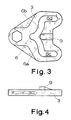
- FIG. 5 now shows an exemplary embodiment in which the switching body 11 is designed as a pivotable switching plate.
- the driver pin 5 of the spindle nut 2 is designed flat at its end 14 which engages in the link guide 13 of the switch body 11 of the position-reporting mechanism 12.
- the switching body 11 has an external toothing 15, the external toothing 15 meshes with a gear 16 and can be actuated with the aid of a position signaling shaft 17, not shown, connected to the gear 16 in a rotationally fixed manner.
- FIG. 6 shows an exemplary embodiment of a position-reporting mechanism 12 belonging to a swivel drive according to the invention, initially as a result is characterized in that the shift body 11 is designed as a shift drum rotatable about the longitudinal axis, the longitudinal axis of the shift body 11 running parallel to the longitudinal axis of the gear spindle 1.
- the driver pin 5 of the spindle nut 2 is circular in shape at its end 14 which engages in the link guide 13 of the switching body 11 of the position-reporting mechanism 12.
Landscapes
- Transmission Devices (AREA)
- Mechanisms For Operating Contacts (AREA)
- Switches With Compound Operations (AREA)
Applications Claiming Priority (2)
| Application Number | Priority Date | Filing Date | Title |
|---|---|---|---|
| DE4014150 | 1990-05-02 | ||
| DE4014150A DE4014150C2 (de) | 1990-05-02 | 1990-05-02 | Schwenkantrieb, insbesondere für Schaltgeräte |
Publications (2)
| Publication Number | Publication Date |
|---|---|
| EP0455039A1 true EP0455039A1 (fr) | 1991-11-06 |
| EP0455039B1 EP0455039B1 (fr) | 1996-01-10 |
Family
ID=6405609
Family Applications (1)
| Application Number | Title | Priority Date | Filing Date |
|---|---|---|---|
| EP91106015A Expired - Lifetime EP0455039B1 (fr) | 1990-05-02 | 1991-04-16 | Entraînement pivotant, en particulier pour appareils de commutation |
Country Status (3)
| Country | Link |
|---|---|
| EP (1) | EP0455039B1 (fr) |
| AT (1) | ATE133002T1 (fr) |
| DE (2) | DE4014150C2 (fr) |
Cited By (4)
| Publication number | Priority date | Publication date | Assignee | Title |
|---|---|---|---|---|
| FR2902572A1 (fr) * | 2006-06-14 | 2007-12-21 | Valeo Electronique Sys Liaison | Interrupteur a chemin de came comportant une rampe |
| FR2923099A1 (fr) * | 2007-10-29 | 2009-05-01 | Areva T & D Ag | Actionneur electromecanique muni d'un frein mecanique de type a ressort a spires enroule |
| FR2923074A1 (fr) * | 2007-10-29 | 2009-05-01 | Areva T & D Ag | Actionneur electromecanique et sectionneur haute ou moyenne tension muni d'un tel actionneur |
| CN101414514B (zh) * | 2008-11-24 | 2011-11-30 | 纪元电气集团有限公司 | 户内高压电动接地开关 |
Families Citing this family (1)
| Publication number | Priority date | Publication date | Assignee | Title |
|---|---|---|---|---|
| DE10205334C1 (de) * | 2002-02-06 | 2003-11-13 | Siemens Ag | Elektrische Schaltanordnung mit einem ersten Schaltkontakt und mit einem zweiten Schaltkondakt |
Citations (2)
| Publication number | Priority date | Publication date | Assignee | Title |
|---|---|---|---|---|
| CH479155A (de) * | 1967-11-24 | 1969-09-30 | Siemens Ag | Motorantrieb für einen elektrischen Schalter |
| EP0393557A2 (fr) * | 1989-04-21 | 1990-10-24 | Asea Brown Boveri Aktiengesellschaft | Commande de broches |
Family Cites Families (2)
| Publication number | Priority date | Publication date | Assignee | Title |
|---|---|---|---|---|
| DE191132C (fr) * | 1905-03-27 | |||
| AT248526B (de) * | 1964-05-27 | 1966-08-10 | Siemens Ag | Vorrichtung zur Stellungsmeldung für Trennschalter |
-
1990
- 1990-05-02 DE DE4014150A patent/DE4014150C2/de not_active Expired - Fee Related
-
1991
- 1991-04-16 AT AT91106015T patent/ATE133002T1/de not_active IP Right Cessation
- 1991-04-16 DE DE59107223T patent/DE59107223D1/de not_active Expired - Fee Related
- 1991-04-16 EP EP91106015A patent/EP0455039B1/fr not_active Expired - Lifetime
Patent Citations (2)
| Publication number | Priority date | Publication date | Assignee | Title |
|---|---|---|---|---|
| CH479155A (de) * | 1967-11-24 | 1969-09-30 | Siemens Ag | Motorantrieb für einen elektrischen Schalter |
| EP0393557A2 (fr) * | 1989-04-21 | 1990-10-24 | Asea Brown Boveri Aktiengesellschaft | Commande de broches |
Cited By (11)
| Publication number | Priority date | Publication date | Assignee | Title |
|---|---|---|---|---|
| FR2902572A1 (fr) * | 2006-06-14 | 2007-12-21 | Valeo Electronique Sys Liaison | Interrupteur a chemin de came comportant une rampe |
| FR2923099A1 (fr) * | 2007-10-29 | 2009-05-01 | Areva T & D Ag | Actionneur electromecanique muni d'un frein mecanique de type a ressort a spires enroule |
| FR2923074A1 (fr) * | 2007-10-29 | 2009-05-01 | Areva T & D Ag | Actionneur electromecanique et sectionneur haute ou moyenne tension muni d'un tel actionneur |
| CN101425402A (zh) * | 2007-10-29 | 2009-05-06 | 阿雷瓦T&D公司 | 机电致动器和具有这种致动器的高压或中压隔离开关 |
| EP2055980A1 (fr) | 2007-10-29 | 2009-05-06 | AREVA T&D AG | Actionneur électromécanique muni d'un frein mécanique de type à ressort à spires enroulé |
| EP2056313A1 (fr) | 2007-10-29 | 2009-05-06 | AREVA T&D AG | Actionneur électromécanique et sectionneur haute ou moyenne tension muni d'un tel actionneur |
| US7932794B2 (en) | 2007-10-29 | 2011-04-26 | Areva T&D Ag | Electro-mechanical actuator, and a high or medium voltage disconnector having such an actuator |
| US8356700B2 (en) | 2007-10-29 | 2013-01-22 | Areva T&O AG | Electro-mechanical actuator equipped with a mechanical brake of coil spring type |
| CN101425402B (zh) * | 2007-10-29 | 2013-04-24 | 阿雷瓦T&D公司 | 机电致动器和具有这种致动器的高压或中压隔离开关 |
| CN101425401B (zh) * | 2007-10-29 | 2013-11-13 | 阿尔斯通技术有限公司 | 装备有螺旋弹簧型机械制动器的电动机械致动器 |
| CN101414514B (zh) * | 2008-11-24 | 2011-11-30 | 纪元电气集团有限公司 | 户内高压电动接地开关 |
Also Published As
| Publication number | Publication date |
|---|---|
| DE59107223D1 (de) | 1996-02-22 |
| EP0455039B1 (fr) | 1996-01-10 |
| ATE133002T1 (de) | 1996-01-15 |
| DE4014150A1 (de) | 1991-11-14 |
| DE4014150C2 (de) | 1994-09-29 |
Similar Documents
| Publication | Publication Date | Title |
|---|---|---|
| DE19507952C2 (de) | Schaltvorrichtung | |
| EP3658799B1 (fr) | Dispositif de commutation comprenant un encliquetage magnétique | |
| DE102005062167B3 (de) | Schalthebel mit Betätigungseinrichtung für eine Rückwärtsgangsperre | |
| WO1988009451A1 (fr) | Console de changement de vitesses | |
| DE69304811T2 (de) | Schloss für die Tür eines Kraftfahrzeuges | |
| EP0455039B1 (fr) | Entraînement pivotant, en particulier pour appareils de commutation | |
| DE4420582C2 (de) | Einfahrbares Schaltgerät mit einer Anzeigevorrichtung für die Stellung des Schaltgerätes | |
| WO2024003660A1 (fr) | Appareil de commande électrique d'aiguillage | |
| DE4300313C1 (de) | Drehantrieb für kipphebelbetätigte Schaltgeräte und Verwendung hierfür | |
| EP1117950B1 (fr) | Dispositif de commutation pour boite automatique d'un vehicule a moteur | |
| DE1925962C3 (de) | Betätigungsvorrichtung für eine Fahrzeugschiebetür | |
| DE2923019C2 (de) | Hochspannungsschalter | |
| CH696476A5 (de) | Elektrische Schaltanordnung mit einem ersten Schaltkontakt und mit einem zweiten Schaltkontakt. | |
| DE4042374A1 (de) | Schwenkantrieb, insbesondere fuer schaltgeraete | |
| DE2216272C3 (de) | Hochspannungsschaltgerät, insbesondere Trennschalter | |
| DE10013107B4 (de) | Signaldurchgabevorrichtung | |
| EP0375732A1 (fr) | Dispositif de verrouillage pour appareil de coupure a commande electromagnetique | |
| DE3114727A1 (de) | Federantrieb fuer elektrische schaltgeraete | |
| EP0124751A2 (fr) | Commutateur de commande pour un dispositif de réglage de siège de véhicule | |
| DE69205503T2 (de) | Verbesserter Antriebsmechanismus für einen elektrischen Schalter, insbesondere Schutzschalter oder Leistungsschalter. | |
| DE3021802C2 (fr) | ||
| DE2832841C3 (de) | Zeitrelais mit elektromotorischem Antrieb | |
| DE1804456C3 (de) | Einrichtung zur zeilenweisen Abtastung der Oberfläche von Prüfobjekten | |
| DE3016324C2 (de) | Schaltvorrichtung zur Erzeugung einer hin- und hergehenden Schaltbewegung | |
| DE2740743A1 (de) | Getriebe fuer motorische zeitrelais |
Legal Events
| Date | Code | Title | Description |
|---|---|---|---|
| PUAI | Public reference made under article 153(3) epc to a published international application that has entered the european phase |
Free format text: ORIGINAL CODE: 0009012 |
|
| AK | Designated contracting states |
Kind code of ref document: A1 Designated state(s): AT CH DE GB LI NL SE |
|
| 17P | Request for examination filed |
Effective date: 19920109 |
|
| 17Q | First examination report despatched |
Effective date: 19931021 |
|
| GRAA | (expected) grant |
Free format text: ORIGINAL CODE: 0009210 |
|
| AK | Designated contracting states |
Kind code of ref document: B1 Designated state(s): AT CH DE GB LI NL SE |
|
| REF | Corresponds to: |
Ref document number: 133002 Country of ref document: AT Date of ref document: 19960115 Kind code of ref document: T |
|
| REF | Corresponds to: |
Ref document number: 59107223 Country of ref document: DE Date of ref document: 19960222 |
|
| GBT | Gb: translation of ep patent filed (gb section 77(6)(a)/1977) |
Effective date: 19960219 |
|
| PG25 | Lapsed in a contracting state [announced via postgrant information from national office to epo] |
Ref country code: SE Effective date: 19960410 |
|
| PG25 | Lapsed in a contracting state [announced via postgrant information from national office to epo] |
Ref country code: AT Effective date: 19960416 |
|
| PG25 | Lapsed in a contracting state [announced via postgrant information from national office to epo] |
Ref country code: LI Effective date: 19960430 Ref country code: CH Effective date: 19960430 |
|
| PLBE | No opposition filed within time limit |
Free format text: ORIGINAL CODE: 0009261 |
|
| STAA | Information on the status of an ep patent application or granted ep patent |
Free format text: STATUS: NO OPPOSITION FILED WITHIN TIME LIMIT |
|
| REG | Reference to a national code |
Ref country code: CH Ref legal event code: PL |
|
| 26N | No opposition filed | ||
| PGFP | Annual fee paid to national office [announced via postgrant information from national office to epo] |
Ref country code: GB Payment date: 19991012 Year of fee payment: 9 |
|
| PG25 | Lapsed in a contracting state [announced via postgrant information from national office to epo] |
Ref country code: GB Free format text: LAPSE BECAUSE OF NON-PAYMENT OF DUE FEES Effective date: 20000416 |
|
| GBPC | Gb: european patent ceased through non-payment of renewal fee |
Effective date: 20000416 |
|
| PGFP | Annual fee paid to national office [announced via postgrant information from national office to epo] |
Ref country code: DE Payment date: 20020514 Year of fee payment: 12 |
|
| PGFP | Annual fee paid to national office [announced via postgrant information from national office to epo] |
Ref country code: NL Payment date: 20020618 Year of fee payment: 12 |
|
| PG25 | Lapsed in a contracting state [announced via postgrant information from national office to epo] |
Ref country code: NL Free format text: LAPSE BECAUSE OF NON-PAYMENT OF DUE FEES Effective date: 20031101 Ref country code: DE Free format text: LAPSE BECAUSE OF NON-PAYMENT OF DUE FEES Effective date: 20031101 |
|
| NLV4 | Nl: lapsed or anulled due to non-payment of the annual fee |
Effective date: 20031101 |