EP0455061A1 - Mehrschichtwärmeschirm - Google Patents
Mehrschichtwärmeschirm Download PDFInfo
- Publication number
- EP0455061A1 EP0455061A1 EP19910106243 EP91106243A EP0455061A1 EP 0455061 A1 EP0455061 A1 EP 0455061A1 EP 19910106243 EP19910106243 EP 19910106243 EP 91106243 A EP91106243 A EP 91106243A EP 0455061 A1 EP0455061 A1 EP 0455061A1
- Authority
- EP
- European Patent Office
- Prior art keywords
- heat
- heat shield
- components
- component
- sheet material
- Prior art date
- Legal status (The legal status is an assumption and is not a legal conclusion. Google has not performed a legal analysis and makes no representation as to the accuracy of the status listed.)
- Withdrawn
Links
Images

Classifications
-
- B—PERFORMING OPERATIONS; TRANSPORTING
- B60—VEHICLES IN GENERAL
- B60R—VEHICLES, VEHICLE FITTINGS, OR VEHICLE PARTS, NOT OTHERWISE PROVIDED FOR
- B60R13/00—Elements for body-finishing, identifying, or decorating; Arrangements or adaptations for advertising purposes
- B60R13/08—Insulating elements, e.g. for sound insulation
-
- F—MECHANICAL ENGINEERING; LIGHTING; HEATING; WEAPONS; BLASTING
- F01—MACHINES OR ENGINES IN GENERAL; ENGINE PLANTS IN GENERAL; STEAM ENGINES
- F01N—GAS-FLOW SILENCERS OR EXHAUST APPARATUS FOR MACHINES OR ENGINES IN GENERAL; GAS-FLOW SILENCERS OR EXHAUST APPARATUS FOR INTERNAL-COMBUSTION ENGINES
- F01N13/00—Exhaust or silencing apparatus characterised by constructional features
- F01N13/14—Exhaust or silencing apparatus characterised by constructional features having thermal insulation
-
- B—PERFORMING OPERATIONS; TRANSPORTING
- B60—VEHICLES IN GENERAL
- B60K—ARRANGEMENT OR MOUNTING OF PROPULSION UNITS OR OF TRANSMISSIONS IN VEHICLES; ARRANGEMENT OR MOUNTING OF PLURAL DIVERSE PRIME-MOVERS IN VEHICLES; AUXILIARY DRIVES FOR VEHICLES; INSTRUMENTATION OR DASHBOARDS FOR VEHICLES; ARRANGEMENTS IN CONNECTION WITH COOLING, AIR INTAKE, GAS EXHAUST OR FUEL SUPPLY OF PROPULSION UNITS IN VEHICLES
- B60K13/00—Arrangement in connection with combustion air intake or gas exhaust of propulsion units
- B60K13/04—Arrangement in connection with combustion air intake or gas exhaust of propulsion units concerning exhaust
-
- F—MECHANICAL ENGINEERING; LIGHTING; HEATING; WEAPONS; BLASTING
- F16—ENGINEERING ELEMENTS AND UNITS; GENERAL MEASURES FOR PRODUCING AND MAINTAINING EFFECTIVE FUNCTIONING OF MACHINES OR INSTALLATIONS; THERMAL INSULATION IN GENERAL
- F16L—PIPES; JOINTS OR FITTINGS FOR PIPES; SUPPORTS FOR PIPES, CABLES OR PROTECTIVE TUBING; MEANS FOR THERMAL INSULATION IN GENERAL
- F16L59/00—Thermal insulation in general
- F16L59/08—Means for preventing radiation, e.g. with metal foil
-
- Y—GENERAL TAGGING OF NEW TECHNOLOGICAL DEVELOPMENTS; GENERAL TAGGING OF CROSS-SECTIONAL TECHNOLOGIES SPANNING OVER SEVERAL SECTIONS OF THE IPC; TECHNICAL SUBJECTS COVERED BY FORMER USPC CROSS-REFERENCE ART COLLECTIONS [XRACs] AND DIGESTS
- Y10—TECHNICAL SUBJECTS COVERED BY FORMER USPC
- Y10S—TECHNICAL SUBJECTS COVERED BY FORMER USPC CROSS-REFERENCE ART COLLECTIONS [XRACs] AND DIGESTS
- Y10S428/00—Stock material or miscellaneous articles
- Y10S428/913—Material designed to be responsive to temperature, light, moisture
-
- Y—GENERAL TAGGING OF NEW TECHNOLOGICAL DEVELOPMENTS; GENERAL TAGGING OF CROSS-SECTIONAL TECHNOLOGIES SPANNING OVER SEVERAL SECTIONS OF THE IPC; TECHNICAL SUBJECTS COVERED BY FORMER USPC CROSS-REFERENCE ART COLLECTIONS [XRACs] AND DIGESTS
- Y10—TECHNICAL SUBJECTS COVERED BY FORMER USPC
- Y10T—TECHNICAL SUBJECTS COVERED BY FORMER US CLASSIFICATION
- Y10T428/00—Stock material or miscellaneous articles
- Y10T428/24—Structurally defined web or sheet [e.g., overall dimension, etc.]
- Y10T428/24777—Edge feature
-
- Y—GENERAL TAGGING OF NEW TECHNOLOGICAL DEVELOPMENTS; GENERAL TAGGING OF CROSS-SECTIONAL TECHNOLOGIES SPANNING OVER SEVERAL SECTIONS OF THE IPC; TECHNICAL SUBJECTS COVERED BY FORMER USPC CROSS-REFERENCE ART COLLECTIONS [XRACs] AND DIGESTS
- Y10—TECHNICAL SUBJECTS COVERED BY FORMER USPC
- Y10T—TECHNICAL SUBJECTS COVERED BY FORMER US CLASSIFICATION
- Y10T428/00—Stock material or miscellaneous articles
- Y10T428/24—Structurally defined web or sheet [e.g., overall dimension, etc.]
- Y10T428/24942—Structurally defined web or sheet [e.g., overall dimension, etc.] including components having same physical characteristic in differing degree
-
- Y—GENERAL TAGGING OF NEW TECHNOLOGICAL DEVELOPMENTS; GENERAL TAGGING OF CROSS-SECTIONAL TECHNOLOGIES SPANNING OVER SEVERAL SECTIONS OF THE IPC; TECHNICAL SUBJECTS COVERED BY FORMER USPC CROSS-REFERENCE ART COLLECTIONS [XRACs] AND DIGESTS
- Y10—TECHNICAL SUBJECTS COVERED BY FORMER USPC
- Y10T—TECHNICAL SUBJECTS COVERED BY FORMER US CLASSIFICATION
- Y10T428/00—Stock material or miscellaneous articles
- Y10T428/31504—Composite [nonstructural laminate]
- Y10T428/31678—Of metal
Definitions
- the present invention relates to a multi-component heat shield. More particularly, the present invention provides a multi-component heat shield for use in a motor vehicle.
- the exhaust systems currently found in motor vehicles such as car, vans and light trucks typically include a number of elements designed to operate at elevated temperatures.
- Devices such as catalytic converters, mufflers and portions of the exhaust system piping commonly reach temperatures well over 80 ⁇ 0 ⁇ o F during normal vehicle operation.
- the temperature of a catalytic converter may exceed 120 ⁇ 0 ⁇ o F during prolonged periods of motor idling.
- an object of the present invention to provide an inexpensive, light weight heat shield which will effectively reduce the heat transmitted from a vehicle's exhaust system to its passenger and storage compartments.
- the present invention meets the above-stated objectives by providing a multi-component heat shield including a first component having a first surface and a second heat insulating component having a second surface and an opposite surface.
- the materials comprising the first and second components are selected so that the components have different coefficients of thermal expansion.
- the components are arranged so that at least a portion of the first surface is in registration with at least a portion of the second surface over a given common area.
- Means are provided so that as heat is applied to the shield movement of the components relative to one another is restrained at selected positions.
- the components are free to move relative to one another between the selected positions so that differences in the lengths of the first and second components between the selected positions due to changes in the temperatures of the components are accompanied by an increase in the spacing between the first and second surfaces. It is believed that the improved insulating capacity of the heat shield results in large part from the increase in the spacing between the portions of the first and second surfaces.
- the first component is a heat reflecting component having a coefficient of thermal expansion greater than that of the heat insulating component.
- the first component need not have a coefficient of thermal expansion greater than that of the insulating component, and, in fact, the present invention contemplates a heat shield having a first component which is heat absorbing.
- the heat shield is mounted on a motor vehicle between the heat emitting elements of the vehicle's exhaust system and its passenger or storage compartments.
- the shield is mounted with the opposite surface of the heat insulating component attached adjacent to the underside of the vehicle's floor.
- the first component which in this application is heat reflecting and has a higher coefficient of thermal expansion than the shield's heat insulating component, moves away from the insulating component and toward the heat source with a resulting increase in the insulating capacity of the shield.
- Fig. 1 is a cross-sectional view of a heat shield as taught by the present invention.
- Fig. 2 is a cross-sectional view of the heat shield of claim 1 when subjected to heating.
- Fig. 3 is an exploded perspective view of the heat shield shown in Fig. 1.
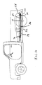
- Fig. 4 is a somewhat schematic representation of the heat shield of claim 1 mounted on a motor vehicle.
- Fig. 1 illustrates a preferred embodiment of the heat shield taught by the present invention.
- the heat shield 10 ⁇ comprises a heat insulating component 12, a heat reflecting component 14 and a bead of adhesive 16 rigidly connecting the reflecting and insulating components.
- the materials comprising the components are selected so that the heat insulating component has a lower coefficient of thermal expansion than the heat reflecting component.
- the insulating component 12 may be formed from any rigid material which provides the required insulating properties. Rigid sheet materials are particularly useful in this regard such as, for example, thermoset, thermoplastic and fiber-reinforced composite sheet materials.
- the insulating component comprises a rigid, thermoset, sheet material.
- the thermoset sheet material is a phenolic sheet molding compound such as, for example, "LYTHERM 10 ⁇ 0 ⁇ 0 ⁇ ” available from Lydall, Inc., Manchester, CT.
- the "LYTHERM” sheet comprising the insulating component 12 preferably has a thermal conductivity of less than 0 ⁇ .3 W/mK and a coefficient of thermal expansion of about 3 x 10 ⁇ 6/ o F.
- the sheet is moulded to a density of approximately 1.2g/cc and a thickness of about 2-3mm.
- the "LYTHERM” sheet is fully cured and the surfaces 18, 20 of the insulating component are coated with a heat resistant and heat reflective material such as, for example, aluminum foil or a heat resistant and heat reflective paint.
- the surfaces 18, 20 are painted with "LO/MIT-1", a radiant barrier, low emissivity coating available from Solar Energy Corp., Princeton, NJ.
- the heat reflecting component 14 comprises any suitable material having the ability to reflect infrared radiation.
- the reflecting component is formed from a metallic sheet material.
- the reflecting component 14 is formed from aluminum sheet stock which has a thickness of about 0 ⁇ .0 ⁇ 18 inches and a coefficient of thermal expansion of about 1.224 x 10 ⁇ ⁇ 5/ o F.
- the aluminum sheet stock is manufactured so that the surfaces 22, 24 of component 14 have a soft temper, mill finish.
- Aluminum sheet stock meeting these requirements are available from, for example, DIY Aluminum, Oaklahoma City, Oaklahoma (Stock #0 ⁇ 60 ⁇ 1), Eastern Aluminum Sheet and Extrusion Company, Richmond, Virginia (Stock #1120 ⁇ ) and Metal Foils, Inc., Wickliffe, Ohio (Stock QQ-A-250 ⁇ /1).
- the shield 10 ⁇ is assembled so that at least a portion of surface 20 ⁇ is in registration with at least a portion of surface 24 over a common area.
- the surfaces 20 ⁇ and 24 are co-extensive.
- the invention is not limited in this regard, and a shield constructed with reflecting and insulating components having dissimilar surface areas are within the scope of the appended claims.
- Means are provided to restrict the movement of components 12 and 14 at selected positions. In the most preferred embodiment of the invention this is accomplished by rigidly connecting the heat reflecting component to the heat insulating component at selected contact positions along the perimeter of the common area such as, for example, by applying a bead of adhesive 16 along the entire perimeter.
- Silicone caulk adhesives are particularly useful for this purpose such as, for example, silicone caulk adhesive, Construction Stock No. SCS 10 ⁇ 0 ⁇ 1, available from the General Electric Co., Waterford, NY.
- the components could be connected by fasteners such as rivets, screws, clips or bolts placed along the perimeter of the common area.
- the location of the selected positions at which the components are rigidly connected together may vary widely as long as a common area between the selected positions is provided over which at least a portion of surfaces 20 ⁇ and 24 are in registration.
- the components 12 and 14 need not be connected together at all; a separate mounting member may be provided which rigidly supports each component in a desired position relative to the other.
- the shield 10 ⁇ is assembled with the surfaces 20 and 24 in spaced relationship.
- the space 26 between the heat reflecting and heat insulating components is from about 0 ⁇ .0 ⁇ 31 inches to about 0 ⁇ .0 ⁇ 93 inches.
- the thickness of the adhesive bead 16 is adjusted to provide the desired spacing. If fasteners such as rivets or screws are employed, washers are provided to provide the proper spacing.
- the shield be assembled with the space 16 between the surfaces 20 ⁇ and 24. This is a preferred embodiment of the invention only, and the invention contemplates a shield wherein the reflecting and insulating components are assembled with surface 20 ⁇ adjacent to and in contact with surface 24.
- Figs. 1 and 2 it will readily be understood that with the shield assembled in the manner illustrated in Fig. 1, the components 12 and 14 are restrained from movement relative to one another at the perimeter of the common area; however, the components are free to move relative to each other within this area.
- the heat reflecting component 14 tends to expand at a greater rate, due to its higher coefficient of thermal expansion, than the heat insulating component 12. But, since the components are rigidly connected at the perimeter of the common area, the reflecting component cannot simply expand relative to the insulating component in a direction parallel to surfaces 20 ⁇ and 24.
- reflecting component 14 tends to bow away from the insulating component 14 and assume the configuration illustrated in Fig. 2.
- Fig. 4 illustrates the heat shield 10 ⁇ disposed between the bed 28 of a typical light duty pick-up truck and a portion of the truck's exhaust system including pipes 30 ⁇ and muffler 32.
- the exhaust pipes 30 ⁇ reach temperatures above 80 ⁇ 0 ⁇ o F and pass within a few inches of the lower surface 34 of the bed 28.
- the temperature of the muffler itself may exceed 10 ⁇ 0 ⁇ 0 ⁇ o F.
- the heat shield 10 ⁇ is attached adjacent to the lower surface 34 of the bed 28. This may be accomplished by any suitable fastening means but is preferably accomplished by adhesively attaching or screwing the heat shield 10 ⁇ to the frame 36 which supports the bed 28.
- the space 26 between the reflecting and insulating components minimizes the amount of heat flowing via conduction from the reflecting component 14 to the insulating component 12.
- the insulating effect of the space, and the shield as a whole is greatly enhanced as the shield is heated and the reflecting component bows away from the insulating component to increase the space between surfaces 20 ⁇ and 24.
- the heat resistant and reflective paint or foil on the surface 20 ⁇ of the insulating component reflects some of the incident infrared radiation back to the reflecting component 14.
- the low thermal conductivity of the insulating component minimizes the conduction of the small amount of heat energy absorbed by the component, and the coating on surface 18 emits infrared energy at only a very low rate to the bed 26.
Landscapes
- Engineering & Computer Science (AREA)
- Mechanical Engineering (AREA)
- General Engineering & Computer Science (AREA)
- Chemical & Material Sciences (AREA)
- Combustion & Propulsion (AREA)
- Transportation (AREA)
- Physics & Mathematics (AREA)
- Acoustics & Sound (AREA)
- Laminated Bodies (AREA)
- Body Structure For Vehicles (AREA)
- Vehicle Interior And Exterior Ornaments, Soundproofing, And Insulation (AREA)
- Thermal Insulation (AREA)
Applications Claiming Priority (2)
| Application Number | Priority Date | Filing Date | Title |
|---|---|---|---|
| US07/516,205 US5108817A (en) | 1990-04-30 | 1990-04-30 | Multi-component heat shield |
| US516205 | 1990-04-30 |
Publications (1)
| Publication Number | Publication Date |
|---|---|
| EP0455061A1 true EP0455061A1 (de) | 1991-11-06 |
Family
ID=24054582
Family Applications (1)
| Application Number | Title | Priority Date | Filing Date |
|---|---|---|---|
| EP19910106243 Withdrawn EP0455061A1 (de) | 1990-04-30 | 1991-04-18 | Mehrschichtwärmeschirm |
Country Status (5)
| Country | Link |
|---|---|
| US (1) | US5108817A (de) |
| EP (1) | EP0455061A1 (de) |
| JP (1) | JPH0659704B2 (de) |
| KR (1) | KR910018236A (de) |
| CA (1) | CA2041335A1 (de) |
Cited By (5)
| Publication number | Priority date | Publication date | Assignee | Title |
|---|---|---|---|---|
| EP0934809A1 (de) | 1998-02-05 | 1999-08-11 | H. Weidmann AG | Hitzeschild für ein Kraftfahrzeug |
| EP0751044B1 (de) * | 1995-06-27 | 1999-12-29 | TBA Composites Inc | Laminierter Hitzeschild |
| EP1129277A4 (de) * | 1998-10-12 | 2002-01-23 | Nu Chem Inc | Isolationsschild, insbesondere für fahrzeug-abgassysteme |
| WO2008096262A1 (en) * | 2007-02-09 | 2008-08-14 | Porcher Industries | Laminated thermal insulating material comprising a silicone-based adhesive |
| US10974783B2 (en) * | 2018-08-17 | 2021-04-13 | Harley-Davidson Motor Company Group, LLC | Exhaust shield assembly |
Families Citing this family (17)
| Publication number | Priority date | Publication date | Assignee | Title |
|---|---|---|---|---|
| ATE94811T1 (de) | 1990-01-22 | 1993-10-15 | Atd Corp | Kissenartig geformtes gebilde mit waermeleitzonen und thermischen isolierzonen und verformbares laminat. |
| GB9407107D0 (en) * | 1994-04-11 | 1994-06-01 | Colebrand Ltd | A cover |
| DE4429104A1 (de) * | 1994-08-17 | 1996-02-22 | Pirchl Gerhard | Verfahren zur Herstellung eines Hitzeschildes und Hitzeschild, welches nach dem Verfahren hergestellt ist |
| DE19721796A1 (de) * | 1997-05-24 | 1998-12-03 | Audi Ag | Kraftfahrzeugbauteil |
| JP3531816B2 (ja) * | 2001-06-06 | 2004-05-31 | 本田技研工業株式会社 | 車両フロアの遮熱装置 |
| US6647715B2 (en) | 2001-11-30 | 2003-11-18 | Van-Rob Stampings Inc. | Heat shield for an exhaust system of an internal combustion engine |
| EP1469939A1 (de) * | 2002-01-29 | 2004-10-27 | Cabot Corporation | Hitzebeständiger aerogelenthaltender isolierungsverbundstoff, zusammensetzung zur herstellung von aerogelen und verfahren zur herstellung von dem isolierungsverbundstoff |
| RU2303744C2 (ru) * | 2002-05-15 | 2007-07-27 | Кабот Корпорейшн | Жаростойкий изоляционный композитный материал и способ его получения |
| US20040202807A1 (en) * | 2003-04-09 | 2004-10-14 | Earnest Robert D. | Insulated material and articles made therefrom |
| US7150485B2 (en) * | 2004-06-17 | 2006-12-19 | Freudenberg-Nok General Partnership | Mold-integrated heat shield |
| US20070098954A1 (en) * | 2005-11-01 | 2007-05-03 | Kozerski Richard J | Plastic/metal hybrid engine shield |
| US8349438B2 (en) * | 2008-01-03 | 2013-01-08 | The Boeing Company | Insulative material and associated method of forming same |
| US8056953B2 (en) * | 2008-06-13 | 2011-11-15 | Itt Manufacturing Enterprises, Inc. | Thermal barrier system |
| GB2480494B (en) * | 2010-05-21 | 2017-03-15 | Gm Global Tech Operations Llc | Heat protection for load bearing component |
| US8635860B1 (en) | 2011-02-02 | 2014-01-28 | Ralph P. Robinson | Internal combustion engine heat transfer system |
| US9151255B2 (en) | 2011-09-23 | 2015-10-06 | Carter Fuel Systems, Llc | Marine fuel system with spill control feature |
| US8925670B2 (en) * | 2013-02-14 | 2015-01-06 | Yamaha Hatsudoki Kabushiki Kaisha | Vehicle |
Citations (4)
| Publication number | Priority date | Publication date | Assignee | Title |
|---|---|---|---|---|
| DE1214711B (de) * | 1956-07-16 | 1966-04-21 | Union Carbide Corp | Waermeisolierter Behaelter |
| DE2819371A1 (de) * | 1978-05-03 | 1979-11-08 | Volkswagenwerk Ag | Waermeschirm fuer eine abgasanlage eines fahrzeugs |
| GB2196097A (en) * | 1986-10-03 | 1988-04-20 | Nat Nuclear Corp Ltd | Thermal insulation |
| DE3825520A1 (de) * | 1988-07-27 | 1990-02-01 | Siemens Ag | Waermedaemmkoerper |
Family Cites Families (12)
| Publication number | Priority date | Publication date | Assignee | Title |
|---|---|---|---|---|
| US3244224A (en) * | 1961-12-18 | 1966-04-05 | Nat Res Corp | Space vehicle insulation |
| BE635030A (de) * | 1962-07-20 | |||
| FR2166542A5 (de) * | 1971-12-29 | 1973-08-17 | Bronzavia Sa | |
| US3756623A (en) * | 1972-08-28 | 1973-09-04 | L Whittler | Heat shield for a motorcycle |
| JPS51116323A (en) * | 1975-04-04 | 1976-10-13 | Nissan Motor Co Ltd | Heat shading device of exhaust system |
| JPS5258323U (de) * | 1975-10-27 | 1977-04-27 | ||
| JPS594818Y2 (ja) * | 1979-07-16 | 1984-02-13 | 本田技研工業株式会社 | 発熱部の車体への支持装置 |
| US4344591A (en) * | 1979-09-05 | 1982-08-17 | The United States Of America Asrepresented By The Administrator Of The National Aeronautics And Space Administration | Multiwall thermal protection system |
| US4508771A (en) * | 1979-11-19 | 1985-04-02 | Exxon Research & Engineering Co. | Extruded carpet backing with resin and elastomer components |
| US4433542A (en) * | 1982-07-22 | 1984-02-28 | Nissan Motor Company, Limited | Heat-shielding structure |
| US4478310A (en) * | 1983-03-25 | 1984-10-23 | Apx Group, Inc. | Universal heat shield |
| US4741411A (en) * | 1987-01-14 | 1988-05-03 | Deere & Company | Muffler system |
-
1990
- 1990-04-30 US US07/516,205 patent/US5108817A/en not_active Expired - Fee Related
-
1991
- 1991-04-18 EP EP19910106243 patent/EP0455061A1/de not_active Withdrawn
- 1991-04-26 CA CA 2041335 patent/CA2041335A1/en not_active Abandoned
- 1991-04-29 KR KR1019910006852A patent/KR910018236A/ko not_active Withdrawn
- 1991-04-30 JP JP9886791A patent/JPH0659704B2/ja not_active Expired - Lifetime
Patent Citations (4)
| Publication number | Priority date | Publication date | Assignee | Title |
|---|---|---|---|---|
| DE1214711B (de) * | 1956-07-16 | 1966-04-21 | Union Carbide Corp | Waermeisolierter Behaelter |
| DE2819371A1 (de) * | 1978-05-03 | 1979-11-08 | Volkswagenwerk Ag | Waermeschirm fuer eine abgasanlage eines fahrzeugs |
| GB2196097A (en) * | 1986-10-03 | 1988-04-20 | Nat Nuclear Corp Ltd | Thermal insulation |
| DE3825520A1 (de) * | 1988-07-27 | 1990-02-01 | Siemens Ag | Waermedaemmkoerper |
Cited By (6)
| Publication number | Priority date | Publication date | Assignee | Title |
|---|---|---|---|---|
| EP0751044B1 (de) * | 1995-06-27 | 1999-12-29 | TBA Composites Inc | Laminierter Hitzeschild |
| EP0934809A1 (de) | 1998-02-05 | 1999-08-11 | H. Weidmann AG | Hitzeschild für ein Kraftfahrzeug |
| EP1129277A4 (de) * | 1998-10-12 | 2002-01-23 | Nu Chem Inc | Isolationsschild, insbesondere für fahrzeug-abgassysteme |
| WO2008096262A1 (en) * | 2007-02-09 | 2008-08-14 | Porcher Industries | Laminated thermal insulating material comprising a silicone-based adhesive |
| FR2912489A1 (fr) * | 2007-02-09 | 2008-08-15 | Porcher Ind Sa | Materiau isolant thermique multicouche comprenant un adhesif a base de silicone. |
| US10974783B2 (en) * | 2018-08-17 | 2021-04-13 | Harley-Davidson Motor Company Group, LLC | Exhaust shield assembly |
Also Published As
| Publication number | Publication date |
|---|---|
| CA2041335A1 (en) | 1991-10-31 |
| JPH0659704B2 (ja) | 1994-08-10 |
| JPH04229245A (ja) | 1992-08-18 |
| US5108817A (en) | 1992-04-28 |
| KR910018236A (ko) | 1991-11-30 |
Similar Documents
| Publication | Publication Date | Title |
|---|---|---|
| EP0455061A1 (de) | Mehrschichtwärmeschirm | |
| US5996730A (en) | Heat shield with acoustic insulation | |
| US5658652A (en) | Panel structure for vehicles | |
| US5656353A (en) | Laminated heat shield with prongs and method of manufacturing same | |
| US5844177A (en) | Heat shield with fastening for exhaust systems | |
| US6335073B1 (en) | Thermal shield for components made of thermoplastics | |
| US20140265413A1 (en) | Three-layer acoustic insulator | |
| HU214078B (en) | Vehicle wheel | |
| US8056613B2 (en) | Vehicle including heat guard for control module | |
| US5803524A (en) | Sidewall protection panel with expansion accommodating members | |
| JP4135609B2 (ja) | 自動車用の熱機能構造体 | |
| JPS6223874A (ja) | 自動車の樹脂製外板パネルの取り付け構造 | |
| GB2270555A (en) | Heat shields | |
| US20040012219A1 (en) | Multi-functional passenger compartment shield | |
| EP1433661A2 (de) | Struktur einer Seitenwand einer Fahrzeugkarosserie | |
| JP3678013B2 (ja) | 車両の内装材の取り付け方法および内装構造 | |
| US20180315411A1 (en) | Acoustic material | |
| JPS6319255Y2 (de) | ||
| US20060226585A1 (en) | Air spring suspension system | |
| CA2305343A1 (en) | Protective bar for vehicle door | |
| CN109941208A (zh) | 一种汽车发动机隔热消音铝罩 | |
| JP4534874B2 (ja) | 車両用内装部材の放熱構造 | |
| JPS6340352Y2 (de) | ||
| AU2006101048B4 (en) | Multi-Layered Heat Shield | |
| JPH0445950Y2 (de) |
Legal Events
| Date | Code | Title | Description |
|---|---|---|---|
| PUAI | Public reference made under article 153(3) epc to a published international application that has entered the european phase |
Free format text: ORIGINAL CODE: 0009012 |
|
| AK | Designated contracting states |
Kind code of ref document: A1 Designated state(s): DE FR GB IT SE |
|
| 17P | Request for examination filed |
Effective date: 19920228 |
|
| 17Q | First examination report despatched |
Effective date: 19920225 |
|
| STAA | Information on the status of an ep patent application or granted ep patent |
Free format text: STATUS: THE APPLICATION IS DEEMED TO BE WITHDRAWN |
|
| 18D | Application deemed to be withdrawn |
Effective date: 19930427 |