EP0455074A1 - Klappträger, insbesondere zum Tragen von Fahrrädern - Google Patents
Klappträger, insbesondere zum Tragen von Fahrrädern Download PDFInfo
- Publication number
- EP0455074A1 EP0455074A1 EP91106373A EP91106373A EP0455074A1 EP 0455074 A1 EP0455074 A1 EP 0455074A1 EP 91106373 A EP91106373 A EP 91106373A EP 91106373 A EP91106373 A EP 91106373A EP 0455074 A1 EP0455074 A1 EP 0455074A1
- Authority
- EP
- European Patent Office
- Prior art keywords
- bicycles
- upsetable
- arm
- fitted
- fact
- Prior art date
- Legal status (The legal status is an assumption and is not a legal conclusion. Google has not performed a legal analysis and makes no representation as to the accuracy of the status listed.)
- Withdrawn
Links
- 230000000284 resting effect Effects 0.000 claims description 14
- 230000000903 blocking effect Effects 0.000 claims description 13
- 230000002829 reductive effect Effects 0.000 claims description 5
- 238000009434 installation Methods 0.000 claims 1
- 230000033001 locomotion Effects 0.000 description 2
- 230000000717 retained effect Effects 0.000 description 2
- XAGFODPZIPBFFR-UHFFFAOYSA-N aluminium Chemical compound [Al] XAGFODPZIPBFFR-UHFFFAOYSA-N 0.000 description 1
- 229910052782 aluminium Inorganic materials 0.000 description 1
- 239000004411 aluminium Substances 0.000 description 1
- 238000010276 construction Methods 0.000 description 1
- 230000000670 limiting effect Effects 0.000 description 1
- 230000036961 partial effect Effects 0.000 description 1
- 230000002040 relaxant effect Effects 0.000 description 1
Images




Classifications
-
- B—PERFORMING OPERATIONS; TRANSPORTING
- B60—VEHICLES IN GENERAL
- B60R—VEHICLES, VEHICLE FITTINGS, OR VEHICLE PARTS, NOT OTHERWISE PROVIDED FOR
- B60R9/00—Supplementary fittings on vehicle exterior for carrying loads, e.g. luggage, sports gear or the like
- B60R9/06—Supplementary fittings on vehicle exterior for carrying loads, e.g. luggage, sports gear or the like at vehicle front or rear
-
- B—PERFORMING OPERATIONS; TRANSPORTING
- B60—VEHICLES IN GENERAL
- B60R—VEHICLES, VEHICLE FITTINGS, OR VEHICLE PARTS, NOT OTHERWISE PROVIDED FOR
- B60R9/00—Supplementary fittings on vehicle exterior for carrying loads, e.g. luggage, sports gear or the like
- B60R9/08—Supplementary fittings on vehicle exterior for carrying loads, e.g. luggage, sports gear or the like specially adapted for sports gear
- B60R9/10—Supplementary fittings on vehicle exterior for carrying loads, e.g. luggage, sports gear or the like specially adapted for sports gear for cycles
Definitions
- the present invention concerns one pliable device for carrying bicycles, suited for being mounted on recreational vehicles as campers, motorhomes, motorcaravans and caravans.
- the transportation of the auxiliary means of locomotion is done through some supporting devices, which are mounted outside the cockpit, solution that offers the advantage of not using the reduced space availability inside the room.
- the partially pliable kind including one frame fitted with some brackets for fixing it at one cockpit wall, and to which one shelf and one arm, upsetable from a working position to a resting position, are constrained, the shelf being fitted with rails for the lodging of the bicycles weels and with belts for fixing the weels, the arms being fitted with belts for the fixing of the bicycles barrels.
- Purpose of present invention is a pliable device for carrying bicycles, which allows to overcome the disadvantages of the known solutions, and that in working position, but especially in resting position, has a minimal extension in height.
- the device as to the invention includes one frame fitted with wall fixing brackets and to which one shelf and one arm, upsetable from a working to a resting position, are constrained, the shelf being fitted with at least one rail for the lodging of the bicycles weels and of belts for blocking the same, the arm being fitted with belts for blocking the bicycles barrels, the device being characterized from the fact that said frame is composed from a fixed structure and from a structure moveable from a working to a resting position.
- said moveable structure is upsetable and formed from one U-shaped tube, pivoted to the fixed structure through pins and fixable to the same in working position, through disengageable blocking means.
- said upsetable structure is constrained to one end of the fixed structure, in a way that it sticks out in spurts in working position and receds inside in resting position; furtherly said fixed structure can be hanged and unhanged from said wall through mounting brackets, situated at a reduced distance, inferior to the height of the bicycles and said upsetable arm is constrained to said upsetable structure.
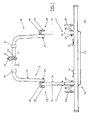
- Device 10 includes one frame, indicated with no. 12, composed from one fixed structure no. 13 and one moveable structure no. 14, in particular one upsetable structure, made for in. in anodyzed aluminium.
- the fixed structure 13 is of tubular kind, made up from two U-shaped backboards 15, which are linked from a crosspiece, not showed, which is fitted with journal boxes 16 for the bearing to the wall 11; each backboard 15 has adjustable height, being formed from two pieces engaged in one other and fixed with through bolts 17.
- the backboards 15 are fitted with lower - 16 - and upper - 18 - attachments brackets, situated at a distance inferior to the height of the bicycles, through which the device 10 can be hanged and unhanged from the wall 11.
- the shelf 19 is formed from one U-shaped tube, indicated with no. 23, to which three rails 24 are fixed, being these rails fitted with belts 25 for blocking the bicycles weels.
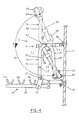
- the upsetable structure 14 is formed from one U-shaped tube 26, which is pivoted to the fixed structure 13 through two bolts 27, which act as fulcrum, and which is fixable through means log blocking 28, visible also in pict. 6, made up from one threaded spindle fitted with one chagreened handle 29, passing through some holes of the tubes 15 and 26, such as the one indicated as no. 39 in pictures 4 and 5, and from one nut, or wing nut, 30; as an alternative, the blocking means 28 could be made up from one nail, passing through holes of the tubes 15 and 26, and kept in seat from one proper spring (not showed).
- Some sleeves 31 are mounted on the tube 26, two as support for the bicycles, and one as support of the upsetable arm 32, which is blocked on same tube 26 through the bracket 33, fitted with threaded ends, and through the wing nuts 34.
- the arm 32 is fitted with sleeves 35, belts 36 and from one blocking terminal belt 37, fixed to same arm.
- the device 10 can be mounted on wall 11 in one area of modest height, for in. below one window, because the distance between the attachment brackets 16 and 18 is reduced, inferior to the bicycles height.
- the upsetable shelf 19 is opened and substantially put in orthogonal position in relation to the tubolar structure 13, retained firmly from selfblocking holdfasts 22; the tubolar upsetable structure 14 is lifted and fixed in spurts in relation to the structure 13, substantially parallel to the wall 11, through the blocking brackets 28; the upsetable arm 32 is opened and put orthogonally, or inclined of a definite corner, in relation to the structure 14.
- the bicycles are put on the shelf 19, with the weels positioned in the rails 24 fixed through the belts 25 and with their barrels fixed to the arm 32 through the belts 36.
- the arm 32 can be bent again, by rotating it of a corner of about 115°, as showed from the arch 40 in picture 3, first by relaxing, and then by blocking again, the wing nuts 34 end the bracket 33; the tubolar structure 14 can be lowered, by rotating it of a corner of about 185°, as showed from arch 41 in picture 4, for positioning it inside the backboards 15 of the fixed structure 13, removing the blocking means 28 from the holes 39; finally, the shelf 19 can be lifted, by rotating it of a corner of about 90°, as showed from arch 43 in picture 5, after detaching the holdfasts 22 from the backboards 15, in a way to upset it next to the structure 13, to which it is fixed through belts, as the one showed with no. 38 in same picture 5.
- the structures 13 and 14 are retained firmly in resting position from the tube 26 which inserts itself in one roll 24, as shown in picture 5; if necessary, it can even be used one belt 36 for blocking the structure 14 with respect to the structure 13.
- the device 10 is particularly functional as it is very manegeable and very easy to be operated, and as for the little encumbrance in height, which is extremely reduced, especially in resting position, as shown in picture 5; it can be therefore mounted on the wall 11 even below an eventual window, because it will obstruct this only partially in working position, whilst the window is completely free in resting position.
Landscapes
- Engineering & Computer Science (AREA)
- Mechanical Engineering (AREA)
- Motorcycle And Bicycle Frame (AREA)
- Fittings On The Vehicle Exterior For Carrying Loads, And Devices For Holding Or Mounting Articles (AREA)
Applications Claiming Priority (2)
| Application Number | Priority Date | Filing Date | Title |
|---|---|---|---|
| IT20073A IT1239907B (it) | 1990-04-19 | 1990-04-19 | Dispositivo porta-biciclette pieghevole |
| IT2007390 | 1990-04-19 |
Publications (1)
| Publication Number | Publication Date |
|---|---|
| EP0455074A1 true EP0455074A1 (de) | 1991-11-06 |
Family
ID=11163586
Family Applications (1)
| Application Number | Title | Priority Date | Filing Date |
|---|---|---|---|
| EP91106373A Withdrawn EP0455074A1 (de) | 1990-04-19 | 1991-04-19 | Klappträger, insbesondere zum Tragen von Fahrrädern |
Country Status (2)
| Country | Link |
|---|---|
| EP (1) | EP0455074A1 (de) |
| IT (1) | IT1239907B (de) |
Citations (2)
| Publication number | Priority date | Publication date | Assignee | Title |
|---|---|---|---|---|
| DE3235248A1 (de) * | 1982-09-23 | 1984-03-29 | Hymer-Leichtmetallbau, 7988 Wangen | Heckgepaecktraeger mit fahrradhalter fuer wohnmobile und dergleichen |
| EP0362082A1 (de) * | 1988-09-13 | 1990-04-04 | James Fiol | Gepäckträger für Wohnmobile und dergleichen |
-
1990
- 1990-04-19 IT IT20073A patent/IT1239907B/it active IP Right Grant
-
1991
- 1991-04-19 EP EP91106373A patent/EP0455074A1/de not_active Withdrawn
Patent Citations (2)
| Publication number | Priority date | Publication date | Assignee | Title |
|---|---|---|---|---|
| DE3235248A1 (de) * | 1982-09-23 | 1984-03-29 | Hymer-Leichtmetallbau, 7988 Wangen | Heckgepaecktraeger mit fahrradhalter fuer wohnmobile und dergleichen |
| EP0362082A1 (de) * | 1988-09-13 | 1990-04-04 | James Fiol | Gepäckträger für Wohnmobile und dergleichen |
Also Published As
| Publication number | Publication date |
|---|---|
| IT9020073A0 (it) | 1990-04-19 |
| IT1239907B (it) | 1993-11-23 |
| IT9020073A1 (it) | 1991-10-19 |
Similar Documents
| Publication | Publication Date | Title |
|---|---|---|
| US5065921A (en) | Bicycle rack for mounting on a van | |
| US5624063A (en) | Ride-ready bicycle carrier | |
| EP0563463B1 (de) | Vorrichtung zum Be- und Entladen sowie zum Transportieren von Fahrrädern auf einem mit Längsträgern ausgerüsteten Kraftfahrzeugdach | |
| US4089448A (en) | Bicycle-ski rack for automobiles | |
| US4684165A (en) | Motor vehicle sun screen apparatus | |
| US5190340A (en) | Golf cart rear roof unit | |
| US5427288A (en) | Plastic grocery-bag holder rack for use in vehicles | |
| US4440436A (en) | Convertible top for motorcycles and snowmobiles | |
| US5360151A (en) | Easy to load vehicle-top carrier for bicycles | |
| US3972456A (en) | Rack for bicycles | |
| US10046712B1 (en) | Vehicle bicycle rack | |
| US5129559A (en) | Vehicle carrier bracket | |
| US9694759B1 (en) | Hitch mounted accessory rack system | |
| US4475760A (en) | Truck bed extension attachment | |
| US5433461A (en) | Structure of hand truck | |
| US3822801A (en) | Vehicle rack | |
| US20030029896A1 (en) | Bicycle lift for a vehicle roof rack | |
| US3687318A (en) | Motorcycle mount for automobile bodies | |
| EP0455074A1 (de) | Klappträger, insbesondere zum Tragen von Fahrrädern | |
| US4079956A (en) | Motorcycle camper | |
| JP2003137035A (ja) | 車両物品キャリアに対して垂直姿勢で使用される自転車キャリア | |
| US5120017A (en) | Vehicle seat adapter | |
| US12479370B2 (en) | Accessory rack brace system | |
| US20050247747A1 (en) | Load carrier for use with a camper trailer | |
| GB2260111A (en) | Vehicle luggage attachment for tow hitch |
Legal Events
| Date | Code | Title | Description |
|---|---|---|---|
| PUAI | Public reference made under article 153(3) epc to a published international application that has entered the european phase |
Free format text: ORIGINAL CODE: 0009012 |
|
| AK | Designated contracting states |
Kind code of ref document: A1 Designated state(s): DE FR |
|
| STAA | Information on the status of an ep patent application or granted ep patent |
Free format text: STATUS: THE APPLICATION IS DEEMED TO BE WITHDRAWN |
|
| 18D | Application deemed to be withdrawn |
Effective date: 19920507 |