EP0455075B1 - Dispositif pour rendre des canules inoffensives - Google Patents
Dispositif pour rendre des canules inoffensives Download PDFInfo
- Publication number
- EP0455075B1 EP0455075B1 EP91106374A EP91106374A EP0455075B1 EP 0455075 B1 EP0455075 B1 EP 0455075B1 EP 91106374 A EP91106374 A EP 91106374A EP 91106374 A EP91106374 A EP 91106374A EP 0455075 B1 EP0455075 B1 EP 0455075B1
- Authority
- EP
- European Patent Office
- Prior art keywords
- electrode
- metal tube
- cannula
- housing
- introduction
- Prior art date
- Legal status (The legal status is an assumption and is not a legal conclusion. Google has not performed a legal analysis and makes no representation as to the accuracy of the status listed.)
- Expired - Lifetime
Links
Images


Classifications
-
- A—HUMAN NECESSITIES
- A61—MEDICAL OR VETERINARY SCIENCE; HYGIENE
- A61M—DEVICES FOR INTRODUCING MEDIA INTO, OR ONTO, THE BODY; DEVICES FOR TRANSDUCING BODY MEDIA OR FOR TAKING MEDIA FROM THE BODY; DEVICES FOR PRODUCING OR ENDING SLEEP OR STUPOR
- A61M5/00—Devices for bringing media into the body in a subcutaneous, intra-vascular or intramuscular way; Accessories therefor, e.g. filling or cleaning devices, arm rests
- A61M5/178—Syringes
- A61M5/31—Details
- A61M5/32—Needles; Details of needles pertaining to their connection with syringe or hub; Accessories for bringing the needle into, or holding the needle on, the body; Devices for protection of needles
- A61M5/3205—Apparatus for removing or disposing of used needles or syringes, e.g. containers; Means for protection against accidental injuries from used needles
- A61M5/3278—Apparatus for destroying used needles or syringes
- A61M2005/3283—Apparatus for destroying used needles or syringes using electric current between electrodes
Definitions
- the invention relates to a device for rendering single needles of a syringe harmless, having a housing with a circular insertion opening that only allows the insertion of the metal tube of the cannula in its longitudinal direction, and an electrode arrangement arranged below the insertion opening with a directly below the Insertion opening arranged first electrode with a passage opening for the metal tube and a second electrode, which is designed as a solid metal block and which meets the tip of the metal tube after passing through the first electrode and thus closes a circuit for melting the respective tip of the metal tube, wherein the metal tube is further melted during further insertion and the insertion movement is limited by a stop in the insertion opening for a head of the cannula.
- syringes are primarily used that are intended for single use only. They consist of a plastic syringe body onto which the cannula consisting of a metal tube and a plastic body forming a cannula head is pushed.
- the cannula or its metal tube In order to prevent multiple use of such cannulas taking place, which entails the risk of infections, it is known to manually bend the cannula or its metal tube from the straight state and to deform it into a curved shape, so that without further ado it can be seen that the cannula has already been used once. The cannulas get into this Condition not infrequently with household waste.
- a device in which two resiliently mounted electrodes which are not in contact with one another are arranged below the insertion opening and can be connected through the metal tube of the cannula, so that a current flows through the metal tube of the cannula.
- the insertion opening is designed so that the cannula including its plastic head can be inserted into the interior of the device.
- a lateral elongated extension of the insertion opening allows the head to reach behind during the lateral movement in the direction of the elongated extension, an oblique guide on the underside of the elongated extension ensures that the cannula is separated from the syringe body, so that the complete is in a drawer in the device Cannula with the deformed metal tube falls into it and the user only has the syringe body open at the bottom in his hand.
- a device of the type mentioned in the opening paragraph is known from GB-A-2 211 420.
- a first electrode formed by two resiliently pressed rollers, which are pressed apart by the metal tube of the cannula and thus rest against the inserted metal tube.
- a second electrode which is formed by a plate or a nozzle and meets the tip of the inserted metal tube.
- the metal tube melts due to the current flowing through the Both electrodes and the metal tube lying between them are increasingly melted by further insertion.
- the surface of the second electrode is oriented horizontally so that molten material of the metal tube collects on the surface. In this way, cooled molten metal tube material is to adhere to the tip of the remaining piece of residual tube, which closes the metal tube - and thus the syringe - and safely encloses any dangerous ingredients in the syringe.
- a similar device is known from EP-A-0 332 584, which has two insertion openings for different cannula lengths. Accordingly, the second electrodes are at different heights relative to a first flexible electrode, which comes to rest on the outer surface of the metal tube of the cannula.
- the second electrode is formed by a carbon block and has a convexly curved surface.
- the intended function of this device is that the tip of the cannula needle is given a spherical configuration by melting, which no longer hurts the skin.
- the invention has for its object to improve a device of the type mentioned in terms of handling and reliability.
- the cannula is inserted into the insertion opening of the device only in its longitudinal direction and largely melted.
- the remainder of the metal tube has a melted, ie no longer sharp and closed end.
- chip-like or drop-like cannula parts emerge from the metal tube.
- the first electrode By forming the first electrode, the is provided immediately below the insertion opening, with a passage opening for the metal tube, a reliable current flow is achieved through the metal tube, which strikes the tip of the second electrode and melts there.
- the second electrode is provided with a sliding surface which is oblique to the longitudinal direction of the metal tube and is designed as a solid, stationary metal block. This ensures a high level of functional reliability.
- the circular design of the insertion opening which limits the insertion movement of the cannula, preferably by means of a stop for the head of the cannula, means that the cannula is not separated from the syringe body on the device.
- the molten and closed end of the molten cannula can remain on the syringe body and can be disposed of together with it.
- the closed cannula forms a closed system together with the syringe body, so that any infected liquid remains safely enclosed, since pulling out the syringe plunger in the closed system would create a negative pressure and is therefore practically impossible. Any infected liquid on the rest of the metal tube is removed by the Current flow through the metal tube disinfected, the first electrode arranged immediately below the insertion opening ensures that practically the entire metal tube is covered by the current flow.
- the first electrode is formed at least in two parts, the two parts of the first electrode forming the passage opening between them.
- the two parts can be moved relative to one another against the restoring force of a spring to enlarge the passage opening.
- the passage opening expediently has a smaller diameter than conventional metal tubes of cannulas.
- the relative movement of the two parts of the first electrode to one another can be achieved in a simple structural embodiment in that one part of the first electrode is pivotally mounted relative to the other part.
- the insertion opening is expediently formed by a filling funnel, which can also serve as a stop for the cannula head.
- the manageability of the device according to the invention is further increased in that the electrodes can be connected to a direct current battery arranged in the housing.
- This can be designed as a rechargeable battery.
- a switch for readiness for operation can be arranged in the circuit, a lamp for indicating readiness for operation being expediently provided in a parallel circuit.
- the switch can be operated arbitrarily and can be designed as an on / off switch. Only when it is closed is it ready for operation and disposable cannulas can be disposed of. In the open position of the Switch is interrupted.
- the switch is expediently arranged in the part of the circuit which connects the anode to the DC battery.
- a lamp can be provided to indicate the operational readiness. This lamp then lights up when the switch is switched on.
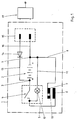
- FIG. 1 the housing 1 of the device is indicated by a dash-dotted line and otherwise the schematic circuit is shown.
- a DC battery 2 is housed in the housing, the positive pole 3 of which is connected to a switch 4.
- a line 5 leads from the switch 4 to an anode 6.
- the negative pole 7 of the direct current battery 2 is connected via line 8 to a cathode 9 which is formed in two parts, a passage opening 10 being formed between the two parts.
- a lamp 12 is arranged in a branch 11 of the circuit bridging the direct current battery 2 and the switch 4. As can be seen, the lamp 12 only burns when the switch 4 is closed.
- a line 13 leads from the positive pole 3 via a discharge protection diode 14 to a plug or socket 15.
- a corresponding line 16 leads from the negative pole 7 to the plug 15, to which a conventional charger 17, which can be connected to a socket, can be connected.
- Figure 2 shows a plan view of the device with its housing 1, which is expediently formed in several parts and has an upwardly closing housing cover 18, on the one hand an insertion funnel 19 and on the other hand a carrying handle 20 for the device.
- the design and arrangement of the insertion funnel 19 predefine an insertion direction 21 which, for example, is directed vertically from top to bottom when the device is on a table.
- FIG. 4 shows a top view or a view of the device from above with the housing cover 18 removed.
- the arrangement of the direct current battery 2 can be seen.
- the anode 6 is not shown in FIG. 4.
- FIG. 5 illustrates the mode of operation.
- the insertion funnel 19 is screwed into the housing cover 18 of the housing by means of a thread. It has a funnel-shaped shape, the smallest diameter of which is still larger than the outer diameter of the metal tube 27 of the cannula 28.
- the arrangement of the insertion funnel 19 defines the insertion direction 21 with which the cannula 28 is lowered up to its head through the insertion funnel 19 into the interior of the housing 1 of the device.
- 5 shows the two parts 23 and 24 of the cathode 9 and the passage gap 10 formed to this extent, which is smaller than the outer diameter of the metal tube 27 of the cannula 28.
- the pivotable part 24 of the cathode 9 can deflect according to arrow 25 (FIG.
- the passage opening 10 has a size which is sufficient for the metal tube 27 of the cannula 28 to pass through.
- switch 4 is closed, a cannula 28 is inserted into the device in the manner described in the insertion direction 21, the tip of the metal tube 27 reaches the anode 6, which is arranged as a solid metal block in the housing 1 and is connected to the direct current battery 2 via the line 5 connected is.
- the anode 6 is arranged obliquely to the insertion device 21 or has an oblique sliding surface 30, so that the circuit between the cathode 9 and the anode 6 is closed when the tip of the metal tube 27 strikes.
- This part of the metal tube 27 which produces the connection is flowed through by a current of approximately 100 A and, as a result of its thin walls, is strongly heated and melted.
- Melted cannula parts 31 form, which fall down into the drawer 26 arranged below and are collected there.
- a ball catch 32 secures the drawer 26 in the pushed-in position, but on the other hand allows the drawer 26 to be emptied the cannula 28 takes place continuously until the insertion process by the Placing the plastic head on the insertion funnel 19 is ended.
- the dimensioning is such that even that part of the metal tube 27 which remains with a melted end comes under sufficient heat so that the risk of infection in this regard is eliminated.
Landscapes
- Health & Medical Sciences (AREA)
- Engineering & Computer Science (AREA)
- Life Sciences & Earth Sciences (AREA)
- Animal Behavior & Ethology (AREA)
- Anesthesiology (AREA)
- Biomedical Technology (AREA)
- Heart & Thoracic Surgery (AREA)
- Hematology (AREA)
- Environmental & Geological Engineering (AREA)
- Vascular Medicine (AREA)
- General Health & Medical Sciences (AREA)
- Public Health (AREA)
- Veterinary Medicine (AREA)
- Accommodation For Nursing Or Treatment Tables (AREA)
- Infusion, Injection, And Reservoir Apparatuses (AREA)
- Surgical Instruments (AREA)
- Endoscopes (AREA)
Claims (8)
- Appareil pour rendre inutilisables des canules (28), prévues pour une utilisation unique, d'une seringue, avec un boîtier (1) comportant une ouverture d'insertion (19) de forme circulaire, qui ne permet l'insertion du tube métallique (27) de la canule (28) que dans sa direction longitudinale, et comportant un agencement à électrodes disposé en dessous de l'ouverture d'insertion (19), avec une première électrode (9), disposée immédiatement en dessous de l'ouverture d'insertion (19) et comportant une ouverture de passage (10) pour le tube métallique (27), et une seconde électrode (6), qui est configurée en forme de bloc métallique massif, et avec laquelle la pointe du tube métallique (27) vient en contact après être passée à travers la première électrode (9), pour ainsi refermer un circuit de courant en vue de mettre chaque fois en fusion la pointe du tube métallique (27), tandis que le tube métallique (27) continue d'être fondu lorsque l'on poursuit l'insertion, le déplacement d'insertion étant limité par une butée de l'ouverture d'insertion (19) prévue pour une tête de la canule (28), caractérisé en ce que le point de contact de la pointe du tube métallique (27) repose sur une surface inclinée de glissement (30) de la seconde électrode (6) pendant la totalité du déplacement d'insertion.
- Appareil selon la revendication 1, caractérisé en ce que la première électrode (9) est configurée en au moins deux pièces, en ce que deux pièces (23, 24) de la première électrode (9) forment entre elles l'ouverture de passage (10) et en ce que les deux pièces (23, 24) sont déplaçables l'une par rapport à l'autre, en opposition à la force de rappel d'un ressort (29), pour agrandir l'ouverture de passage (10).
- Appareil selon la revendication 2, caractérisé en ce que l'ouverture de passage (10) de la première électrode (9) présente en position de repos un diamètre plus petit que les tubes métalliques habituels (27) de canules (28).
- Appareil selon la revendication 2 ou 3, caractérisé en ce qu'une partie (24) de la première électrode (9) est maintenue à pivotement par rapport à l'autre partie (23).
- Appareil selon l'une des revendications 1 à 4, caractérisé en ce que l'ouverture d'insertion (19) est configurée en forme d'entonnoir d'insertion.
- Appareil selon l'une des revendications 1 à 5, caractérisé en ce que les électrodes (6, 9) peuvent être raccordées à une batterie à courant continu (2) disposée dans le boîtier (1).
- Appareil selon la revendication 6, caractérisé en ce que sur le boîtier (1) est prévu un raccordement (15) en vue du chargement de la batterie à courant continu (2) par l'intermédiaire d'un appareil de charge (17).
- Appareil selon l'une des revendications 1 à 7, caractérisé en ce que verticalement en dessous des électrodes (6, 9), un tiroir (26) est disposé dans le boîtier (1) pour réception des parties fondues (31) de canules.
Priority Applications (1)
| Application Number | Priority Date | Filing Date | Title |
|---|---|---|---|
| AT91106374T ATE103824T1 (de) | 1990-04-27 | 1991-04-19 | Geraet zum unschaedlichmachen von kanuelen. |
Applications Claiming Priority (2)
| Application Number | Priority Date | Filing Date | Title |
|---|---|---|---|
| DE9004788U | 1990-04-27 | ||
| DE9004788U DE9004788U1 (de) | 1990-04-27 | 1990-04-27 | Gerät zur Entsorgung von Einweg-Kanülen |
Publications (2)
| Publication Number | Publication Date |
|---|---|
| EP0455075A1 EP0455075A1 (fr) | 1991-11-06 |
| EP0455075B1 true EP0455075B1 (fr) | 1994-04-06 |
Family
ID=6853276
Family Applications (1)
| Application Number | Title | Priority Date | Filing Date |
|---|---|---|---|
| EP91106374A Expired - Lifetime EP0455075B1 (fr) | 1990-04-27 | 1991-04-19 | Dispositif pour rendre des canules inoffensives |
Country Status (5)
| Country | Link |
|---|---|
| US (1) | US5147304A (fr) |
| EP (1) | EP0455075B1 (fr) |
| AT (1) | ATE103824T1 (fr) |
| CA (1) | CA2041336A1 (fr) |
| DE (2) | DE9004788U1 (fr) |
Families Citing this family (19)
| Publication number | Priority date | Publication date | Assignee | Title |
|---|---|---|---|---|
| US5268549A (en) * | 1990-06-01 | 1993-12-07 | Butler William F | Method and apparatus for destroying a syringe needle |
| EP0517643A1 (fr) * | 1991-06-01 | 1992-12-09 | Adriana Beatriz Rotlander Ibanez | Appareil destructeur d'aiguilles hypodermiques |
| US5282428A (en) * | 1992-04-24 | 1994-02-01 | Advanced Disposal Systems International Limited | Medical needle incinerator and sealer |
| DE69215224D1 (de) * | 1991-06-25 | 1996-12-19 | Grevillle Peter | Verbrennungsvorrichtung,insbesondere fuer zu medizinischen zwecken gebrauchte nadeln |
| CN2094351U (zh) * | 1991-07-05 | 1992-01-29 | 谢庆隆 | 针具销毁器 |
| WO1993025250A1 (fr) * | 1992-06-11 | 1993-12-23 | Ivars Zalstrovs | Appareil d'elimination d'objets affiles |
| DE4221153C1 (en) * | 1992-06-27 | 1993-04-22 | Me Pha Tec Gmbh Medizin - Und Pharmatechnik, 5190 Stolberg, De | Disposable syringe cannulae harmless rendering unit, avoiding contamination - comprises rotatable solid roller contacting cannulae metal tube at side of rotational axis and slidable rotating in housing with opening for tube |
| FR2698273A1 (fr) * | 1992-11-24 | 1994-05-27 | Biotti Jean | Dispositif autonome de destruction d'aiguilles de seringues. |
| GB2273231B (en) * | 1992-12-04 | 1996-06-19 | Brian Edward Stanford | Incinerator device |
| JPH07195784A (ja) * | 1993-12-28 | 1995-08-01 | Canon Inc | プリンタの駆動方法 |
| GB2287407A (en) * | 1994-03-07 | 1995-09-20 | Claremont Medical Equipment Li | Electrically destroying medical implements |
| AT129U1 (de) * | 1994-05-17 | 1995-03-27 | Mth Import Export Gmbh Mth Imp | Geraet zum entsorgen von elektrisch leitenden kanaelen (injektionsnadeln) |
| GB2294622B (en) * | 1994-09-16 | 1996-11-13 | Advanced Medical Ltd | Electrical needle destroyer |
| US5637238A (en) * | 1995-01-31 | 1997-06-10 | Innovative Medical Equipment, Inc. | Apparatus for electrical destruction of medical instruments |
| FR2722971A1 (fr) * | 1995-05-12 | 1996-02-02 | Cendrier Pierre Jean Lucien | Destructeur d'aiguilles portable et autonome |
| US5741230A (en) * | 1996-07-31 | 1998-04-21 | Miller; Gary E. | Hypodermic needle extraction disposal system and device |
| US20020115987A1 (en) * | 2001-02-16 | 2002-08-22 | Path | Needle cannula removal by extraction |
| WO2002096592A1 (fr) * | 2001-05-29 | 2002-12-05 | Jackson Kenneth A | Appareil pour desintegrer electriquement des aiguilles hypodermiques |
| US9446190B2 (en) | 2012-03-09 | 2016-09-20 | Medtech Systems Inc. | Hypodermic needle assembly and related methods |
Family Cites Families (3)
| Publication number | Priority date | Publication date | Assignee | Title |
|---|---|---|---|---|
| JPS6040060A (ja) * | 1983-08-08 | 1985-03-02 | シユイ チン−ロン | ミニ形注射針廃棄器 |
| GB2211420A (en) * | 1987-10-23 | 1989-07-05 | Antonio Talluri | Improvements relating to the destruction of hypodermic needles |
| IT1216025B (it) * | 1988-03-08 | 1990-02-22 | Jeabor S A | Apparecchio atto ad operare, in modo pressoche' istantaneo, la distruzione completa dell'ago di siringhe per iniezione, subito dopo il loro impiego. |
-
1990
- 1990-04-27 DE DE9004788U patent/DE9004788U1/de not_active Expired - Lifetime
-
1991
- 1991-04-19 DE DE91106374T patent/DE59101305D1/de not_active Expired - Fee Related
- 1991-04-19 AT AT91106374T patent/ATE103824T1/de not_active IP Right Cessation
- 1991-04-19 EP EP91106374A patent/EP0455075B1/fr not_active Expired - Lifetime
- 1991-04-26 US US07/690,776 patent/US5147304A/en not_active Expired - Fee Related
- 1991-04-26 CA CA002041336A patent/CA2041336A1/fr not_active Abandoned
Also Published As
| Publication number | Publication date |
|---|---|
| CA2041336A1 (fr) | 1991-10-28 |
| DE9004788U1 (de) | 1990-08-09 |
| ATE103824T1 (de) | 1994-04-15 |
| US5147304A (en) | 1992-09-15 |
| EP0455075A1 (fr) | 1991-11-06 |
| DE59101305D1 (de) | 1994-05-11 |
Similar Documents
| Publication | Publication Date | Title |
|---|---|---|
| EP0455075A1 (fr) | Dispositif pour rendre des canules inoffensives | |
| DE2500851C3 (de) | Injektor zum Injizieren eines Kontrastmittels | |
| EP0593900B1 (fr) | Dispositif de pulvérisation fine de liquides | |
| EP0630609B1 (fr) | Dispositif à lancette pour prélèvements sanguins a des fins de diagnostique | |
| DE69121119T2 (de) | Hypodermatische Nadel/Spritzenverbindung und Einrichtung zur Entfernung der Nadeln von dieser | |
| DE69107385T2 (de) | Vorrichtung zur Schmelzentsorgung von Injektionsnadeln. | |
| DE60022222T2 (de) | Integration einer lanzette mit ihrer abziehkappe | |
| DE69117464T2 (de) | Kolbenlose Spritze | |
| CH657980A5 (de) | Einweg-knochenzementspritze. | |
| DE2747276A1 (de) | Infusionskanuelenaggregat | |
| DE1598124A1 (de) | Pipettenspitze | |
| WO1984001812A1 (fr) | Briquet, en particulier briquet a jeter | |
| DE60208284T2 (de) | Verbessertes Gerät und Methode der Entfernung einer Nadel von einer Spritze | |
| DE2123113A1 (de) | Vorrichtung zur Bestimmung einer durch Tropfen gebildeten Strömung | |
| WO2001064267A1 (fr) | Dispositif de recouvrement d'aiguille a longueur modifiable faisant partie d'un appareil d'injection | |
| WO1992022338A1 (fr) | Procede d'exploitation d'un dispositif d'administration d'une substance therapeutique medicinale liquide a un corps soumis a un traitement et dispositif de mise en ×uvre du procede | |
| DE69320145T2 (de) | Vorrichtung und verfahren zum vernichten von spritzennadeln | |
| DE4103562A1 (de) | Vorrichtung zum vollstaendigen zerstoeren von injektionsnadeln und aehnlichen gegenstaenden | |
| DE19732909C2 (de) | Mikrodosierbare Spritze | |
| DE3915397C2 (fr) | ||
| DE2427211C3 (de) | Sprühvorrichtung | |
| DE69421702T2 (de) | Methode und gerät zum zerstören von spritznadeln | |
| DE2831517A1 (de) | Automatische und tragbare einheit zum schweissen | |
| EP0510626A1 (fr) | Dispositif de maintien d'un capuchon de protection d'une aiguille d'injection | |
| DE3725745A1 (de) | Werkzeug zum ausformen von wachs |
Legal Events
| Date | Code | Title | Description |
|---|---|---|---|
| PUAI | Public reference made under article 153(3) epc to a published international application that has entered the european phase |
Free format text: ORIGINAL CODE: 0009012 |
|
| AK | Designated contracting states |
Kind code of ref document: A1 Designated state(s): AT BE CH DE DK ES FR GB GR IT LI NL SE |
|
| 17P | Request for examination filed |
Effective date: 19910919 |
|
| 17Q | First examination report despatched |
Effective date: 19920203 |
|
| RAP1 | Party data changed (applicant data changed or rights of an application transferred) |
Owner name: MEPHATEC GMBH MEDIZIN- UND PHARMATECHNIK |
|
| GRAA | (expected) grant |
Free format text: ORIGINAL CODE: 0009210 |
|
| AK | Designated contracting states |
Kind code of ref document: B1 Designated state(s): AT BE CH DE DK ES FR GB GR IT LI NL SE |
|
| PG25 | Lapsed in a contracting state [announced via postgrant information from national office to epo] |
Ref country code: GR Free format text: LAPSE BECAUSE OF FAILURE TO SUBMIT A TRANSLATION OF THE DESCRIPTION OR TO PAY THE FEE WITHIN THE PRESCRIBED TIME-LIMIT Effective date: 19940406 Ref country code: IT Free format text: LAPSE BECAUSE OF FAILURE TO SUBMIT A TRANSLATION OF THE DESCRIPTION OR TO PAY THE FEE WITHIN THE PRESCRIBED TIME-LIMIT;WARNING: LAPSES OF ITALIAN PATENTS WITH EFFECTIVE DATE BEFORE 2007 MAY HAVE OCCURRED AT ANY TIME BEFORE 2007. THE CORRECT EFFECTIVE DATE MAY BE DIFFERENT FROM THE ONE RECORDED. Effective date: 19940406 Ref country code: ES Free format text: THE PATENT HAS BEEN ANNULLED BY A DECISION OF A NATIONAL AUTHORITY Effective date: 19940406 Ref country code: SE Free format text: THE PATENT HAS BEEN ANNULLED BY A DECISION OF A NATIONAL AUTHORITY Effective date: 19940406 Ref country code: DK Effective date: 19940406 Ref country code: BE Effective date: 19940406 Ref country code: FR Effective date: 19940406 Ref country code: GB Effective date: 19940406 |
|
| REF | Corresponds to: |
Ref document number: 103824 Country of ref document: AT Date of ref document: 19940415 Kind code of ref document: T |
|
| PG25 | Lapsed in a contracting state [announced via postgrant information from national office to epo] |
Ref country code: AT Effective date: 19940419 |
|
| PG25 | Lapsed in a contracting state [announced via postgrant information from national office to epo] |
Ref country code: LI Effective date: 19940430 Ref country code: CH Effective date: 19940430 |
|
| REF | Corresponds to: |
Ref document number: 59101305 Country of ref document: DE Date of ref document: 19940511 |
|
| EN | Fr: translation not filed | ||
| GBV | Gb: ep patent (uk) treated as always having been void in accordance with gb section 77(7)/1977 [no translation filed] |
Effective date: 19940406 |
|
| REG | Reference to a national code |
Ref country code: CH Ref legal event code: PL |
|
| PLBE | No opposition filed within time limit |
Free format text: ORIGINAL CODE: 0009261 |
|
| STAA | Information on the status of an ep patent application or granted ep patent |
Free format text: STATUS: NO OPPOSITION FILED WITHIN TIME LIMIT |
|
| 26N | No opposition filed | ||
| PGFP | Annual fee paid to national office [announced via postgrant information from national office to epo] |
Ref country code: NL Payment date: 19950430 Year of fee payment: 5 |
|
| PG25 | Lapsed in a contracting state [announced via postgrant information from national office to epo] |
Ref country code: NL Effective date: 19961101 |
|
| NLV4 | Nl: lapsed or anulled due to non-payment of the annual fee |
Effective date: 19961101 |
|
| PGFP | Annual fee paid to national office [announced via postgrant information from national office to epo] |
Ref country code: DE Payment date: 20010403 Year of fee payment: 11 |
|
| PG25 | Lapsed in a contracting state [announced via postgrant information from national office to epo] |
Ref country code: DE Free format text: LAPSE BECAUSE OF NON-PAYMENT OF DUE FEES Effective date: 20021101 |