EP0455085B1 - Dispositif de tension à cliquet pour lien d'arrimage - Google Patents
Dispositif de tension à cliquet pour lien d'arrimage Download PDFInfo
- Publication number
- EP0455085B1 EP0455085B1 EP91106425A EP91106425A EP0455085B1 EP 0455085 B1 EP0455085 B1 EP 0455085B1 EP 91106425 A EP91106425 A EP 91106425A EP 91106425 A EP91106425 A EP 91106425A EP 0455085 B1 EP0455085 B1 EP 0455085B1
- Authority
- EP
- European Patent Office
- Prior art keywords
- ratchet
- tensioning
- locking
- spindle
- winding
- Prior art date
- Legal status (The legal status is an assumption and is not a legal conclusion. Google has not performed a legal analysis and makes no representation as to the accuracy of the status listed.)
- Expired - Lifetime
Links
- 230000007246 mechanism Effects 0.000 claims description 13
- 238000006073 displacement reaction Methods 0.000 claims description 5
- 238000010276 construction Methods 0.000 claims description 3
- 230000001154 acute effect Effects 0.000 claims description 2
- 239000011295 pitch Substances 0.000 claims 1
- 238000004804 winding Methods 0.000 description 18
- 238000010586 diagram Methods 0.000 description 7
- 230000000903 blocking effect Effects 0.000 description 6
- 230000008901 benefit Effects 0.000 description 3
- 230000000694 effects Effects 0.000 description 3
- 238000000034 method Methods 0.000 description 3
- 230000008569 process Effects 0.000 description 3
- 230000000284 resting effect Effects 0.000 description 3
- 208000027418 Wounds and injury Diseases 0.000 description 2
- 230000006378 damage Effects 0.000 description 2
- 208000014674 injury Diseases 0.000 description 2
- 238000003780 insertion Methods 0.000 description 2
- 230000037431 insertion Effects 0.000 description 2
- 239000004753 textile Substances 0.000 description 2
- 229910000831 Steel Inorganic materials 0.000 description 1
- 230000006835 compression Effects 0.000 description 1
- 238000007906 compression Methods 0.000 description 1
- 238000009826 distribution Methods 0.000 description 1
- 230000002349 favourable effect Effects 0.000 description 1
- 238000004519 manufacturing process Methods 0.000 description 1
- 230000009467 reduction Effects 0.000 description 1
- 239000007787 solid Substances 0.000 description 1
- 239000010959 steel Substances 0.000 description 1
- 238000003860 storage Methods 0.000 description 1
- 230000007704 transition Effects 0.000 description 1
Images




Classifications
-
- F—MECHANICAL ENGINEERING; LIGHTING; HEATING; WEAPONS; BLASTING
- F16—ENGINEERING ELEMENTS AND UNITS; GENERAL MEASURES FOR PRODUCING AND MAINTAINING EFFECTIVE FUNCTIONING OF MACHINES OR INSTALLATIONS; THERMAL INSULATION IN GENERAL
- F16G—BELTS, CABLES, OR ROPES, PREDOMINANTLY USED FOR DRIVING PURPOSES; CHAINS; FITTINGS PREDOMINANTLY USED THEREFOR
- F16G11/00—Means for fastening cables or ropes to one another or to other objects; Caps or sleeves for fixing on cables or ropes
- F16G11/12—Connections or attachments, e.g. turnbuckles, adapted for straining of cables, ropes, or wire
-
- B—PERFORMING OPERATIONS; TRANSPORTING
- B60—VEHICLES IN GENERAL
- B60P—VEHICLES ADAPTED FOR LOAD TRANSPORTATION OR TO TRANSPORT, TO CARRY, OR TO COMPRISE SPECIAL LOADS OR OBJECTS
- B60P7/00—Securing or covering of load on vehicles
- B60P7/06—Securing of load
- B60P7/08—Securing to the vehicle floor or sides
- B60P7/0823—Straps; Tighteners
- B60P7/083—Tensioning by repetetive movement of an actuating member
-
- Y—GENERAL TAGGING OF NEW TECHNOLOGICAL DEVELOPMENTS; GENERAL TAGGING OF CROSS-SECTIONAL TECHNOLOGIES SPANNING OVER SEVERAL SECTIONS OF THE IPC; TECHNICAL SUBJECTS COVERED BY FORMER USPC CROSS-REFERENCE ART COLLECTIONS [XRACs] AND DIGESTS
- Y10—TECHNICAL SUBJECTS COVERED BY FORMER USPC
- Y10T—TECHNICAL SUBJECTS COVERED BY FORMER US CLASSIFICATION
- Y10T24/00—Buckles, buttons, clasps, etc.
- Y10T24/21—Strap tighteners
-
- Y—GENERAL TAGGING OF NEW TECHNOLOGICAL DEVELOPMENTS; GENERAL TAGGING OF CROSS-SECTIONAL TECHNOLOGIES SPANNING OVER SEVERAL SECTIONS OF THE IPC; TECHNICAL SUBJECTS COVERED BY FORMER USPC CROSS-REFERENCE ART COLLECTIONS [XRACs] AND DIGESTS
- Y10—TECHNICAL SUBJECTS COVERED BY FORMER USPC
- Y10T—TECHNICAL SUBJECTS COVERED BY FORMER US CLASSIFICATION
- Y10T24/00—Buckles, buttons, clasps, etc.
- Y10T24/21—Strap tighteners
- Y10T24/2175—Cargo tie down
Definitions
- the present invention relates to a tensioning ratchet for lashing strands, which acts gradually on a lashing strand via a locking mechanism with a lashing tension necessary, for example, to secure transport goods.
- lashing strands can be designed as textile lashing straps, chains, steel cables, ropes, etc.
- a ratchet is known.
- the ratchet of this known tensioning ratchet consists of a ratchet wheel with a directed toothing and two ratchet slides running parallel to one another and mounted in a common guide slot. The two locking slides are intended to reduce the locking jumps of the locking mechanism while maintaining a relatively large tooth pitch angle, as is known from Lueger, Lexikon dertechnik, volume 1.1960, p. 530.
- the lashing tension in the known ratchet can be built up in small steps, so that the lashing string can be subjected to a high lashing tension.
- the lashing tension effective in the lashing string is abruptly reduced.
- additional loads can be applied to the lashing string by displacing the load, resulting in a so-called "whip effect" on the lashing string when released.
- This whip effect entails a comparatively high risk of injury and thus safety for the unloading team entrusted with handling the goods to be transported.
- Another disadvantage of the known ratchet is that a slipping load is no longer held steadily by the lashing string after the locking mechanism has been released.
- the invention has for its object to improve a ratchet of the type mentioned and to increase its safety and ease of use. This object is achieved by the combination of features of claim 1.
- the solution according to the invention is to provide a ratchet with two tooth locks.
- a ratchet wheel with a directed toothing which is firmly connected to the winding shaft of the device serves as a common ratchet piece for the two ratchets.
- the drive lock acting between the tensioning lever and the take-up shaft has a drive slide for the rotary drive of the take-up shaft, which is mounted so as to be longitudinally displaceable in the tensioning lever and engages in the toothing in the manner of a driver.
- the effective anti-rotation lock between the console and the take-up shaft has two locking slides mounted in the console so as to be longitudinally displaceable and offset on the circumference of the locking wheel.
- the two locking slides movably mounted in different console guide slots are distributed around the circumference of the locking wheel in such a way that both locking slides are alternately engaged with the locking wheel. So if one locking slide is engaged with the locking wheel, the other locking slide is out of engagement.
- the inventive idea is not only to gradually build up the lashing tension acting on the lashing string, but also to reduce it step by step.
- the tensioning lever which drives the take-up shaft via the drive slide, is pivotably mounted with its bearing end on the take-up shaft and has an unlocking cam projecting radially from the periphery of its bearing end.
- the drive slide can be deactivated with the toothing in a disengaged position and the tensioning lever can be pivoted away from the console in the tensioning direction such that the unlocking cam moves one of the locking slides out of the toothing into its unlocked position.
- the lashing tension acting on the lashing string is gradually reduced by the described back and forth movement of the tensioning lever, so the lashing string is released step by step. If the goods to be transported have slipped during transport or if it is determined during loosening that the goods to be transported are no longer securely resting on the transport surface, the drive pawl only has to be reactivated by moving the teeth in order to re-tension the lashing strap to secure the goods to be transported. If the cargo is again loaded with the full lashing tension, it is possible to take the necessary measures to safely unload the slipped cargo without time pressure.
- the main advantage of the device is therefore an increase in safety when releasing the lashing cord for unloading the means of transport. Another advantage is the avoidance of the whip effect mentioned by the iterative unlocking of the ratchet.
- the handling of the tensioning ratchet is additionally improved by the adjacent position of the unlocking cam and control cam described in claim 2, the unlocking cam being arranged in the tensioning direction of the control cam.
- the clamping lever which is initially resting on the console, swivels in the clamping direction into the blocking ratchet area. By pivoting further in the tensioning direction, the tensioning lever reaches the release area in which the unlocking cam moves the locking slide reciprocally out of engagement with the toothing of the locking wheel. If the lashing tension is reduced in such a way that the lashing string is only loosely around the goods to be transported, the two locking slides can be disengaged jointly by pivoting the tensioning lever in the tensioning direction by means of the control cam.
- the lashing strand winder still remaining on the winding shaft can be easily unwound from the winding shaft simply by pulling the lashing strand.
- the teaching of claim 2 enables the easy-to-use arrangement of the locking position, the release position and the open position of the clamping lever one behind the other.
- the claims 3 to 5 teach the technically favorable and structurally simple design of the clamping lever.
- the handle arranged at the end of the handle opposite the tension lever bearing end serves on the one hand as a bridging cross connection between the clamping lever side walls and on the other hand as a handle for pivoting the clamping lever.
- the filigree design of the tensioning lever advantageously reduces the own weight of the tensioning lever.
- the cross-connection yoke bridging between the tension lever side walls further stabilizes the structure of the tension lever and serves as a solid abutment for the pressurized drive slide.
- the drive slide can easily be moved out of the toothing by means of its gripping bracket.
- the handle and the gripping bar are arranged in such a way that the operator's hand is supported on the handle to move the drive slide from the toothing, and the middle finger and the ring finger extend through the gripper bar and pull the drive slide longitudinally in the direction of the handle.
- the claims 6 to 9 teach a structurally simple and technically advantageous construction of the console.
- the console has a low weight, measured by its solidity. Due to the fork-like design of both bracket-free ends, the lashing strand fixed end can be easily fixed to the console on the one hand, and the winding shaft can be easily inserted into the console on the other. However, it is also possible to mount the bracket with its attachment-free end directly on a means of transport, for example on the loading surface of a truck.
- the symmetrical construction of the tensioning ratchet according to claim 9 is also advantageous. Because of the symmetry, numerous identical parts can be used, which lowers the production unit costs for the tensioning ratchet. In addition, the symmetrical structure of the tensioning ratchet results in a symmetrical distribution of force on the tensioning ratchet when the lashing tension is applied.
- the operation of the ratchet is further improved.
- the locking slide designed in this way can easily be moved longitudinally between their extreme positions and can transmit high forces.
- the locking slides are easy to install in the console guide slots and form a robust and permanent positive connection with the console.
- the curved design of the locking slide according to claims 21 to 23 reduces the overall height of the ratchet.
- the flat ratchet fits harmoniously, especially in textile lashing strands.
- the ratchet requires less transport or storage space due to its lower height.
- the tensioning ratchet does not protrude so far from the lashing rope, so that the risk of injury is reduced and thus the safety of use of the tensioning ratchet is increased.
- the tensioning ratchet essentially consists of a base body designed as a console 1, a tensioning lever 2, two locking wheels 3, 3 'and a winding shaft 4 carrying it.
- the locking wheels 3,3' form with two locking slides 5,5 'mounted on the bracket 1. a reverse locking mechanism.
- the console 1 in turn consists of two console side walls 7, 7 'extending in the longitudinal direction 6 and a console base 9 connecting the console side walls 7, 7' in a transverse direction 8, the transverse direction 8 running at right angles to the longitudinal direction 6.
- the console base 9 and the console side walls 7, 7 ' form a U-shaped cross-sectional shape running in the transverse direction 8.
- the console side walls 7, 7 ' project fork-like at the free ends of the console 1 beyond the console base 9 in the longitudinal direction 6.
- a screw bolt 10 passes through the console side walls 7, 7 'in the transverse direction 8.
- the screw bolt 10 is used to fasten the lashing string fixed end, preferably designed as a loop, not shown in the drawings.
- the bolt-like winding shaft 4 passes through the bracket side walls 7, 7' in bearing eyes in the transverse direction 8.
- the winding shaft 4 consists of two half-bolts 11, 11 ', each of which has a substantially semicircular cross section running in the longitudinal direction 6.
- This semicircular cross-section creates on each half-bolt 11, 11 'a plan side 12, 12' extending in the transverse direction 8 and a round side 13, 13 'also extending in the transverse direction 8.
- the half-bolts 11, 11 ' are joined together to form the winding-up shaft 4 in such a way that their flat sides 12, 12' face one another and their round sides 13, 13 'are simultaneously facing away from one another.
- the plane sides 12, 12 'are not touching one another, but are spaced apart such that a space is formed between them, which serves as an insertion slot 14.
- a toothing 33 is formed in each case in the radius of the locking wheels 3, 3 '.
- the ratchet wheels 3, 3 ' have two cutouts which are semicircular in cross section, the flat lines of which face one another and the rounded lines of which face away from one another.
- the shape and dimensions of these semicircular hollow cross sections correspond approximately to the volume cross sections of the half bolts 11, 11 '.
- the half bolts 11, 11 ' penetrate the locking wheels 3, 3' in these recesses in the manner of a loose fit.
- the ratchet wheels 3, 3 ' are fixed on the take-up shaft 4 in such a way that they flank the outer side walls of the console side walls 7, 7' in parallel.
- the winding shaft 4 simultaneously passes through the fork-like bearing end of the tensioning lever 2 in such a way that the locking wheels 3, 3 'are mounted between the outer sides of the console side walls 7, 7' and the inner sides of the tensioning lever side walls 15, 15 '.
- the winding shaft 4 is secured against slipping in the transverse direction 8 by a securing bolt 43 passing through it in the longitudinal direction 6 on the outer sides of the clamping lever side walls 15, 15 'and simultaneously connects the bracket 1 with the clamping lever 2 in terms of movement.
- the handle 16 On the handle end of the tensioning lever 2 opposite the winding shaft 4, the handle 16 bridging the tensioning lever side walls 15, 15 'is fastened.
- the transverse connection yoke 17 In the longitudinal direction 6, approximately in the middle between the handle 16 and the take-up shaft 4 between the clamping lever side walls 15, 15 ', the transverse connection yoke 17 extending in the transverse direction 8 is fixed.
- the cross-connecting yoke 17 is penetrated in the direction of the handle 16 by the gripping bracket 18 of the drive slide 19.
- the drive slide 19 extends in a handle direction 20 defined by the winding shaft 4 as one end point and the handle 16 as another end point.
- a centering mandrel 21 projects from the drive slide 19 in the direction of the handle 16, in the handle direction 20.
- the centering mandrel 21 is surrounded by a helical spring element, a spiral spring 22.
- the coil spring 22 moves with its spring force the drive slide 19 towards the winding shaft 4 in the gripping direction 20, the cross-connecting yoke 17 serving as an abutment.
- the drive slide 19 passes through the tension lever side walls 15, 15 'in the transverse direction 8 in the direction of the handle 20 Slide guide slots 23, 23 'in such a way that the drive slide 19 is mounted for longitudinal displacement in the gripping direction 20 in the clamping lever side walls 15, 15'.
- the drive slide 19 forms, with the ratchet wheels 3, 3 ', the drive lock for the rotary drive of the take-up shaft 4 by means of the tensioning lever 2.
- a guide part 24 protrudes from the console base 9 like a dovetail perpendicular to the longitudinal direction 6 and the transverse direction 8. In the longitudinal direction 6, the guide part 24 is penetrated by two bearing openings 25, 25 '. In the bearing opening 25 there is a spinous extension 26 of the locking slide 5 running approximately in the longitudinal direction 6; In the bearing opening 25 'there is a spinous extension 26' of the locking slide 5 'running approximately in the longitudinal direction 6.
- the locking slides 5,5 ' are in the manner of two legs of an acute angle, the apex of which is approximately congruent with the axis of rotation of the winding shaft 4, to one another. Their distance corresponds to one and a half times the tooth pitch p shown in FIG. 2.
- the locking slides 5,5 ' pass through the console side walls 7,7' in the transverse direction 8 and are slidably mounted in the longitudinal direction 6 in console guide slots 41,41 '/ 42,42'.
- the console guide slots 41, 41 '/ 42, 42' running in the longitudinal direction 6 are formed in the console side walls 7, 7 '.
- a compression spring element is located between the guide part 24 and each of the two locking slides 5,5 '.
- this is the spiral spring element 27 which helically surrounds the spinous process 26 and in the case of the blocking slide 5 'the spiral spring element 27' which surrounds the spinous process.
- the guide part 24 serves the spiral spring elements 27, 27 'as an abutment in order to move the locking slides 5,5' with their spring force onto the locking wheels 3,3 '.
- the circumference of the shaft-free end 28, 28 'of the console side wall 7, 7' has a multiple structure.
- the cross-section of the shaft-free end circumference 28, 28 'running in the transverse direction 8, in the area of the winding shaft 4, is first curved in the area of the winding shaft 4 from the locking slides 5,5', so that the center of the circle with the center of the locking wheels 3,3 ' or the winding shaft 4 coincides.
- the diameter of this quarter-circular blocking region 29 at the shaft free end circumference 28, 28 ' has one Base circle diameter (d f ) of the toothing 33 on the ratchet wheel 3, 3 'corresponds to the pitch circle diameter.
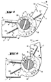
- the clamping lever 2 If the clamping lever 2 is moved with its handle 16 away from the console 1 in a clamping direction 30, it reaches a position of approximately 80 ° with respect to the console 1, the drive slide 19 striking a clamping stop 31 at the end of the semicircular blocking region 29. Due to the movement of the tensioning lever 2 in the tensioning direction 30, the take-up shaft 4 is rotated further in the tensioning direction 30 by about a quarter of a revolution. If the drive slide 19 strikes the stop 31, the tensioning lever 2 must be moved back against the tensioning direction 30 in the direction of the console 1. In this case, the drive slide 19 slides over the front flanks 32 of the teeth 33 which are rounded against the tensioning direction 30.
- one of the two locking slides 5,5 engages behind another tooth 33 on its rectilinear rear flank, which runs essentially parallel to the radial lines of the locking wheel 3,3' 34.
- the ratchet wheel 3.3 'driven by the drive slide 19 is rotated further in the clamping direction 30, the ratchet slides 5.5' in turn slide over the rounded front flanks 32 of the teeth 33, with the ratchet slide 5 and the ratchet slide 5 'alternately after half the tooth pitch p corresponding rotation in the clamping direction 30 engage behind a tooth 33 on its rear flank 34.
- the drive slide 19 is moved back and forth between the bracket 1 and the tensioning stop 31 with the tensioning lever 2 until the winding shaft 4 has traveled so many revolutions that the lashing cord fixed in its insertion slot 14 is wound around it several times and thus with the necessary lashing tension is applied.
- the drive slide 19 is moved with the tensioning lever 2 to the tensioning stop 31.
- the gripping bracket 18 With the gripping bracket 18, the drive slide 19 is pulled in the gripping direction 20 from the toothing into a position in which it can be moved via the clamping stop 31.
- the circumference of the shaft end 28, 28 ' has, in addition to the blocking area 29 in the clamping direction 30, the adjacent release area 35.
- the release area 35 in the transverse direction 8 has a rounded, circular cross section, the diameter of which is larger than the tip circle diameter (da) of the ratchet wheel 3, 3 '.
- the release area 35 is delimited by limit stops 36, 36 '.
- the clamping lever 2 is moved further in the clamping direction 30 after the drive slide 19 has been raised.
- the spiral spring 22 presses the drive slide 19, as shown in FIG. 4, into the release area 35.
- the drive slide 19 lies with its end face facing away from the gripping bracket 18 against the release area 35 and forms a sliding guide with the release area 35.
- the unlocking cam 37 formed on the circumference of the bearing end of the tensioning lever 2 and protruding in the direction of grip 20 from the tensioning lever 2 comes into contact with the locking slides 5,5 '. If the drive slide 19, as shown in FIG.
- the unlocking cam 37 bears against the end face of the locking slide 5 'in such a way that it moves in the direction of the guide part 24 and is out of engagement with the teeth 33.
- the take-up shaft 4 rotates back by a rotational distance corresponding to half a tooth pitch p against the tensioning direction 30 until the locking slide 5 engages behind a tooth 33 on its rear flank 34.
- the lashing is gradually loosened by the reciprocating movement of the tensioning lever 2 once against the tensioning direction 30 and once in the tensioning direction 30 with alternating engagement of the locking slides 5,5 'in the toothing 33.
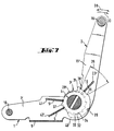
- the drive slide 19 with its gripping bracket 18 is in turn moved in the direction of the handle 16, in the direction of grip 20, and the tensioning lever 2 is further rotated in the tensioning direction 30 such that the bracket 1 and the tensioning lever 2 according to 8 have an opening angle of approximately 180 °.
- a locking groove 39 is formed in the end face of the console 1 on the circumference of the shaft-free end 28, 28 'in the clamping direction 30 in addition to the release area 35.
- the drive slide 19 engages in the latching groove 39 in this 180 ° open position.
- Tension lever side walls 15, 15 'formed control cam 40 moves in the direction of the guide member 24 such that both locking slides 5,5' are out of engagement with the teeth 33.
- 1 to 8 always show an embodiment of the ratchet with a tooth pitch angle p of 24 °, which corresponds to a number of teeth of 15.
- the ratchet is realized with a tooth pitch angle p of 33 °, which corresponds to a number of teeth of 11.
- any other tooth pitch angle p can also be realized.
- the unlocking cam 37 has a slight pitch, which means that only small forces are required to release the locking slides 5,5 ', at the same time the distance between the locking slides 5,5' increases such that the overall height of the ratchet increases .
- the unlocking cam 37 has a sharp, high pitch at a small tooth pitch angle p, which means that comparatively high forces are required to release the locking slides 5.5 ', but at the same time the distance of the locking slides 5.5' from one another is reduced such that the overall Ratchet builds very flat.
- the locking slides 50, 50 ' are curved.
- the drive slide 190 is also curved, analogous to the locking slide 50 '.
- the curved drive slide 190 is also mounted in the curved slide guide slot 230.
- the locking slides 50, 50 ' are supported with their end faces facing away from the locking wheel 3, each resting against one leg of the leg spring 270 arranged in the transverse direction 8.
- the leg spring 270 lies in a space-saving manner between the concave sides of the curved locking slide 50, 50 '.
- the locking slides 50, 50 ' lead one Pivotal movement, which consists of a movement component in the longitudinal direction 6 and a movement component in the vertical direction 44.
- the vertical direction 44 is perpendicular to both the longitudinal direction 6 and the transverse direction 8.
- the locking slides 50, 50 'curved about their axis of curvature in the drawing plane of FIG. 9 in the transverse direction 8 thus perform one of a movement component in the longitudinal direction 6 and a movement component in the vertical direction 44 resulting pivoting movement.
- the pivoting movement of the curved locking slides 50, 50 'takes place around the leg spring 270 in a partially rotating manner.
- the kinematics of the curved drive slide 190 in the curved slide guide slot 230 are analogous to the movement of the curved locking slide 50, 50 '.
- a ratchet with a large tooth pitch p and an unlocking cam 37 with a small pitch can thus be realized without this ratchet being too high.
Landscapes
- Engineering & Computer Science (AREA)
- Mechanical Engineering (AREA)
- General Engineering & Computer Science (AREA)
- Transportation (AREA)
- Transmission Devices (AREA)
- Purses, Travelling Bags, Baskets, Or Suitcases (AREA)
- Basic Packing Technique (AREA)
- Clamps And Clips (AREA)
- Ropes Or Cables (AREA)
- Package Frames And Binding Bands (AREA)
- Hand Tools For Fitting Together And Separating, Or Other Hand Tools (AREA)
- Braking Elements And Transmission Devices (AREA)
Claims (23)
- Dispositif de tension à cliquets pour lien d'arrimage, comprenant- un arbre d'enroulement (4) pour le lien d'arrimage, monté rotatif sur une console (1),- un levier de tensionnement (2) monté en rotation sur l'arbre d'enroulement (4) et formant un entraînement en rotation,- un dispositif de blocage unidirectionnel libérable à denture pour la transmission de l'entraînement en rotation entre le levier de tensionnement (2) et l'arbre d'enroulement (4), et- un dispositif de blocage unidirectionnel également libérable et à denture entre la console (1) et l'arbre d'enroulement (4) en tant que sécurité contre une rotation inverse lors du tensionnement, dans lequela) l'arbre de roulement (4) contient une roue de blocage (3, 3') mise en rotation avec lui pour le bloqueur unidirectionnel à denture,b) le levier de tensionnement (2) reçoit un loquet d'entraînement (19) qui peut être amené sous une force de rappel en engagement avec la roue de blocage (3, 3'),c) la console (1) reçoit deux loquets de blocage (5, 5') décalés en direction périphérique, qui peuvent être amenés sous une force de rappel en engagement avec la roue de blocage (3, 3'),d) le levier de tensionnement (2) porte à la périphérie de son extrémité de montage un profil de commande (40) qui sert à repousser ensemble les loquets de blocage (5, 5'), ce profil de commande sollicitant les loquets de blocage (5, 5') par pivotement du levier de tensionnement dans la direction de tensionnement (30) lorsque le loquet d'entraînement (19) est reculé, caractérisé par les éléments suivants :e) les loquets de blocage (5, 5') peuvent être déplacés dans des guidages séparés (41, 41', 42, 42') de la console, à une distance effective l'un de l'autre dans la direction de rotation,f) une came de déverrouillage (37) est agencée au voisinage du profil de commande (40) dans la direction périphérique pour reculer de manière sélective un des deux loquets de blocage (5, 5') respectifs.
- Dispositif tendeur selon la revendication 1, caractérisé en ce que la came de déverrouillage (37) est agencée au voisinage du profil de commande (40) et en avance dans la direction de tensionnement (30), à la périphérie de l'extrémité de montage du levier de tensionnement.
- Dispositif tendeur selon l'une ou l'autre des revendications 1 et 2, caractérisé en ce que les parois latérales du levier de tensionnement (15, 15') s'étendent sensiblement parallèlement et dépassent du levier de tensionnement (2) à la manière d'une fourche au niveau des extrémités libres du levier de tensionnement, une poignée (16), qui forme un pontage entre les parois latérales (15, 15') du levier de tensionnement, parallèlement à l'arbre d'enroulement (4) et en direction transversale (8), étant fixée à l'extrémité éloignée de l'extrémité de montage.
- Dispositif tendeur selon l'une ou plusieurs des revendications 1 à 3, caractérisé en ce qu'une barre de liaison transversale (17)- en forme de caisson creux,- s'étendant en direction transversale (8),- ouverte en direction de l'arbre d'enroulement (4), relie l'une à l'autre à la manière d'un pont les parois latérales (15, 15') du levier de tensionnement dans la région entre l'extrémité de montage et l'extrémité de la poignée.
- Dispositif tendeur selon la revendication 4, caractérisé en ce que le loquet d'entraînement (19) est monté en translation et sollicité par un ressort contre la barre de liaison transversale (17) dans des fentes de guidage (23, 23') dans les parois latérales (15, 15') du levier de tensionnement, et en ce que son extrémité éloignée de l'arbre d'enroulement (4) porte un arceau de saisie (18) destiné au déplacement longitudinal en direction de la barre de liaison transversale (17).
- Dispositif tendeur selon l'une ou plusieurs des revendications précédentes, caractérisé en ce que les extrémités libres de la console (1) opposées l'une à l'autre sont réalisées en forme de fourche, et en ce que la console présente entre les extrémités libres et en direction transversale (8) une section transversale approximativement en forme de U,- dont les bras du U forment les parois latérales (7, 7') de la console agencées sensiblement parallèlement dans la direction longitudinale (6), et- dont le fond du U est le fond de la console (9).
- Dispositif tendeur selon la revendication 6, caractérisé en ce qu'un boulon vissé (10) traverse les parois latérales (7, 7') de la console en direction transversale (8) et en formant un pont, à l'extrémité libre de fixation de la console (1), pour la fixation de l'extrémité fixe du lien d'arrimage, réalisée de préférence sous la forme d'une boucle, et en ce que l'arbre d'enroulement (4) est monté à l'extrémité libre d'arbre (28, 28') éloignée de l'extrémité libre de fixation, dans des lumières de montage des parois latérales (7, 7') de la console.
- Dispositif tendeur selon l'une ou plusieurs des revendications précédentes, caractérisé en ce que deux roues de blocage (3, 3') sont disposées sur l'arbre d'enroulement (4) entre les côtés extérieurs des parois latérales (7, 7') de la console et les côtés intérieurs des parois latérales (15, 15') du levier de tensionnement, et sont raccordées en coopération de formes avec l'arbre d'enroulement (4).
- Dispositif tendeur selon l'une ou plusieurs des revendications précédentes, caractérisé par une structure symétrique par rapport à son axe longitudinal médian qui s'étend dans la direction longitudinale (6), de telle manière que l'arbre d'enroulement (4) porte deux roues de blocage (3, 3'), et par le fait que deux parois latérales de console et de façon correspondante deux parois latérales (15, 15') de levier de tensionnement sont prévues.
- Dispositif tendeur selon l'une ou plusieurs des revendications précédentes, caractérisé en ce que le levier de tensionnement (2) est posé dans sa position de repos à la manière d'un couvercle sur la console (1), et qu'il peut être pivoté pour l'entraînement en rotation de l'arbre d'enroulement (4) dans la direction de tensionnement (30) dans une position à 80° de la console (1), le loquet d'entraînement (19) s'engageant en coopération de formes par sa face frontale en arrière d'une dent de blocage (33) d'une roue de blocage (5, 5').
- Dispositif tendeur selon la revendication 10, caractérisé en ce que dans la position à 80° du levier de tensionnement (2) le loquet d'entraînement (19) engagé dans la denture (33) est appliqué contre une butée de tensionnement (31) qui dépasse radialement à la périphérie de l'extrémité libre d'arbre (28, 28').
- Dispositif tendeur selon la revendication 11, caractérisé en ce que dans le but de permettre la poursuite de la rotation du levier de tensionnement (2) dans la direction de tensionnement (30) au-delà de la position à 80°, le loquet d'entraînement (19) peut être soulevé par déplacement longitudinal dans la direction de la poignée (16) hors de la denture (33), et que son appui contre la butée de tensionnement (31) peut être annulé dans cette position de dégagement.
- Dispositif tendeur selon la revendication 12, caractérisé en ce que la région de la périphérie de l'extrémité libre (28, 28') voisine de la butée de tensionnement (31) dans la direction de tensionnement (30) sur la console (1) dépasse radialement le diamètre extérieur (da) de la roue de blocage voisine (3, 3'), et est arrondie de manière convexe de telle manière qu'elle forme un guidage coulissant pour l'extrémité du loquet d'entraînement dirigée vers la roue de blocage (3, 3').
- Dispositif tendeur selon la revendication 13, caractérisé par une position inactive du loquet d'entraînement (19) lorsque l'extrémité du loquet d'entraînement est en contact contre le guidage coulissant tandis qu'elle est simultanément dégagée de la denture (33).
- Dispositif tendeur selon l'une des revendications 12 à 14, caractérisé en ce que le guidage coulissant forme une région de libération (35) constituée dans la direction de tensionnement (30) par deux butées de délimitation (36, 36') qui dépassent radialement hors de la périphérie de l'extrémité libre (28, 28').
- Dispositif tendeur selon l'une ou plusieurs des revendications précédentes, caractérisé en ce que les loquets de blocage (5, 5') s'engagent dans la denture (33) ménagée sur la roue de blocage (3, 3') à une distance l'un de l'autre égale à un pas et demi (p) de la denture.
- Dispositif tendeur selon la revendication 16, caractérisé en ce que les loquets de blocage (5, 5') sont montés de manière à pouvoir se déplacer longitudinalement sur la console, dans des fentes de guidage (41, 41'/42, 42') de la console, en étant dirigés l'un par rapport à l'autre à la manière des côtés d'un angle aigu dont le sommet est situé approximativement sur l'axe de rotation de l'arbre d'enroulement (4) qui s'étend dans la direction transversale (8).
- Dispositif tendeur selon l'une des revendications 15, 16 ou 17, caractérisé par une première position de libération du levier de tensionnement (2) et du dispositif à encliquetage agissant entre la console (1) et l'arbre d'enroulement (4), de telle manière que le loquet d'entraînement (19) est appliqué contre la butée de délimitation (36') et la came de déverrouillage (37) maintient l'un des loquets de blocage (5) dégagé par rapport à la denture (33).
- Dispositif tendeur selon l'une des revendications 15, 16 ou 17, caractérisé par une seconde position de libération du levier de tensionnement (2) et du dispositif à encliquetage agissant entre la console (1) et l'arbre d'enroulement (4), de telle manière que le loquet d'entraînement (19) est appliqué contre la butée de délimitation (36), et la came de déverrouillage (37) maintient l'autre loquet de blocage (5') dégagé par rapport à la denture (33).
- Dispositif tendeur selon les revendications 18 et 19, caractérisé par la capacité de détendre pas à pas le lien d'arrimage par déplacement en va-et-vient alternatif du levier de tensionnement (2) entre la première et la seconde position de libération.
- Dispositif tendeur selon les revendications 16 et 17, caractérisé en ce que l'un des loquets de blocage (50, 50') est incurvé autour d'un axe de courbure qui s'étend dans la direction transversale (8).
- Dispositif tendeur selon la revendication 21, caractérisé en ce que les loquets de blocage (50, 50') et le loquet d'entraînement (190) sont incurvés en forme de segment de cercle et sont guidés dans des fentes de guidage (230, 410, 420) correspondantes en forme de segments de cercle.
- Dispositif tendeur selon la revendication 22, caractérisé en ce que les côtés concaves des loquets de blocage (50, 50') sont dirigés l'un vers l'autre, et en ce qu'un ressort à bras (270) situé entre eux peut être fixé de telle manière qu'un loquet de blocage respectif (50, 50') est appliqué contre un bras du ressort en vue d'être sollicité par un effort.
Applications Claiming Priority (4)
| Application Number | Priority Date | Filing Date | Title |
|---|---|---|---|
| DE9005003 | 1990-05-03 | ||
| DE9005003U | 1990-05-03 | ||
| DE9102777U | 1991-03-08 | ||
| DE9102777U DE9102777U1 (de) | 1991-03-08 | 1991-03-08 | Spann- und Zurrvorrichtung für Zurrstränge |
Publications (2)
| Publication Number | Publication Date |
|---|---|
| EP0455085A1 EP0455085A1 (fr) | 1991-11-06 |
| EP0455085B1 true EP0455085B1 (fr) | 1994-03-16 |
Family
ID=25956607
Family Applications (1)
| Application Number | Title | Priority Date | Filing Date |
|---|---|---|---|
| EP91106425A Expired - Lifetime EP0455085B1 (fr) | 1990-05-03 | 1991-04-22 | Dispositif de tension à cliquet pour lien d'arrimage |
Country Status (10)
| Country | Link |
|---|---|
| US (1) | US5103536A (fr) |
| EP (1) | EP0455085B1 (fr) |
| CN (1) | CN1019658B (fr) |
| AT (1) | ATE103043T1 (fr) |
| AU (1) | AU630800B2 (fr) |
| BR (1) | BR9101773A (fr) |
| CA (1) | CA2040850C (fr) |
| DE (1) | DE59101180D1 (fr) |
| DK (1) | DK0455085T3 (fr) |
| ES (1) | ES2051044T3 (fr) |
Cited By (4)
| Publication number | Priority date | Publication date | Assignee | Title |
|---|---|---|---|---|
| US6769155B2 (en) | 2000-08-18 | 2004-08-03 | Mammut Tec Ag | Tensioning and relaxing element |
| WO2007003636A1 (fr) | 2005-07-05 | 2007-01-11 | Spanset Inter Ag | Cliquet de serrage permettant de serrer et de maintenir des moyens de serrage |
| DE102010002052A1 (de) | 2009-06-15 | 2010-12-16 | Innoform Ag | Spanngurt sowie Befestigungsvorrichtung für einen solchen Spanngurt |
| DE202017003206U1 (de) | 2017-06-17 | 2017-12-15 | Marc Hoffmann | Sicherungsspanner |
Families Citing this family (73)
| Publication number | Priority date | Publication date | Assignee | Title |
|---|---|---|---|---|
| DE9102777U1 (de) * | 1991-03-08 | 1992-07-02 | Spanset Inter Ag, Oetwil Am See | Spann- und Zurrvorrichtung für Zurrstränge |
| US5282706A (en) * | 1992-09-24 | 1994-02-01 | Indiana Mills & Manufacturing, Inc. | Retractable tie-down assembly |
| JPH06284912A (ja) * | 1993-03-31 | 1994-10-11 | Takigen Seizo Kk | 帯の締め張りに使用するラチェットバックル |
| DE29506142U1 (de) * | 1995-04-08 | 1996-08-01 | Spanset Inter Ag, Oetwil Am See | Spannratsche |
| FR2749791B1 (fr) * | 1996-06-14 | 1998-09-18 | Virax Sa | Dispositif d'etau, destine particulierement au maintien d'un tube ou analogue |
| DE29615284U1 (de) * | 1996-09-04 | 1996-10-31 | Westdeutscher Drahtseil-Verkauf Dolezych GmbH & Co, 44147 Dortmund | Spannvorrichtung zum Spannen von Gurten o.dgl. |
| JP2840230B2 (ja) * | 1997-03-12 | 1998-12-24 | タキゲン製造株式会社 | ラチェットバックル装置 |
| DE19731286C2 (de) * | 1997-07-21 | 1999-07-08 | Huang Han Ching | Spannvorrichtung für Gurte und dergleichen |
| GB2341888B (en) * | 1998-09-24 | 2000-11-08 | Huang Han Ching | Strap tightening/loosening device |
| US6047451A (en) * | 1999-05-20 | 2000-04-11 | Constance F. Berger | Belt shortening device |
| US6230370B1 (en) | 1999-08-10 | 2001-05-15 | Constance F. Berger | Belt shortening device with side access slot |
| US6081976A (en) * | 1999-11-03 | 2000-07-04 | Sunshine Kids Juvenile Products, Llc | Belt shortening device |
| US6241174B1 (en) | 1999-11-10 | 2001-06-05 | Constance F. Berger | Belt shortening device |
| USD428806S (en) * | 1999-12-10 | 2000-08-01 | Sunshine Kids Juvenile Products, Llc | Belt shortening device |
| US6273353B1 (en) | 2000-03-16 | 2001-08-14 | Constance F. Berger | Belt shortening device with L-shaped spindle and improved guide tabs |
| US6279847B1 (en) | 2000-03-16 | 2001-08-28 | Constance F. Berger | Belt shortening device with L-shaped spindle |
| US6524041B1 (en) | 2000-11-16 | 2003-02-25 | Danut Voiculescu | Locking ratchet for a lashing mechanism |
| US6457701B1 (en) * | 2001-04-18 | 2002-10-01 | Chi-San Huang | Strap tightener |
| DE20118135U1 (de) * | 2001-11-07 | 2002-01-17 | Hu, Yu Fang, Ta-Li, Taichung | Vorrichtung mit Sperrädern für die sichere Freigabe eines Bandes |
| US6637077B2 (en) | 2001-11-21 | 2003-10-28 | Douglas H Doty | Adjustable strap |
| GB2385396B (en) * | 2002-02-11 | 2004-08-04 | Roblon Ind Fiber | A method for connecting two structures together using a strap and tensioning device for use in such a method |
| CN2545095Y (zh) * | 2002-04-12 | 2003-04-16 | 宁波旭力金属制品有限公司 | 分步释放拉紧机机壳 |
| USD489246S1 (en) | 2002-07-15 | 2004-05-04 | O'neill Mfg., Inc. | Ratchet assembly for use in tie down |
| US20040181914A1 (en) * | 2003-03-21 | 2004-09-23 | Lu Jung Wen | Strapping device with an anti-reversing design used when preparing to loose the strap |
| US6880810B1 (en) * | 2003-10-14 | 2005-04-19 | Ratchet Co., Ltd. | Belt reel assembly for fastening goods on a truck |
| DE10349229B4 (de) * | 2003-10-23 | 2013-05-29 | Wolfcraft Gmbh | Bandspanner und zugehörige Spannbacken |
| USD507480S1 (en) | 2003-11-04 | 2005-07-19 | Master Lock Company | Ratchet bumper |
| US7510168B1 (en) * | 2006-10-02 | 2009-03-31 | Jia Hsin Press Cast Industry Co., Ltd. | Cable tension device having a tension adjustable function |
| US20080232922A1 (en) * | 2007-03-20 | 2008-09-25 | Vincent Chang | Cargo bracing device |
| DE102007039436B4 (de) | 2007-08-21 | 2009-09-10 | Doll Fahrzeugbau Ag | Spannwinde |
| US20100199474A1 (en) * | 2009-02-12 | 2010-08-12 | Cole Renfroe | Safety ratchet |
| USD642031S1 (en) | 2009-03-05 | 2011-07-26 | Cequent Consumer Products, Inc. | Ratchet for load-securing tie-down strap |
| US7877846B1 (en) | 2009-05-15 | 2011-02-01 | Weiguo Chen | Ratchet buckle with excess strap retention arm and double layered arm |
| US20110061213A1 (en) * | 2009-09-14 | 2011-03-17 | Win Chance Metal Co., Ltd. | Hand puller with a structure of double stopping plates |
| US8312601B2 (en) * | 2010-01-22 | 2012-11-20 | Han-Ching Huang | Strap-tightening device |
| US8141852B1 (en) * | 2010-02-18 | 2012-03-27 | Gresham Ronald E | Strap securing system |
| EP2386446A1 (fr) * | 2010-05-11 | 2011-11-16 | Han-Ching Huang | Appareil de tension d'une sangle |
| USD675498S1 (en) | 2010-06-18 | 2013-02-05 | Master Lock Company Llc | Ratchet |
| CN102275644A (zh) * | 2011-08-15 | 2011-12-14 | 四川欧曼机械有限公司 | 一种棘轮式捆绑带拉紧器 |
| USD681411S1 (en) | 2011-08-30 | 2013-05-07 | Master Lock Company Llc | Ratchet lock |
| JP6162122B2 (ja) * | 2011-09-16 | 2017-07-12 | アーマー ホールディングス リミテッドArmour Holdings Limited | ストラップ用ラチェット装置及びその使用 |
| USD700486S1 (en) | 2012-05-08 | 2014-03-04 | Cequent Consumer Products, Inc. | Handle for a ratchet assembly |
| CN102828652B (zh) * | 2012-09-13 | 2015-08-05 | 无锡山羊轻工机电有限公司 | 一种棘轮式紧线器 |
| WO2014145858A2 (fr) | 2013-03-15 | 2014-09-18 | Bitol Designs, Llc | Cathéter résistant à une occlusion et procédé d'utilisation |
| US9155359B1 (en) | 2013-09-16 | 2015-10-13 | Dennis Morgan Bailey | Ratchet buckle with locking mechanism |
| US9771014B2 (en) | 2014-02-07 | 2017-09-26 | Raymond Brown | Step release tension assembly |
| CN105020333B (zh) * | 2014-04-28 | 2019-02-12 | 杭州友凯船艇有限公司 | 一种搭扣 |
| DE102014115146A1 (de) | 2014-10-17 | 2016-04-21 | Wihag Fahrzeugbausysteme Gmbh | Spannratsche |
| US9634386B2 (en) | 2015-01-19 | 2017-04-25 | Christopher C. Dundorf | Apparatus for safely securing radiation-transparent panels covering the antenna service bays of wireless telecommunication towers and methods of installing the same |
| USD894700S1 (en) * | 2015-04-10 | 2020-09-01 | Winston Products Llc | Open handle ratchet |
| US11278440B2 (en) | 2015-06-09 | 2022-03-22 | Christopher Richard Showalter | Orthopedic device providing metered toe traction with variable adduction, dorsiflexion and rotation angles, including lateral glide of the first metatarsal head |
| CN105539264A (zh) * | 2015-12-31 | 2016-05-04 | 天津美格工业设计有限公司 | 一种车用紧绳器 |
| CN105599962A (zh) * | 2016-02-19 | 2016-05-25 | 高峰 | 一种双头绳索牵引器 |
| CN105966660B (zh) * | 2016-07-11 | 2018-07-10 | 台州市永派包装设备有限公司 | 手动捆扎机 |
| CN206476161U (zh) * | 2016-11-18 | 2017-09-08 | 宁波市鄞州安红工具厂 | 绑带拉紧器 |
| USD820058S1 (en) * | 2017-01-24 | 2018-06-12 | Winston Products Llc | Ratchet handle |
| USD826017S1 (en) * | 2017-01-24 | 2018-08-21 | Winston Products Llc | Ratchet handle |
| CN107140249B (zh) * | 2017-05-22 | 2019-06-28 | 彭州市长庆全成技术开发有限公司 | 拉紧器 |
| CN107315306A (zh) * | 2017-06-23 | 2017-11-03 | 丹阳市瑞华光学元件有限公司 | 一种便于手动调节的安防镜头 |
| USD861448S1 (en) * | 2017-12-08 | 2019-10-01 | Zhangjiagang Smk Mfg. Co., Ltd. | Retractable ratchet tie down |
| CN108750174B (zh) * | 2018-08-22 | 2024-06-14 | 张卫 | 便携式绑扎器 |
| US11406162B2 (en) * | 2020-11-11 | 2022-08-09 | Nite Ize, Inc. | Systems and methods for an improved ratcheting device including pivoting tooth |
| CN113043940B (zh) * | 2021-03-10 | 2022-08-30 | 万智慧 | 一种自动收紧拉紧器 |
| CN113848355A (zh) * | 2021-10-09 | 2021-12-28 | 国网辽宁省电力有限公司铁岭供电公司 | 直流电阻类专用试验工具 |
| USD1053685S1 (en) * | 2022-08-04 | 2024-12-10 | Hampton Products International Corporation | Ratchet handle |
| US12186599B2 (en) * | 2022-11-02 | 2025-01-07 | Pure Safety Group, Inc. | Ratcheting strap adjuster |
| CN115848420B (zh) * | 2023-02-21 | 2023-05-05 | 四川工程职业技术学院 | 一种旅游观光缆车防护机构及观光缆车 |
| CN116968618B (zh) * | 2023-07-28 | 2025-11-21 | 宁波旭力金属制品有限公司 | 汽车安全拉紧装置 |
| CN117068926B (zh) * | 2023-10-10 | 2023-12-15 | 江苏东方力神吊装设备有限公司 | 一种吊装带长度调节装置 |
| US20250162489A1 (en) * | 2023-11-21 | 2025-05-22 | Zhengwu Song | Ratcheting Device with a Safe Damping Mechanism and its Use Method |
| CN117602153A (zh) * | 2023-12-29 | 2024-02-27 | 宏光空降装备有限公司 | 一种确定捆带收紧力的定力棘轮收紧机构 |
| US20250276633A1 (en) * | 2024-03-01 | 2025-09-04 | Hyundai Translead | Compression spring dual-ratchet winch for tie-down systems |
| JP2025180870A (ja) * | 2024-05-31 | 2025-12-11 | 尾道造船株式会社 | ラッシングベルト固定装置 |
Family Cites Families (8)
| Publication number | Priority date | Publication date | Assignee | Title |
|---|---|---|---|---|
| SE408695B (sv) * | 1977-10-31 | 1979-07-02 | Goteborgs Bandveveri Ab | Anordning vid organ for atspenning och lasning av sling eller lastband |
| SE412557C (sv) * | 1978-04-28 | 1985-07-15 | Holmbergs Fab Ab Brdr | Bandstreckare |
| GB2105805B (en) * | 1981-07-10 | 1985-07-03 | Spanset Inter Ag | Ratchet device for tightening belts surrounding loads on trailers |
| CH658823A5 (de) * | 1981-11-06 | 1986-12-15 | Rud Ketten Rieger & Dietz | Spannvorrichtung. |
| EP0145643B1 (fr) * | 1983-12-06 | 1993-10-06 | RUD-Kettenfabrik Rieger & Dietz GmbH u. Co. | Dispositif de liaison d'éléments d'assemblage, de dispositifs tendeurs et/ou de contrôle avec des sangles |
| DE3344486C1 (de) * | 1983-12-06 | 1990-10-04 | Rud-Kettenfabrik Rieger & Dietz Gmbh U. Co, 7080 Aalen | Spannvorrichtung für Spannstränge, insbesondere Ketten oder Gurte |
| DE3344487C1 (de) * | 1983-12-06 | 1988-09-08 | Rud-Kettenfabrik Rieger & Dietz Gmbh U. Co, 7080 Aalen | Spannvorrichtung für Spannstränge, insbesondere Ketten oder Gurte |
| DE8536678U1 (de) * | 1985-12-30 | 1986-04-03 | Chuan-chou, An, Tainan | Bindegerät |
-
1991
- 1991-04-19 CA CA002040850A patent/CA2040850C/fr not_active Expired - Lifetime
- 1991-04-22 EP EP91106425A patent/EP0455085B1/fr not_active Expired - Lifetime
- 1991-04-22 ES ES91106425T patent/ES2051044T3/es not_active Expired - Fee Related
- 1991-04-22 DE DE91106425T patent/DE59101180D1/de not_active Expired - Lifetime
- 1991-04-22 AT AT91106425T patent/ATE103043T1/de not_active IP Right Cessation
- 1991-04-22 DK DK91106425.1T patent/DK0455085T3/da active
- 1991-04-22 AU AU75187/91A patent/AU630800B2/en not_active Expired
- 1991-05-02 US US07/694,839 patent/US5103536A/en not_active Expired - Lifetime
- 1991-05-02 BR BR919101773A patent/BR9101773A/pt not_active IP Right Cessation
- 1991-05-03 CN CN91102791.2A patent/CN1019658B/zh not_active Expired
Cited By (5)
| Publication number | Priority date | Publication date | Assignee | Title |
|---|---|---|---|---|
| US6769155B2 (en) | 2000-08-18 | 2004-08-03 | Mammut Tec Ag | Tensioning and relaxing element |
| WO2007003636A1 (fr) | 2005-07-05 | 2007-01-11 | Spanset Inter Ag | Cliquet de serrage permettant de serrer et de maintenir des moyens de serrage |
| DE102005031735B3 (de) * | 2005-07-05 | 2007-05-10 | Spanset Inter Ag | Spannratsche zum Spannen und Halten von Spannmitteln |
| DE102010002052A1 (de) | 2009-06-15 | 2010-12-16 | Innoform Ag | Spanngurt sowie Befestigungsvorrichtung für einen solchen Spanngurt |
| DE202017003206U1 (de) | 2017-06-17 | 2017-12-15 | Marc Hoffmann | Sicherungsspanner |
Also Published As
| Publication number | Publication date |
|---|---|
| DK0455085T3 (da) | 1994-07-25 |
| ATE103043T1 (de) | 1994-04-15 |
| CN1019658B (zh) | 1992-12-30 |
| BR9101773A (pt) | 1991-12-17 |
| EP0455085A1 (fr) | 1991-11-06 |
| US5103536A (en) | 1992-04-14 |
| CA2040850A1 (fr) | 1991-11-04 |
| DE59101180D1 (de) | 1994-04-21 |
| CA2040850C (fr) | 1995-09-19 |
| ES2051044T3 (es) | 1994-06-01 |
| AU630800B2 (en) | 1992-12-05 |
| CN1056088A (zh) | 1991-11-13 |
| AU7518791A (en) | 1991-12-05 |
Similar Documents
| Publication | Publication Date | Title |
|---|---|---|
| EP0455085A1 (fr) | Dispositif de tension à cliquet pour lien d'arrimage | |
| DE2717157C2 (de) | Gurt- bzw. Seil-Ratsche | |
| EP0429610B1 (fr) | Dispositif tendeur a cliquets pour sangle d'amarrage | |
| EP1296850B1 (fr) | Cliquet de serrage combine avec un chargeur de sangle, et chargeur de sangle correspondant | |
| EP0504557B1 (fr) | Dispositif de tension et d'amarrage pour sangles d'amarrage | |
| EP4204712B1 (fr) | Dispositif de tension pour tendre des chaînes, des sangles, des cordes ou des moyens de tension similaires | |
| DE2530919A1 (de) | Bandwinde | |
| EP0281836B1 (fr) | Dispositif de raccordement de sangle | |
| DE2716337A1 (de) | Befestigungsvorrichtung fuer container an einer wand | |
| DE3040164A1 (de) | Vorrichtung zur befestigung einer last an einer plattform | |
| CH701261B1 (de) | Spanngurt. | |
| DE102013208659A1 (de) | Transportwagen für Stückgut | |
| DE3430140A1 (de) | Gurtspannvorrichtung mit sperrung | |
| EP2617602A1 (fr) | Dispositif à rochet pour étirer des objets pouvant être enroulés | |
| DE202020103769U1 (de) | Spannvorrichtung zum Spannen von Ketten, Bändern, Seilen oder dergleichen Spannmittel | |
| DE19544932C1 (de) | Klinkenschloß für Spanngurte | |
| DE202022105125U1 (de) | Gurtspeicherfähiger Zurrgurtspanner | |
| DE10250807A1 (de) | Gurtrollenaufbau zum Befestigen von Gütern auf einem Lastkraftwagen | |
| DE102011056879A1 (de) | Gurtspannvorrichtung | |
| DE10050000A1 (de) | Spannratsche mit Gurtmagazin | |
| DE102006044403A1 (de) | Ratschenanordnung zum Spannen aufwickelbarer Gegenstände | |
| DE102016117179A1 (de) | Rückhaltevorrichtung und Rollstuhlrückhaltesystem mit einer derartigen Rückhaltevorrichtung | |
| DE29703664U1 (de) | Zweiteiliger Zurrgurt | |
| DE69508313T2 (de) | Einklappbare Kurbel für Angelwinde | |
| DE102019209794A1 (de) | Ladegutsicherungsvorrichtung und Laderaumanordnung |
Legal Events
| Date | Code | Title | Description |
|---|---|---|---|
| PUAI | Public reference made under article 153(3) epc to a published international application that has entered the european phase |
Free format text: ORIGINAL CODE: 0009012 |
|
| AK | Designated contracting states |
Kind code of ref document: A1 Designated state(s): AT BE CH DE DK ES FR GB GR IT LI LU NL SE |
|
| 17P | Request for examination filed |
Effective date: 19920206 |
|
| 17Q | First examination report despatched |
Effective date: 19930706 |
|
| GRAA | (expected) grant |
Free format text: ORIGINAL CODE: 0009210 |
|
| AK | Designated contracting states |
Kind code of ref document: B1 Designated state(s): AT BE CH DE DK ES FR GB GR IT LI LU NL SE |
|
| PG25 | Lapsed in a contracting state [announced via postgrant information from national office to epo] |
Ref country code: GR Free format text: LAPSE BECAUSE OF FAILURE TO SUBMIT A TRANSLATION OF THE DESCRIPTION OR TO PAY THE FEE WITHIN THE PRESCRIBED TIME-LIMIT Effective date: 19940316 |
|
| REF | Corresponds to: |
Ref document number: 103043 Country of ref document: AT Date of ref document: 19940415 Kind code of ref document: T |
|
| REF | Corresponds to: |
Ref document number: 59101180 Country of ref document: DE Date of ref document: 19940421 |
|
| PG25 | Lapsed in a contracting state [announced via postgrant information from national office to epo] |
Ref country code: LU Free format text: LAPSE BECAUSE OF NON-PAYMENT OF DUE FEES Effective date: 19940430 |
|
| REG | Reference to a national code |
Ref country code: ES Ref legal event code: FG2A Ref document number: 2051044 Country of ref document: ES Kind code of ref document: T3 |
|
| GBT | Gb: translation of ep patent filed (gb section 77(6)(a)/1977) |
Effective date: 19940512 |
|
| ITF | It: translation for a ep patent filed | ||
| ET | Fr: translation filed | ||
| REG | Reference to a national code |
Ref country code: DK Ref legal event code: T3 |
|
| PLBE | No opposition filed within time limit |
Free format text: ORIGINAL CODE: 0009261 |
|
| STAA | Information on the status of an ep patent application or granted ep patent |
Free format text: STATUS: NO OPPOSITION FILED WITHIN TIME LIMIT |
|
| EAL | Se: european patent in force in sweden |
Ref document number: 91106425.1 |
|
| 26N | No opposition filed | ||
| REG | Reference to a national code |
Ref country code: GB Ref legal event code: IF02 |
|
| REG | Reference to a national code |
Ref country code: CH Ref legal event code: PFA Owner name: SPANSET INTER AG Free format text: SPANSET INTER AG#EICHBUEELSTRASSE 31#8618 OETWIL AM SEE (CH) -TRANSFER TO- SPANSET INTER AG#EICHBUEELSTRASSE 31#8618 OETWIL AM SEE (CH) |
|
| PGFP | Annual fee paid to national office [announced via postgrant information from national office to epo] |
Ref country code: DK Payment date: 20090423 Year of fee payment: 19 |
|
| PGFP | Annual fee paid to national office [announced via postgrant information from national office to epo] |
Ref country code: GB Payment date: 20100324 Year of fee payment: 20 |
|
| PGFP | Annual fee paid to national office [announced via postgrant information from national office to epo] |
Ref country code: FR Payment date: 20100506 Year of fee payment: 20 Ref country code: ES Payment date: 20100423 Year of fee payment: 20 |
|
| PGFP | Annual fee paid to national office [announced via postgrant information from national office to epo] |
Ref country code: NL Payment date: 20100421 Year of fee payment: 20 Ref country code: IT Payment date: 20100429 Year of fee payment: 20 Ref country code: DE Payment date: 20100622 Year of fee payment: 20 Ref country code: AT Payment date: 20100422 Year of fee payment: 20 |
|
| PGFP | Annual fee paid to national office [announced via postgrant information from national office to epo] |
Ref country code: CH Payment date: 20100426 Year of fee payment: 20 Ref country code: BE Payment date: 20100423 Year of fee payment: 20 |
|
| PGFP | Annual fee paid to national office [announced via postgrant information from national office to epo] |
Ref country code: SE Payment date: 20100423 Year of fee payment: 20 |
|
| REG | Reference to a national code |
Ref country code: DK Ref legal event code: EBP |
|
| REG | Reference to a national code |
Ref country code: DE Ref legal event code: R071 Ref document number: 59101180 Country of ref document: DE |
|
| PG25 | Lapsed in a contracting state [announced via postgrant information from national office to epo] |
Ref country code: DK Free format text: LAPSE BECAUSE OF NON-PAYMENT OF DUE FEES Effective date: 20100503 |
|
| REG | Reference to a national code |
Ref country code: CH Ref legal event code: PL |
|
| BE20 | Be: patent expired |
Owner name: *SPANSET INTER A.G. Effective date: 20110422 |
|
| REG | Reference to a national code |
Ref country code: NL Ref legal event code: V4 Effective date: 20110422 |
|
| REG | Reference to a national code |
Ref country code: GB Ref legal event code: PE20 Expiry date: 20110421 |
|
| PG25 | Lapsed in a contracting state [announced via postgrant information from national office to epo] |
Ref country code: GB Free format text: LAPSE BECAUSE OF EXPIRATION OF PROTECTION Effective date: 20110421 Ref country code: NL Free format text: LAPSE BECAUSE OF EXPIRATION OF PROTECTION Effective date: 20110422 |
|
| REG | Reference to a national code |
Ref country code: ES Ref legal event code: FD2A Effective date: 20120110 |
|
| PG25 | Lapsed in a contracting state [announced via postgrant information from national office to epo] |
Ref country code: ES Free format text: LAPSE BECAUSE OF EXPIRATION OF PROTECTION Effective date: 20110423 |
|
| PG25 | Lapsed in a contracting state [announced via postgrant information from national office to epo] |
Ref country code: DE Free format text: LAPSE BECAUSE OF EXPIRATION OF PROTECTION Effective date: 20110422 |