EP0455096A1 - Dispositif de remplissage de récipients, en particulier des bouteilles, avec un produit liquide - Google Patents
Dispositif de remplissage de récipients, en particulier des bouteilles, avec un produit liquide Download PDFInfo
- Publication number
- EP0455096A1 EP0455096A1 EP91106482A EP91106482A EP0455096A1 EP 0455096 A1 EP0455096 A1 EP 0455096A1 EP 91106482 A EP91106482 A EP 91106482A EP 91106482 A EP91106482 A EP 91106482A EP 0455096 A1 EP0455096 A1 EP 0455096A1
- Authority
- EP
- European Patent Office
- Prior art keywords
- bell
- locking
- container
- container carrier
- filling
- Prior art date
- Legal status (The legal status is an assumption and is not a legal conclusion. Google has not performed a legal analysis and makes no representation as to the accuracy of the status listed.)
- Granted
Links
Images




Classifications
-
- B—PERFORMING OPERATIONS; TRANSPORTING
- B67—OPENING, CLOSING OR CLEANING BOTTLES, JARS OR SIMILAR CONTAINERS; LIQUID HANDLING
- B67C—CLEANING, FILLING WITH LIQUIDS OR SEMILIQUIDS, OR EMPTYING, OF BOTTLES, JARS, CANS, CASKS, BARRELS, OR SIMILAR CONTAINERS, NOT OTHERWISE PROVIDED FOR; FUNNELS
- B67C3/00—Bottling liquids or semiliquids; Filling jars or cans with liquids or semiliquids using bottling or like apparatus; Filling casks or barrels with liquids or semiliquids
- B67C3/02—Bottling liquids or semiliquids; Filling jars or cans with liquids or semiliquids using bottling or like apparatus
- B67C3/06—Bottling liquids or semiliquids; Filling jars or cans with liquids or semiliquids using bottling or like apparatus using counterpressure, i.e. filling while the container is under pressure
- B67C3/10—Bottling liquids or semiliquids; Filling jars or cans with liquids or semiliquids using bottling or like apparatus using counterpressure, i.e. filling while the container is under pressure preliminary filling with inert gases, e.g. carbon dioxide
-
- B—PERFORMING OPERATIONS; TRANSPORTING
- B65—CONVEYING; PACKING; STORING; HANDLING THIN OR FILAMENTARY MATERIAL
- B65B—MACHINES, APPARATUS OR DEVICES FOR, OR METHODS OF, PACKAGING ARTICLES OR MATERIALS; UNPACKING
- B65B55/00—Preserving, protecting or purifying packages or package contents in association with packaging
- B65B55/02—Sterilising, e.g. of complete packages
- B65B55/04—Sterilising wrappers or receptacles prior to, or during, packaging
- B65B55/10—Sterilising wrappers or receptacles prior to, or during, packaging by liquids or gases
-
- B—PERFORMING OPERATIONS; TRANSPORTING
- B67—OPENING, CLOSING OR CLEANING BOTTLES, JARS OR SIMILAR CONTAINERS; LIQUID HANDLING
- B67C—CLEANING, FILLING WITH LIQUIDS OR SEMILIQUIDS, OR EMPTYING, OF BOTTLES, JARS, CANS, CASKS, BARRELS, OR SIMILAR CONTAINERS, NOT OTHERWISE PROVIDED FOR; FUNNELS
- B67C3/00—Bottling liquids or semiliquids; Filling jars or cans with liquids or semiliquids using bottling or like apparatus; Filling casks or barrels with liquids or semiliquids
- B67C3/02—Bottling liquids or semiliquids; Filling jars or cans with liquids or semiliquids using bottling or like apparatus
- B67C3/22—Details
- B67C3/26—Filling-heads; Means for engaging filling-heads with bottle necks
- B67C3/2642—Filling-heads; Means for engaging filling-heads with bottle necks specially adapted for sterilising prior to filling
-
- B—PERFORMING OPERATIONS; TRANSPORTING
- B67—OPENING, CLOSING OR CLEANING BOTTLES, JARS OR SIMILAR CONTAINERS; LIQUID HANDLING
- B67C—CLEANING, FILLING WITH LIQUIDS OR SEMILIQUIDS, OR EMPTYING, OF BOTTLES, JARS, CANS, CASKS, BARRELS, OR SIMILAR CONTAINERS, NOT OTHERWISE PROVIDED FOR; FUNNELS
- B67C3/00—Bottling liquids or semiliquids; Filling jars or cans with liquids or semiliquids using bottling or like apparatus; Filling casks or barrels with liquids or semiliquids
- B67C3/02—Bottling liquids or semiliquids; Filling jars or cans with liquids or semiliquids using bottling or like apparatus
- B67C3/22—Details
- B67C3/26—Filling-heads; Means for engaging filling-heads with bottle necks
- B67C2003/2688—Means for filling containers in defined atmospheric conditions
- B67C2003/2691—Means for filling containers in defined atmospheric conditions by enclosing one container in a chamber
Definitions
- the invention relates to a device for filling containers, in particular for filling bottles, according to the preamble of claim 1 and claim 31.
- a device or a bottle filling machine for the aseptic filling of liquid contents, a device or a bottle filling machine is known (DE-OS 38 09 855), the filling elements of which each have a bell which is open at its lower end.
- the pressure in the respectively closed bell is absorbed by the machine upper part carrying the filling elements and by the lifting device, which among other things. a significant additional load on the machine upper part and the lifting device and thus above all also means additional wear on the lifting device.
- the invention has for its object to develop a device of the type mentioned in such a way that it avoids additional wear and tear on the machine head and / or existing lifting devices and other means for generating the relative movement between bell and container carrier with little wear and optimal operation.
- a device is designed according to the characterizing part of claim 1 and claim 31.
- the closed bell and the closing element closing this bell in the locking position of the locking elements also form a self-contained system with regard to the forces generated by a pressure in the chamber. It is therefore not necessary, for example, to pass on forces caused by the pressure in the chamber to external parts carrying the bell, the filling element or the closing element.
- the entire machine can therefore be easily dimensioned, particularly with regard to construction, bearings, etc.
- the closing element is, for example, a cover which can be inserted manually into the respective bell and / or the container carrier forming a base for the containers, the opening of the bell then being able to be closed or opened by relative movement between the bell and the container carrier in the filling element axis.
- a lid which can be manually inserted into the bell and removed from it is preferably used to close the bell for cleaning purposes.
- the container carrier serves to close the bell in the most varied of procedures when filling the container, for example in the case of steam sterilization, prestressing with a pressurized gas, etc. If the device is designed with a container carrier closing the bell for cleaning purposes, this is also preferred manually insertable and removable covers provided. With appropriate design of the means for the relative movement between the bell and the container carrier, the latter can also be used to close the bell when cleaning.
- the control and / or actuation of the at least one locking element provided on and / or interacting with the container carrier is preferably carried out mechanically or by fluid actuation, for example by compressed air, with the control and / or actuation being carried out by the in a basic, possible embodiment Lift of the respective lifting element takes place. At least the mobile ones Locking elements are then provided on that part (bell or container carrier) which is moved up and down by the lifting device.
- control and / or actuation of the at least one locking element provided on or interacting with the container carrier takes place using control cams which interact with stationary control elements, past which the container carrier is moved past.
- a seal is provided which is used to reduce wear, i.e. in order to achieve a long service life when the chamber or bell is closed, it bears against a sealing surface on the container carrier or on the bell, which is arranged essentially in a plane perpendicular to the filling element axis.
- the seal preferably has at least one sealing lip which bears against the sealing surface, preferably with a contact pressure generated by the pressure inside the bell.
- the device according to the invention which is preferably designed as a filling machine with a plurality of filling elements, each with a bell and a container carrier, is suitable not only for the aseptic filling mentioned at the outset, but in particular also for other procedures in which a closed and preferably with a pressure actable chamber is necessary during the process or at least expedient.
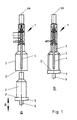
- each filling element 1 is a filling element, which is provided in the usual way with a large number of similar filling elements on the circumference of a part (rotor) of a bottle filling machine which rotates around a vertical machine axis and which is used to fill the bottles 2 with a liquid filling material (e.g. still or carbonated drinks) ) serves.
- Each filling element 1 has the usual design and is provided with a bell 3 open on its underside, which is arranged with its central axis in the vertical direction and coaxially with a filling element axis VA and, in the embodiment shown, encloses a filling tube 4 of the filling element 1 over its entire length .
- a filling element axis VA e.g. still or carbonated drinks
- the bell 3 can completely accommodate the bottle 2 to be filled in each case.
- the bottle 2 stands in the usual way with its base 2 'on a bottle holder provided below the filling element 1, which is formed by a bottle plate 5 which can be moved up and down in the vertical direction by a lifting device 6 (not shown) in accordance with the double arrow A. , in such a way that at the bottle inlet and at the bottle outlet of the bottle filling machine, the bottles 2 can be applied to and removed from a bottle plate 5, respectively, without being impeded by the filling element 1 or the bell 3.
- the respective bottle plate 5 with the associated bottle 2 is raised to such an extent that it closes the bell 3 at its lower opening or at the edge area 3 'there, so that the respective bottle 2 is closed Space is accommodated, which for the most varied of procedures when filling, for example for steam sterilization, for prestressing with a pressurized gas, etc. may be necessary.
- a head 7 is provided on the upper end of a lifting cylinder forming the lifting device 6, which surrounds the upper end of the lifting device 6 with a sleeve-like section 7 'and is fastened to it.
- a plate element 8 which forms the base for the bottles 2 and which is arranged with its central axis in the vertical direction in the direction of this central axis or of the filling element axis VA is displaceably guided, specifically with the aid of a pin-like projection 9 which projects beyond the underside of the element 8 and which engages in the interior of the sleeve-like section 7 ′′.
- the extension which is arranged coaxially with the axis VA and has an outer diameter which is reduced in comparison to the projection 9, extends through an opening formed in the region of the collar 11 and is provided at its lower end with a stop 14 with overload protection.
- the actual locking element of the bottle plate 5a consists of a locking ring 15 which is made in one piece from a flat material made of spring steel and which, on an inner ring or conical section 15 ', has a plurality of finger or wing-like sections 15''and / or 15''which project outwards. ' having.
- the sections 15 '' differ from the sections 15 '''essentially only in that the sections 15''are rather finger-like with a constant width and the sections 15''' are more segment-like with a width that increases towards the outside.
- the locking ring 15 can have the sections 15 '' and 15 '''either separately or in combination.
- the locking ring 15 is shaped in such a way that it also widens like a funnel in the region of the sections 15 ′′ and 15 ′′ ′′. With an inner edge of the section 15 'which does not have the sections 15''and / or 15''', the locking ring 15 bears against and surrounds an annular shoulder 7 '''of the head 7 formed at the upper end of the section 7'' a section 7 '''' which has a reduced outside diameter compared to section 7 ''.
- the axis of the locking ring 15 is axially aligned with the axis VA, in such a way that the sections 15 ′′ and / or 15 ′′ ′′ rest with their free ends against the underside 8 ′′ of the element 8 and one in the region of these free ends have a greater distance from the axis VA than at the transition region to the section 15 '.
- the bell 3 is formed on its underside so that when the bottle plate 5a or its plate element 8 is closed, it can move into the opening of the bell 3, so that the plate element 8 is enclosed on its circumference by the lower, thickened edge region 3a 'and Finds a stop on the bell 3, which then prevents the plate element 8 from moving upward or moving further into the bell 3.
- the abovementioned stop is formed by a collar 16,
- the bell 3 and the bottle plate 5a are hereby positively locked to one another in the manner shown on the left in FIG. 2.
- An absolutely tight seal of the closed bell is also achieved by a sealing ring 18, which is provided in an annular groove 19 on the inner surface of the edge region 3a 'and bears against the circumferential surface thereof when the plate element 8 is inserted into the bell 3.
- the sealing ring 18 is essentially V-shaped in cross-section and is arranged such that the open side of this V-shaped cross-section faces the pressure-loaded side of the region to be sealed. This ensures a particularly effective and reliable seal.
- FIGS. 4 and 5 show two modifications, which differs from the embodiment of FIG. 2 essentially only in that instead of the sealing ring 18 a sealing ring 19 or 20 is used, which in turn has a V-shaped cross section, with its However, the open side is directed radially inwards, and that in addition the plate element 8 is provided on its upper side 8 'in the region of the edge with a lower-lying ring-like sealing surface 21, against which the sealing ring 19 or 20 abuts with a lip-like section when the bell 3 is closed .
- the advantage of the modification according to FIGS. 4 and 5 compared to the embodiment according to FIG. 2 is that when the bell 3 is opened and closed there is practically no friction between the plate element 8 and the respective seal 19 or 20, i.e.
- the sealing surfaces 19 and 20 are therefore subject to much less wear than the sealing ring 18.
- the sealing surface 21 is lower than the top 8 'or standing surface for the bottles 2, but also lower than the sliding plates or sliding surfaces provided at the bottle inlet and outlet, so that the sealing surface is also protected against wear and tear.
- the sealing surface 21 is preferably covered by the sliding plates there.
- the plate element 8 in the region of its lower side 8' ' has a radially projecting flange or Has collar 8 '' 'which, when the bell 3 is closed, bears against the underside of the edge region 3a'. This allows 3 smooth, easy-to-clean surfaces inside the bell.
- the collar 8 can be cleaned without difficulty.
- FIG. 6 shows an embodiment which differs from the embodiment according to FIG. 2 essentially in that the bottle plate 5b can be locked on the bell 3 by pneumatic means.
- the bottle plate 5b has the basic function of the plate element 8
- locking segments 26 are provided at predetermined intervals around the axis VA, which can be displaced radially to the axis VA such that the locking segments 26 are arranged in a first position with a radially outer locking section 26 'within the circumference of the plate element 22 and protrude in a second, locking position with their locking portion 26 'each over the circumferential surface of the plate element 22.
- three locking segments 26 are provided.
- the locking segments 26 are so biased by spring means, for example by a common worm spring 27, that they are normally in the non-locking position.
- a pneumatic actuation device which in the embodiment shown is formed by a tubular membrane 28, the locking segments 26 can be moved against the action of the worm spring 27 by acting on the interior of the membrane 28 with a pressure to the outside into the locking position.
- the interior of the membrane 28 is connected via channels 29, 30 and 31 to a chamber formed by the recess 24.
- the plate element 22 of the bottle plate 5b When the bell 3 is closed, the plate element 22 of the bottle plate 5b is first moved into the bell 3, the locking segments 26 being in their unlocked position and the chamber formed by the recess 24 via an opening 32 provided in the head 25 communicates with the atmosphere.
- the head 25 moves under tensioning of a compression spring 33 when the plate element is stationary 22 further upwards, which is closed by the section 23 'in the opening 32 and a valve 35 is opened to a compressed air line via a plunger 34 protruding from the section 23', so that via this valve 35 and the channels 29-31 compressed air into the Interior of the membrane 28 can flow in, whereby the locking segments 26 are moved radially outward into their locking position, in which they engage with their locking portions 26 'in an annular groove 36 on the inner surface of the edge region 3b'.
- Unlocking takes place automatically in that when the head 25 is moved downward, the valve 35 is closed and at the same time the opening 32 is released from the section 23 ', so that with the venting of the interior of the membrane 28, the locking segments 26 move into their non-locking position move back.
- FIG. 7 shows such an embodiment.
- the bottle plate 5c there consists of a plate element element 37 corresponding to the plate element 8, which on a head 38 provided on the lifting device 6 in the direction of the axis VA by a predetermined amount or stroke against a spring action. namely against the action of the compression spring 12 is displaceable.
- the shape of the head 38 largely corresponds to that of the head 7.
- the bottle plate 5c is practically identical to the bottle plate 5a.
- the bottle plate 5c has several, for example at least three, locking bolts 39 as locking elements, which are arranged radially to the axis VA in the plate element 37 in the region of the underside of this element, in such a way that these locking bolts 39 are in a non-locking position with their radially outer end or locking portion 39 'within the circumferential line of the plate element 37 and a return spring 40 can be moved radially outwards from this position against the action, so that the ends 37' into one Engage recess or groove 41, which is provided on the inner surface of the edge region 3c 'of the bell 3.
- locking bolts 39 as locking elements, which are arranged radially to the axis VA in the plate element 37 in the region of the underside of this element, in such a way that these locking bolts 39 are in a non-locking position with their radially outer end or locking portion 39 'within the circumferential line of the plate element 37 and a return spring 40 can be moved radially outwards from
- the locking bolts 39 are actuated by a wedge or conical surface 42 which is provided on the outer surface of the sleeve-like section 38 '' corresponding to the section 7 '', in the region of the upper end of this section in such a way that in the bell completely introduced and thereby held plate element 37 and with the head 38 moving further upward, the radially inner ends 39 ′′ of the locking bolts 39 come to rest against the conical surface 42 and the locking bolts 39 are thereby increasingly moved outwards.
- FIG. 8 reproduced bottle plate 5d is the case.
- This bottle plate 5d consists essentially of the plate element 43 and the head 44 corresponding to the head 38.
- the head 44 is provided with a conical surface 45 such that the head 44 tapers in the region of this conical surface from the upper end .
- the split ring 46 made of spring wire which surrounds the axis VA essentially concentrically, sits on the conical surface 45.
- the plate element 43 forms an annular surface 47, likewise concentrically enclosing the axis VA and essentially lying in a plane perpendicular to this axis.
- the plate element 43 is guided on the head 44 in the same way as the plate element 8 on the head 7, inserted into the open end of the glock 3 in such a way that the plate element 43 enclosed by the edge region 3d 'does not move any further upwards If the head 44 moves further upwards, the ring 46 is increasingly spread apart radially to the axis VA by the conical surface 45 and then finally lies in one before the upper end of the head 44 comes into contact with the plate element 43 the inner surface of the edge region 3d 'provided groove 48, in such a way that the annular contact surface 47, which is provided immediately after the peripheral surface of the plate element 43, can be supported on the upper region of the ring 46 and the ring 46 with its lower Supported area at an edge of the groove 48 there.
- the ring 46 thus spread then prevents the bell
- the ring 46 does not protrude beyond the circumferential surface of the plate element 43 in the non-spread state, as shown in the right half in FIG. 8, so that the plate element 43 is inserted to close the bell 3 (with the ring 46 not yet spread) or when the bell 3 is reopened (with the ring 46 no longer spread) can be moved out of the bell.
- FIGS. 9 and 10 show a further possible embodiment of a bottle plate 5e, in which the bell 3 is locked on the bottle plate or on the plate element 49 by means of a locking disk 50 which is freely rotatable on the underside of the plate element 49 about the axis VA is provided.
- the locking disc 50 has a central opening 51, with which this disc is freely rotatably supported on a circular cylindrical projection 52 projecting from the underside of the plate element 49, between two rings 53 and 54, of which the lower ring 54 against axial displacement is secured and the upper ring 53 is acted upon by a plurality of compression springs 55, so that the locking disc 50 is clamped at the edge of the opening 51 by the force of the compression springs 55 between the rings 53 and 54 and accordingly only when overcome a torque predetermined by this clamping can be rotated about the axis VA.
- the locking disk 50 On its outer circumference, the locking disk 50 is provided with a plurality of locking segments 56, which also protrude radially over the peripheral surface of the plate element 59, while the locking disk 50 does not otherwise protrude over this peripheral surface.
- the plate element 49 is fastened to a head 58 provided on the lifting device 6 by means of an extension 57, which projects beyond the lower end of the projection 52.
- the head 58 is designed as a threaded sleeve which is screwed onto the upper end of the lifting device 6 and is closed by a bottom region at its end which projects beyond the lifting device.
- the extension 57 extends through an opening 59 of this floor area and is secured or held in the head 58 by a stop 60 corresponding to the stop 14 with overload protection.
- the edge area 3e 'of the bell 3 is designed such that the plate element 49 can be inserted into the bell together with the locking disk 50 to close the bell 3 and then both elements are enclosed by the edge area 3e'.
- projections 61 assigned to the locking segments 56 are provided, in an arrangement corresponding to the distribution of the locking segments 56 around the axis VA such that in the angular positions of the locking disk 50, which correspond to the non-locking position, all the projections 61 are located in the areas between the locking segments 56.
- FIG. 9 shows the non-locking position in the left half and the locking position of the locking disk 50 in the right half.
- the control of the locking disc 50 i.e. the switching of this disc by half the division for locking and unlocking takes place via external fixed, i.e. Control elements not co-moving with the rotor of the filling machine, which interact with pin-shaped control cams 62 and 63.
- the latter lie with their axis parallel to the axis VA and are provided on the locking disc 50 so that they protrude from the underside of this locking disc.
- Each control cam 62 is located on the outer circumference of the locking disc 50 in the area between two successive locking segments 56.
- the control cams 63 which are shorter in comparison to the control cams 62, are each provided in the area of a locking segment 56, namely in a somewhat larger radial one in comparison to the control cams 62 Distance from the central axis VA.
- control cams 62 and 63 Due to the different length and the different radial spacing of the control cams 62 and 63, it is possible to provide separate, fixed control elements for the control cams 62 and separate control elements for the control cams 63, so that the correct position for each locking disk 50 depending on the To ensure the respective angular position of the rotor of the bottle filling machine.
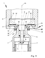
- FIG. 11 shows, as a further embodiment, a bottle plate 5f which represents a preferred modification of the bottle plate 5a and differs from it only in that several levers 64 are provided instead of the locking ring 15 or the sections 15 '' or 15 ''' are. Otherwise, the bottle plate 5f corresponds in terms of its design and construction to the bottle plate 5a, so that in FIG. 11 the same reference numerals as in FIG. 2 are used for elements which correspond in principle to the bottle plate 5a in terms of shape and function.
- the levers 64 for example three or four at equal angular intervals the axles VA are provided distributed, are pivotally mounted at one end by means of a hinge pin 65 at the upper end of the section 7 ′′ of the head 7 about the axis of the respective hinge pin 65.
- the axes of all the pivot pins 65 lie in a common plane running perpendicular to the filling element axis VA and form the tangents to a common imaginary circle surrounding this axis VA.
- the levers are provided by a common compression spring 66 which surrounds the section 7 'in the region of its upper end, which is supported with its upper end against the lever 65 and with its lower end against a collar 67 projecting beyond the outer surface of the section 7'' 64 is biased into its non-locking position, indicated by the broken line 64 'in FIG.
- a separate compression spring can also be provided for each lever 64, and a pin 69 is then provided on the collar 67 to secure it.
- Fig. 12 shows a further embodiment of a bottle plate 5g, which represents a modification of the bottle plate 5f and which, among other things.
- a plate 71 is fastened to the top 8 'of the plate element 8 by means of a screw 70, which forms the standing surface 72 for the bottles 2 to be filled as an interchangeable closing part.
- the circular disk-shaped plate 71 is provided with an annular recess which is open both to this circumference and to the top of the plate 71 and forms a sealing surface 73 which is lower than the standing surface 72 and thus the sealing surface 21 of FIGS. 4 to 6 corresponds.
- the plate 71 is preferably provided on the base 72 with a centering for the bottles 2.
- This centering is formed, for example, by centering projections, not shown, by semicircular wall sections, etc.
- the centering ensures an exact positioning with respect to the axis VA, particularly in the case of narrow-necked bottles 2, and prevents the respective filling tube 4 from coming into contact with the mouth of a narrow-necked bottle 2 when it is lifted.
- the associated bell 3 has an edge area 3g 'which essentially corresponds to the edge area 3f'.
- the locking of the bottle plate 5g in the bell 3 is carried out in the same manner as that described for the bottle plate 5f.
- an annular seal 75 is arranged at the edge region 3g 'in a groove 74 provided there, concentrically enclosing the axis VA and radially inwardly open, which has a radially inwardly projecting annular sealing lip in the region of its lower edge in FIG. 12 76, which rests against the annular sealing surface 73 from above on the bottle plate 5g closing the bell 3.
- the sealing lip 76 pressed against the sealing surface 73, whereby the transition between bell 3 and bottle plate 5g is reliably sealed.
- the seal 75 is also subject to extremely little wear.
- a channel 77 is provided in the edge area 3g, which opens into the interior of the bell 3 directly above the ring seal 75 and thus, when the bell 3 is closed, at a short distance above the standing surface 72.
- the channel 77 is provided on the outside of the bell 3 with a channel or connected to a line 78 which leads to a valve arrangement 79 provided on the bell 3 and shown only in principle in FIG. 12.
- the deep arrangement of channel 77 i.e. the arrangement of this channel directly above the ring seal 75 has the advantage, for example, in the case of steam treatment or steam exiting this channel, that a bottle 2 is flowed around from top to bottom by the steam.
- FIGS. 13 and 14 show a closing cover 80 with which the bells 3 can be closed at their lower end, specifically when the bottle filling machine is to be cleaned with liquid cleaning media in a closed circuit.
- the cover 80 consists essentially of a plate element 81 which fits into the lower, open end of the respective bell and closes this open end of the bell 3 after insertion, ie the plate element 81 is designed similarly to the plate element 8.
- the plate element 81 On its underside, the plate element 81 has two locking elements 82, which are radially displaceable with respect to the central axis of the plate element 81 and are biased radially outwards by a compression spring 83.
- the locking elements 82 are stamped parts made from flat material.
- each locking element 82 is provided with an elongated hole 84 and held in the region of this elongated hole with a screw 85 on the underside of the plate element 81.
- the locking elements 82 are simultaneously pivotable about the screws 85.
- On hers the radially inner end of the locking elements 82 are each provided with an eyelet 86 forming a gripping surface for a finger. By gripping these eyelets 86, the locking elements 82 can be moved inwards to unlock the respective cover 80.
- the locking elements 82 project with their radially outer ends over the circumferential surface of the cover element 81, so that when the cover 80 is inserted into a bell 3, the locking elements 82 engage in a recess formed in the interior of the bell 3, for example in the groove 17 or 41 of the Bells 3 with the edge areas 3a ', 3b', 3c ', 3f' and 3g '.
- an emptying valve 87 is provided on the cover 80.
- This essentially consists of a valve tappet 88 which is guided through the plate element 81 so as to be displaceable in the axial direction.
- the valve tappet 88 is provided with a valve plate 89 which is pressed against the upper side of the plate element 81 by a valve spring 90 and thereby closes two valve openings 91 provided in the plate element 81.
- valve tappet 88 projects beyond the underside of the cover 80 or the bell 3 closed with this cover, so that when a bottle plate, for example the bottle plate 5a, 5b, 5c, 5f or 5g, is raised against the closed bell 3, the emptying valve 87 opens via the valve tappet 88 and thus cleaning liquid present inside the bell 3 can flow off via the valve openings 81.
- At least one cycle of the bottle filling machine ensures that the bells 3 are completely emptied before the covers 80 are removed, which in particular also avoids the risk of accidents caused by sharp, caustic cleaning liquids.
- the bells 3 are closed by the bottle plates 5a-5g and the associated locking means for a wide variety of procedures when filling the bottles 2, while the lid 80 is used in the cleaning to close the bells 3.
- the bottle plates 5a - 5g it is also possible to use the bottle plates 5a - 5g to close the bells 3 for cleaning.
- the lifting devices for the bottle plates 5a - 5g are designed so that all bottle plates 5a - 5g each remain in the raised position during cleaning, even when the bottle filling machine is rotating.
- the lifting devices have the lifting devices or lifting cylinders which are normally used and which are prestressed by a compressed gas in the sense of lifting the bottle plates 5a-5g, each of which is provided with a cam roller 92 and which cooperate with a control cam 93 to lower the bottle plates 5a-5g, a segment 94 is provided at the start of the start-up side of the control curve 93.
- This segment can be moved from an effective position, in which it is located in the movement space of the cam rollers 92 and thus forms the start of the start side of the cam 93, to an inactive position in which the segment 94 is arranged outside the path of movement of the cam rollers 92 is.
- the cam rollers 92 move past the control cam 93 on their upper line of motion when the bottle filling machine rotates, i.e. the bottle plates 5a - 5g are not lowered and the bells 3 remain closed for the cleaning process.
Landscapes
- Engineering & Computer Science (AREA)
- Mechanical Engineering (AREA)
- Chemical & Material Sciences (AREA)
- Chemical Kinetics & Catalysis (AREA)
- Filling Of Jars Or Cans And Processes For Cleaning And Sealing Jars (AREA)
Applications Claiming Priority (4)
| Application Number | Priority Date | Filing Date | Title |
|---|---|---|---|
| DE4013736 | 1990-04-28 | ||
| DE4013736 | 1990-04-28 | ||
| DE4109731 | 1991-03-25 | ||
| DE4109731A DE4109731A1 (de) | 1990-04-28 | 1991-03-25 | Vorrichtung zum fuellen von behaeltern, insbesondere flaschen mit einem fluessigen fuellgut |
Publications (2)
| Publication Number | Publication Date |
|---|---|
| EP0455096A1 true EP0455096A1 (fr) | 1991-11-06 |
| EP0455096B1 EP0455096B1 (fr) | 1994-07-06 |
Family
ID=25892680
Family Applications (1)
| Application Number | Title | Priority Date | Filing Date |
|---|---|---|---|
| EP91106482A Expired - Lifetime EP0455096B1 (fr) | 1990-04-28 | 1991-04-23 | Dispositif de remplissage de récipients, en particulier des bouteilles, avec un produit liquide |
Country Status (6)
| Country | Link |
|---|---|
| US (1) | US5167266A (fr) |
| EP (1) | EP0455096B1 (fr) |
| JP (1) | JPH04242592A (fr) |
| BR (1) | BR9101688A (fr) |
| DE (2) | DE4109731A1 (fr) |
| ES (1) | ES2057650T3 (fr) |
Cited By (1)
| Publication number | Priority date | Publication date | Assignee | Title |
|---|---|---|---|---|
| WO2019002461A3 (fr) * | 2017-06-28 | 2019-05-02 | Krones Ag | Dispositif de traitement d'un récipient dans un système de remplissage par un produit de remplissage |
Families Citing this family (7)
| Publication number | Priority date | Publication date | Assignee | Title |
|---|---|---|---|---|
| DE4232323A1 (de) * | 1992-09-26 | 1994-03-31 | Seitz Enzinger Noll Masch | Vorrichtung zur Überwachung der Wärmebehandlung bzw. Sterilisation von Flaschen o. dgl. Behälter bei einer Behälter-Behandlungsmaschine |
| DE4307521C2 (de) * | 1993-03-10 | 1999-01-07 | Khs Masch & Anlagenbau Ag | Füllelement für Füllmaschinen zum Abfüllen eines flüssigen Füllgutes in Flaschen o. dgl. Behälter |
| DE19612322C2 (de) * | 1996-03-28 | 2002-09-26 | Tetra Laval Holdings & Finance | Vorrichtung und Verfahren zum Sterilisieren von Behältern und zum Füllen derselben mit fließfähigen Nahrungsmitteln |
| DE602005025793D1 (de) * | 2004-11-16 | 2011-02-17 | Elopak Systems | Vorrichtung und verfahren zur behälterbefüllung |
| CN111017277A (zh) * | 2020-01-02 | 2020-04-17 | 无锡华工大光电智能科技有限公司 | 一种胶囊咖啡填充封装机 |
| CN111620289A (zh) * | 2020-06-30 | 2020-09-04 | 广东绿禾生物科技有限公司 | 黑加仑饮料灌装消毒一体机 |
| US12239608B2 (en) * | 2022-01-28 | 2025-03-04 | Express Scripts Strategic Development, Inc. | Methods and apparatus for performing liquid medication bottle-splitting operations |
Citations (3)
| Publication number | Priority date | Publication date | Assignee | Title |
|---|---|---|---|---|
| EP0303135A1 (fr) * | 1987-08-01 | 1989-02-15 | Seitz Enzinger Noll Maschinenbau Aktiengesellschaft | Procédé pour le remplissage aseptique resp. stérile de récipients avec des liquides ainsi que l'installation pour la mise en oeuvre dudit procédé |
| EP0334288A1 (fr) * | 1988-03-24 | 1989-09-27 | Seitz Enzinger Noll Maschinenbau Aktiengesellschaft | Procédé pour remplir des récipients avec un produit liquide dans des conditions aseptiques voire stériles ainsi que dispositif pour la mise en oeuvre |
| GB2218079A (en) * | 1988-04-27 | 1989-11-08 | Mclennon J L Ltd | Packaging |
Family Cites Families (7)
| Publication number | Priority date | Publication date | Assignee | Title |
|---|---|---|---|---|
| DE583843C (de) * | 1931-06-20 | 1933-11-27 | Mathias Josef Kautz | Vorrichtung zur Herstellung kohlensaeurehaltiger Getraenke |
| US2289135A (en) * | 1939-11-22 | 1942-07-07 | D R Minogue | Carbonating apparatus |
| FR880538A (fr) * | 1941-06-07 | 1943-03-29 | Maybach Motorenbau Gmbh | Embrayage à griffes |
| US2536299A (en) * | 1945-04-23 | 1951-01-02 | Jessie F Smith | Pressure filling system |
| GB1128323A (en) * | 1964-10-30 | 1968-09-25 | Nat Res Dev | Sterilising and filling bottles |
| FR2540754A1 (fr) * | 1983-02-15 | 1984-08-17 | Serac Sa | Dispositif permettant le nettoyage d'une tete de remplissage sans demontage de celle-ci |
| SU1423451A1 (ru) * | 1986-10-20 | 1988-09-15 | Псковский Специализированный Конструкторско-Технологический Институт Механизации Мелиоративного Строительства И Ремонта Машин | Устройство дл вакуумной расфасовки сыпучих материалов |
-
1991
- 1991-03-25 DE DE4109731A patent/DE4109731A1/de not_active Withdrawn
- 1991-04-23 ES ES91106482T patent/ES2057650T3/es not_active Expired - Lifetime
- 1991-04-23 DE DE59102097T patent/DE59102097D1/de not_active Expired - Lifetime
- 1991-04-23 EP EP91106482A patent/EP0455096B1/fr not_active Expired - Lifetime
- 1991-04-26 US US07/692,360 patent/US5167266A/en not_active Expired - Fee Related
- 1991-04-26 BR BR919101688A patent/BR9101688A/pt not_active IP Right Cessation
- 1991-04-26 JP JP3097503A patent/JPH04242592A/ja not_active Withdrawn
Patent Citations (3)
| Publication number | Priority date | Publication date | Assignee | Title |
|---|---|---|---|---|
| EP0303135A1 (fr) * | 1987-08-01 | 1989-02-15 | Seitz Enzinger Noll Maschinenbau Aktiengesellschaft | Procédé pour le remplissage aseptique resp. stérile de récipients avec des liquides ainsi que l'installation pour la mise en oeuvre dudit procédé |
| EP0334288A1 (fr) * | 1988-03-24 | 1989-09-27 | Seitz Enzinger Noll Maschinenbau Aktiengesellschaft | Procédé pour remplir des récipients avec un produit liquide dans des conditions aseptiques voire stériles ainsi que dispositif pour la mise en oeuvre |
| GB2218079A (en) * | 1988-04-27 | 1989-11-08 | Mclennon J L Ltd | Packaging |
Cited By (2)
| Publication number | Priority date | Publication date | Assignee | Title |
|---|---|---|---|---|
| WO2019002461A3 (fr) * | 2017-06-28 | 2019-05-02 | Krones Ag | Dispositif de traitement d'un récipient dans un système de remplissage par un produit de remplissage |
| CN110799448A (zh) * | 2017-06-28 | 2020-02-14 | 克朗斯公司 | 用于在填充产品灌装设备中处理容器的装置 |
Also Published As
| Publication number | Publication date |
|---|---|
| EP0455096B1 (fr) | 1994-07-06 |
| DE59102097D1 (de) | 1994-08-11 |
| DE4109731A1 (de) | 1991-10-31 |
| ES2057650T3 (es) | 1994-10-16 |
| JPH04242592A (ja) | 1992-08-31 |
| US5167266A (en) | 1992-12-01 |
| BR9101688A (pt) | 1991-11-26 |
Similar Documents
| Publication | Publication Date | Title |
|---|---|---|
| DE69505898T2 (de) | Verschliessvorrichtung zum Zusammensetzen von, mit pumpbetätigten Sprühkapseln versehenen, Flaschen | |
| EP2244967B1 (fr) | Elément de remplissage pour le remplissage de conteneurs par une matière de remplissage liquide ainsi que machine de remplissage | |
| EP2915773B1 (fr) | Dispositif et procédé de remplissage d'un récipient avec un produit de remplissage | |
| WO2007118607A1 (fr) | Élément de remplissage et machine de remplissage avec élément de remplissage | |
| EP3693333B1 (fr) | Dispositif de traitement d'un récipient | |
| EP0455096B1 (fr) | Dispositif de remplissage de récipients, en particulier des bouteilles, avec un produit liquide | |
| DE8915914U1 (de) | Verschließmaschine umlaufender Bauart | |
| WO2008141761A1 (fr) | Machine de traitement | |
| EP2285727A1 (fr) | Élément de remplissage et machine de remplissage équipée d'éléments de remplissage de ce type | |
| DE2612089C3 (de) | Abfüllvorrichtung | |
| EP1630125B1 (fr) | Dispositif de bouchage de bouteille ou similaire | |
| DE2123865B2 (de) | Füllelement | |
| DE4005000A1 (de) | Gegendruck-fuellmaschine zum fuellen von dosen oder dergleichen behaelter | |
| DE4208549C2 (de) | Behandlungsstation für eine Vorrichtung zum Behandeln von KEG, insbesondere zum Reinigen oder Füllen von KEG | |
| EP2844604A1 (fr) | Dispositif de levage pour des machines de manipulation de récipients ainsi que machine de manipulation de récipients | |
| CH681955A5 (fr) | ||
| DE3908582A1 (de) | Vorrichtung zum verschliessen von flaschen | |
| DE1642102A1 (de) | Maschine zum Sterilisieren und Fuellen von Behaeltern | |
| DE4129452A1 (de) | Verschliessmaschine | |
| DE9417044U1 (de) | Hubvorrichtung für Behälterträger einer Füllmaschine umlaufender Bauart | |
| DE3019489C2 (de) | Gegendruckgetränkefülleinrichtung | |
| DE3616829A1 (de) | Fuellmaschine zum fuellen von gefaessen, insbesondere flaschen mit einem fluessigen fuellgut | |
| EP0416473B1 (fr) | Tête de remplissage pour embouteilleuse à contre-pression | |
| DE3931834A1 (de) | Fuellorgan fuer fuellmaschinen zum fuellen von dosen oder dergleichen behaelter | |
| DE8802596U1 (de) | Gefäßfüllmaschine |
Legal Events
| Date | Code | Title | Description |
|---|---|---|---|
| PUAI | Public reference made under article 153(3) epc to a published international application that has entered the european phase |
Free format text: ORIGINAL CODE: 0009012 |
|
| AK | Designated contracting states |
Kind code of ref document: A1 Designated state(s): DE ES FR GB IT NL |
|
| 17P | Request for examination filed |
Effective date: 19911121 |
|
| 17Q | First examination report despatched |
Effective date: 19930105 |
|
| RAP1 | Party data changed (applicant data changed or rights of an application transferred) |
Owner name: KHS MASCHINEN- UND ANLAGENBAU AKTIENGESELLSCHAFT |
|
| GRAA | (expected) grant |
Free format text: ORIGINAL CODE: 0009210 |
|
| AK | Designated contracting states |
Kind code of ref document: B1 Designated state(s): DE ES FR GB IT NL |
|
| REF | Corresponds to: |
Ref document number: 59102097 Country of ref document: DE Date of ref document: 19940811 |
|
| GBT | Gb: translation of ep patent filed (gb section 77(6)(a)/1977) |
Effective date: 19940725 |
|
| ET | Fr: translation filed | ||
| ITF | It: translation for a ep patent filed | ||
| REG | Reference to a national code |
Ref country code: ES Ref legal event code: FG2A Ref document number: 2057650 Country of ref document: ES Kind code of ref document: T3 |
|
| PLBE | No opposition filed within time limit |
Free format text: ORIGINAL CODE: 0009261 |
|
| STAA | Information on the status of an ep patent application or granted ep patent |
Free format text: STATUS: NO OPPOSITION FILED WITHIN TIME LIMIT |
|
| 26N | No opposition filed | ||
| PGFP | Annual fee paid to national office [announced via postgrant information from national office to epo] |
Ref country code: ES Payment date: 19960409 Year of fee payment: 6 |
|
| PGFP | Annual fee paid to national office [announced via postgrant information from national office to epo] |
Ref country code: GB Payment date: 19960419 Year of fee payment: 6 |
|
| PGFP | Annual fee paid to national office [announced via postgrant information from national office to epo] |
Ref country code: NL Payment date: 19960430 Year of fee payment: 6 |
|
| PG25 | Lapsed in a contracting state [announced via postgrant information from national office to epo] |
Ref country code: GB Effective date: 19970423 |
|
| PG25 | Lapsed in a contracting state [announced via postgrant information from national office to epo] |
Ref country code: ES Free format text: LAPSE BECAUSE OF NON-PAYMENT OF DUE FEES Effective date: 19970424 |
|
| PG25 | Lapsed in a contracting state [announced via postgrant information from national office to epo] |
Ref country code: NL Effective date: 19971101 |
|
| GBPC | Gb: european patent ceased through non-payment of renewal fee |
Effective date: 19970423 |
|
| NLV4 | Nl: lapsed or anulled due to non-payment of the annual fee |
Effective date: 19971101 |
|
| REG | Reference to a national code |
Ref country code: ES Ref legal event code: FD2A Effective date: 19990201 |
|
| PGFP | Annual fee paid to national office [announced via postgrant information from national office to epo] |
Ref country code: FR Payment date: 20100506 Year of fee payment: 20 |
|
| PGFP | Annual fee paid to national office [announced via postgrant information from national office to epo] |
Ref country code: DE Payment date: 20100423 Year of fee payment: 20 Ref country code: IT Payment date: 20100426 Year of fee payment: 20 |
|
| REG | Reference to a national code |
Ref country code: DE Ref legal event code: R071 Ref document number: 59102097 Country of ref document: DE |
|
| PG25 | Lapsed in a contracting state [announced via postgrant information from national office to epo] |
Ref country code: DE Free format text: LAPSE BECAUSE OF EXPIRATION OF PROTECTION Effective date: 20110423 |