EP0455106A1 - Procédé et installation pour revêtir en série des pièces d'oeuvre d'un matériau de revêtement conducteur - Google Patents
Procédé et installation pour revêtir en série des pièces d'oeuvre d'un matériau de revêtement conducteur Download PDFInfo
- Publication number
- EP0455106A1 EP0455106A1 EP91106533A EP91106533A EP0455106A1 EP 0455106 A1 EP0455106 A1 EP 0455106A1 EP 91106533 A EP91106533 A EP 91106533A EP 91106533 A EP91106533 A EP 91106533A EP 0455106 A1 EP0455106 A1 EP 0455106A1
- Authority
- EP
- European Patent Office
- Prior art keywords
- container
- containers
- intermediate container
- coating material
- supply system
- Prior art date
- Legal status (The legal status is an assumption and is not a legal conclusion. Google has not performed a legal analysis and makes no representation as to the accuracy of the status listed.)
- Granted
Links
- 239000011248 coating agent Substances 0.000 title claims abstract description 35
- 238000000576 coating method Methods 0.000 title claims abstract description 35
- 239000000463 material Substances 0.000 title claims abstract description 30
- 238000000034 method Methods 0.000 title claims description 18
- 239000007921 spray Substances 0.000 claims abstract description 13
- 239000011810 insulating material Substances 0.000 claims abstract description 7
- 239000012799 electrically-conductive coating Substances 0.000 claims abstract 3
- 239000007788 liquid Substances 0.000 claims description 11
- 238000005507 spraying Methods 0.000 claims description 7
- 238000001556 precipitation Methods 0.000 claims description 6
- 238000011049 filling Methods 0.000 claims description 5
- 238000009503 electrostatic coating Methods 0.000 claims description 4
- 230000005484 gravity Effects 0.000 claims description 2
- 230000007246 mechanism Effects 0.000 claims description 2
- 239000012528 membrane Substances 0.000 claims description 2
- 230000008569 process Effects 0.000 claims description 2
- 230000001105 regulatory effect Effects 0.000 claims description 2
- 238000009434 installation Methods 0.000 claims 7
- 230000001143 conditioned effect Effects 0.000 claims 1
- 230000001276 controlling effect Effects 0.000 claims 1
- 238000012544 monitoring process Methods 0.000 claims 1
- 239000003086 colorant Substances 0.000 description 4
- 238000009413 insulation Methods 0.000 description 3
- IJGRMHOSHXDMSA-UHFFFAOYSA-N Atomic nitrogen Chemical compound N#N IJGRMHOSHXDMSA-UHFFFAOYSA-N 0.000 description 2
- 230000008901 benefit Effects 0.000 description 2
- 239000004020 conductor Substances 0.000 description 2
- 238000010276 construction Methods 0.000 description 2
- 239000012530 fluid Substances 0.000 description 2
- 238000011010 flushing procedure Methods 0.000 description 2
- 239000003973 paint Substances 0.000 description 2
- 238000004378 air conditioning Methods 0.000 description 1
- 230000008859 change Effects 0.000 description 1
- 239000003795 chemical substances by application Substances 0.000 description 1
- 230000008878 coupling Effects 0.000 description 1
- 238000010168 coupling process Methods 0.000 description 1
- 238000005859 coupling reaction Methods 0.000 description 1
- 230000001419 dependent effect Effects 0.000 description 1
- 238000001035 drying Methods 0.000 description 1
- 238000010292 electrical insulation Methods 0.000 description 1
- 238000007590 electrostatic spraying Methods 0.000 description 1
- 238000001704 evaporation Methods 0.000 description 1
- 230000008020 evaporation Effects 0.000 description 1
- 239000002360 explosive Substances 0.000 description 1
- 239000007789 gas Substances 0.000 description 1
- 239000003999 initiator Substances 0.000 description 1
- 230000004048 modification Effects 0.000 description 1
- 238000012986 modification Methods 0.000 description 1
- 229910052757 nitrogen Inorganic materials 0.000 description 1
- 238000010422 painting Methods 0.000 description 1
- 239000002245 particle Substances 0.000 description 1
- 230000000737 periodic effect Effects 0.000 description 1
- 239000002904 solvent Substances 0.000 description 1
- XLYOFNOQVPJJNP-UHFFFAOYSA-N water Substances O XLYOFNOQVPJJNP-UHFFFAOYSA-N 0.000 description 1
Images


Classifications
-
- B—PERFORMING OPERATIONS; TRANSPORTING
- B05—SPRAYING OR ATOMISING IN GENERAL; APPLYING FLUENT MATERIALS TO SURFACES, IN GENERAL
- B05B—SPRAYING APPARATUS; ATOMISING APPARATUS; NOZZLES
- B05B5/00—Electrostatic spraying apparatus; Spraying apparatus with means for charging the spray electrically; Apparatus for spraying liquids or other fluent materials by other electric means
- B05B5/16—Arrangements for supplying liquids or other fluent material
- B05B5/1608—Arrangements for supplying liquids or other fluent material the liquid or other fluent material being electrically conductive
- B05B5/1616—Arrangements for supplying liquids or other fluent material the liquid or other fluent material being electrically conductive and the arrangement comprising means for insulating a grounded material source from high voltage applied to the material
- B05B5/1625—Arrangements for supplying liquids or other fluent material the liquid or other fluent material being electrically conductive and the arrangement comprising means for insulating a grounded material source from high voltage applied to the material the insulating means comprising an intermediate container alternately connected to the grounded material source for filling, and then disconnected and electrically insulated therefrom
- B05B5/1641—Arrangements for supplying liquids or other fluent material the liquid or other fluent material being electrically conductive and the arrangement comprising means for insulating a grounded material source from high voltage applied to the material the insulating means comprising an intermediate container alternately connected to the grounded material source for filling, and then disconnected and electrically insulated therefrom an additional container being provided downstream the intermediate container
Definitions
- the invention relates to a method and a system according to the preamble of claims 1 and 11, respectively.
- the spray head of rotary atomizers or the like is connected to high voltage in order to thereby generate the field which charges the sprayed coating particles between the spray head and the grounded object to be coated.
- a coating material with high electrical conductivity such as the environmentally friendly water-soluble paints
- the insulation resistance via the line connecting the spray head to the paint supply system is too low if the supply system is at ground potential.
- the supply system which usually consists of ring lines for the individual colors, is to be grounded, since otherwise not only would considerable expenditure of insulation be required, but also the danger of explosive discharges would exist due to the large electrical capacity.
- a separate storage container for each color, which is arranged insulated from earth and from the other containers and via a color changer and a connecting line which is at high voltage potential horizontal spray device feeds.
- the connecting line is flushed with a given color and before changing to another color with solvent (water) and dried with compressed air in order to maintain the required insulation for the container which is subsequently connected to the spraying device.
- solvent water
- this system is structurally complex and bulky. There are also color losses when emptying and flushing the insulating lines and the need to dispose of the flushing agent.
- the same problem occurs with a method known from DE-OS 37 17 929, in which the color changer of an earthed supply system leads to an intermediate container and from there leads to the spraying device for electrical insulation and is dried.
- the intermediate containers are open at their top, that is, they are depressurized. This makes it one of the things required to convey the coating material to the spraying device by means of suitable pumps, which can be, for example, a larger number of atomizers distributed along a spray booth.
- the invention has for its object to provide a method and a system that make it possible to remove the coating material from two intermediate containers without their own pumps or other mechanical conveying means.
- the invention can also improve and simplify the filling and emptying of both intermediate containers. Furthermore, the invention is suitable for a compact arrangement of the intermediate containers with little construction effort, even with a large number of intermediate containers of the type described here, for other, selectable coating materials of different colors. It is important, moreover, that the high voltage does not have to be switched off during the coating operation, since the spray device is always isolated from the supply system during operation, either between the two intermediate containers or between the contents of the first tundish and the outlet of the supply system.
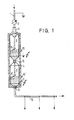
- FIG. 1 two intermediate containers A and B can be seen, which between a e.g. consisting of conventional ring lines, permanently grounded supply system, of which only one outlet line 1 is shown with a color pressure regulator 2, and a spray device (not shown) is connected, which is constantly at high voltage.
- a e.g. consisting of conventional ring lines, permanently grounded supply system of which only one outlet line 1 is shown with a color pressure regulator 2, and a spray device (not shown) is connected, which is constantly at high voltage.
- the intermediate containers A and B each consist of elongated, piston-like vessels made of pressure-resistant insulating material, which are completely closed except for closable inlets and outlets for the coating material and air.
- the two intermediate containers A and B are arranged vertically one above the other in a shell 4 of insulating material that completely encloses the container.
- the first intermediate container A has an inlet which is formed from a block-like valve 6 connected to the earthed line 1.
- the valve block bundles the conductive coating material supplied by the supply system with a pressure of, for example, 6.105 Pa (6 bar) to a jet which is directed downwards along the container axis against a liquid guiding device 8.
- the guide device 8 ensures that the coating material gets into the container with little splashing and as free of bubbles as possible, and can be formed, for example, from surfaces inclined to the container axis. It can be close to the maximum fluid level.
- the liquid level in the intermediate container A is monitored by sensors 10 of a known type, which are connected to a control device (not shown), for example for the valve 6, and stop the material supply when a maximum permissible level has been reached.
- sensors 10 of a known type, which are connected to a control device (not shown), for example for the valve 6, and stop the material supply when a maximum permissible level has been reached.
- a control device for example for the valve 6, and stop the material supply when a maximum permissible level has been reached.
- light guides, initiators, pressure sensors, etc. can be arranged on the container wall.
- the maximum level must not be exceeded in order to guarantee a distance between the conductive liquid in the container and the upper end of the container that is always sufficiently larger than the flashover distance of the high voltage applied.
- the distance can be approximately 35 cm.
- the bottom of the intermediate container can lower in a funnel-like manner or also obliquely on one side to a deepest point at which the intermediate container A has a valve 12 serving as an outlet valve of this container.
- the valve 12 also serves as an inlet valve of the lower intermediate container B, which is similar to the container A and has at its lower, also for example funnel-like or sloping end, an outlet 14 to which a conventional cabin ring line or other line 15 is connected.
- the line 15 leads via a color changer to the spraying device (not shown).
- the valve 12 also directs the liquid focused beam on a guide device 8 '.
- the maximum liquid level is monitored by a sensor 10 '. Another sensor 11 responds when the liquid level falls below a certain level.
- pressure lines are connected to both tanks A, B, by means of which a regulated pressure is generated in the tanks at a level sufficient for emptying above the ambient or atmospheric pressure.
- This excess pressure can be somewhat lower than the pressure in the outlet line 1 of the Supply system and preferably be generated with dried compressed air. Due to the pressure in the intermediate container A, it can be emptied into the lower container B after the valve 12 has been opened, it being possible to continuously or temporarily set a somewhat higher pressure in the container A than in the lower container B. Due to the excess pressure in the container B, the coating material can conveying pumps downstream of the container outlet are conveyed in the direction of the spraying device.
- the operation of the system described corresponds in principle largely to the method known from the aforementioned DE-PS 29 00 660.
- the upper intermediate container A is filled by the supply system when the valve 12 is closed, it also being at ground potential.
- the content of the lower container B which is always at the high-voltage potential of the coating device to which it is connected by the conductive material in the line 15, is the upper one Container A is isolated by the air gap of container B.
- the valve 6 is closed, the contents of the container A are placed at the high-voltage potential of the coating device and then the valve 12 is opened, so that the lower container B is now filled.
- the container A is grounded again.
- FIG. 2 differs from that according to FIG. 1 essentially only in that the two intermediate containers A, B stand side by side with vertical longitudinal axes, which has the advantage of a relatively small overall arrangement.
- Compact units are desirable in view of the fact that an arrangement with two intermediate containers A and B of the type described here is generally required for each of the often numerous selectable coating materials of different colors.
- the coating material passes from the outlet 20 of the first intermediate container A via a riser 21 to an inlet valve 22 at the upper end of the intermediate container B.
- the intermediate containers A and B are in a common or in an outer shell of insulating material, which is preferably also includes the inlet valves of the containers.
- FIG. 3 largely corresponds to that according to FIG. 2.
- a device is mounted at the upper end of each of the intermediate containers A and B, with which an inlet pipe 24 or 24 ′, which is displaceable longitudinally or parallel to the vertical container axis, into the Container can be driven.
- the tube 24, 24 ' is connected via a fluid coupling to the outlet line 1 of the supply system or to the riser 21 and is used to fill the Container moved from the illustrated retracted position down to a position in which its mouth is near the bottom of the container.
- This embodiment enables a laminar, bubble-free introduction of the liquid.
- the tube is then pulled out of the interior of the container.
- a telescopic tube construction could also be provided, in which the displaceable tube is mounted in a tube which is fixedly mounted in the container inlet.
- an axially linearly up and down movable (and / or rotatable about the container axis) device 26, 26 'can dip into the intermediate containers A and B, with which the coating material is kept in motion in the container, which among other things. prevents settling and drying during breaks.
- the lifting mechanism of the inlet tube 24, 24 'can be used for the up and down movement.
- the underside of the movement device 26, 26 'can be designed at least approximately in accordance with the shape of the container bottom which sinks in a funnel shape.
- the line 15 leading from the outlet of the intermediate container B to a color changer can be designed as a branch line which ends at a membrane 28 which is acted upon by compressed air pulses.
- the pressure is higher than the internal pressure of the intermediate container B.
- the intermediate containers A, B of the described exemplary embodiments each have closable inlets and outlets for air (not shown).
- the compressed air required for emptying is applied to the containers through the air inlets. Since there is a risk in certain cases that moisture contained in the compressed air or caused by evaporation of the liquid in the container will condense as condensate on the inner wall of the container, which is made of insulating material, and thereby cause a short circuit between the liquid content, which may be at high voltage, and the can lead to grounded inlet valve of the container in question, measures to avoid this moisture precipitation may be necessary.
- a first possibility for this is to regularly remove the air in the intermediate containers, e.g.
Landscapes
- Electrostatic Spraying Apparatus (AREA)
Applications Claiming Priority (2)
| Application Number | Priority Date | Filing Date | Title |
|---|---|---|---|
| DE4013940A DE4013940A1 (de) | 1990-04-30 | 1990-04-30 | Verfahren und anlage zum serienweisen beschichten von werkstuecken mit leitfaehigem beschichtungsmaterial |
| DE4013940 | 1990-04-30 |
Publications (2)
| Publication Number | Publication Date |
|---|---|
| EP0455106A1 true EP0455106A1 (fr) | 1991-11-06 |
| EP0455106B1 EP0455106B1 (fr) | 1994-09-07 |
Family
ID=6405490
Family Applications (1)
| Application Number | Title | Priority Date | Filing Date |
|---|---|---|---|
| EP91106533A Expired - Lifetime EP0455106B1 (fr) | 1990-04-30 | 1991-04-23 | Procédé et installation pour revêtir en série des pièces d'oeuvre d'un matériau de revêtement conducteur |
Country Status (3)
| Country | Link |
|---|---|
| EP (1) | EP0455106B1 (fr) |
| DE (2) | DE4013940A1 (fr) |
| ES (1) | ES2027625T1 (fr) |
Cited By (4)
| Publication number | Priority date | Publication date | Assignee | Title |
|---|---|---|---|---|
| EP0870547A3 (fr) * | 1997-04-11 | 1999-12-29 | INLAC Industrie-Lackieranlagen GmbH | Installation de peinture et procédé de fonctionnement |
| US6422491B1 (en) | 1997-12-18 | 2002-07-23 | Lactec Gmbh Gesellschaft Fuer Moderne Lackiertechnik | Method and device for isolating an electro-conductive flowing medium |
| EP1772194A2 (fr) | 2005-10-07 | 2007-04-11 | Dürr Systems GmbH | Dispositif d'alimentation pour un agent de revêtement et correspondant procédé de fonctionnement |
| US8020784B2 (en) | 2005-10-07 | 2011-09-20 | Durr Systems Inc. | Coating material supply installation and associated operating procedure |
Families Citing this family (1)
| Publication number | Priority date | Publication date | Assignee | Title |
|---|---|---|---|---|
| DE20017630U1 (de) * | 1999-12-20 | 2001-03-22 | Tevkür, Talip, 13585 Berlin | Farbspritzpistole |
Citations (6)
| Publication number | Priority date | Publication date | Assignee | Title |
|---|---|---|---|---|
| US3122320A (en) * | 1958-03-20 | 1964-02-25 | Ford Motor Co | Method for filling electrically charged receptacle |
| US3934055A (en) * | 1974-04-30 | 1976-01-20 | Nordson Corporation | Electrostatic spray method |
| DE3014221A1 (de) * | 1979-04-24 | 1980-11-13 | Champion Spark Plug Co | Verfahren und vorrichtung zum elektrostatischen spritzen |
| DE2900660C2 (de) * | 1978-01-11 | 1983-08-18 | Akzo Gmbh, 5600 Wuppertal | Verfahren und Vorrichtung zum elektrostatischen Spritzen von elektrisch leitfähigen Lacken |
| US4788617A (en) * | 1987-11-04 | 1988-11-29 | Davidson Gordon K | Liquid transfer apparatus |
| DE3717929A1 (de) * | 1987-05-27 | 1988-12-08 | Behr Industrieanlagen | Verfahren und anlage zum elektrostatischen beschichten mit leitfaehigem material |
Family Cites Families (8)
| Publication number | Priority date | Publication date | Assignee | Title |
|---|---|---|---|---|
| US3892357A (en) * | 1974-04-30 | 1975-07-01 | Nordson Corp | Electrostatic spray apparatus and method |
| US4085892A (en) * | 1976-04-21 | 1978-04-25 | Dalton Robert E | Continuously energized electrostatic coating voltage block |
| DE2937890C2 (de) * | 1979-09-19 | 1981-12-17 | Ransburg Gmbh, 6056 Heusenstamm | Vorrichtung zur Lackzuführung zu einem elektrostatischen Farbgeber |
| DE3317650A1 (de) * | 1983-05-14 | 1984-11-15 | Basf Ag, 6700 Ludwigshafen | Elektrostatisches verspritzen bzw. verspruehen von elektrisch leitfaehigen fluessigkeiten, z. b. pflanzenbehandlungsmitteln |
| DE3440381A1 (de) * | 1984-11-05 | 1986-05-07 | Ransburg Gmbh, 6056 Heusenstamm | Verfahren und vorrichtung zum automatischen elektrostatischen spruehbeschichten |
| SE449451B (sv) * | 1986-03-24 | 1987-05-04 | Leif Tilly | Sett och anordning att tillfora ett elektriskt ledande, flytande medium fran ett forradssystem till en forbrukningsstation |
| DE3638307A1 (de) * | 1986-11-10 | 1988-05-19 | Volker Ludwig | Vorrichtung zum auftragen von fluessigen, pastoesen oder plastischen substanzen auf ein substrat |
| DE3729714A1 (de) * | 1987-09-04 | 1989-03-23 | Gema Ransburg Ag | Pulveraufbereitungsanlage fuer beschichtungspulver |
-
1990
- 1990-04-30 DE DE4013940A patent/DE4013940A1/de not_active Withdrawn
-
1991
- 1991-04-23 ES ES199191106533T patent/ES2027625T1/es active Pending
- 1991-04-23 EP EP91106533A patent/EP0455106B1/fr not_active Expired - Lifetime
- 1991-04-23 DE DE59102792T patent/DE59102792D1/de not_active Expired - Fee Related
Patent Citations (6)
| Publication number | Priority date | Publication date | Assignee | Title |
|---|---|---|---|---|
| US3122320A (en) * | 1958-03-20 | 1964-02-25 | Ford Motor Co | Method for filling electrically charged receptacle |
| US3934055A (en) * | 1974-04-30 | 1976-01-20 | Nordson Corporation | Electrostatic spray method |
| DE2900660C2 (de) * | 1978-01-11 | 1983-08-18 | Akzo Gmbh, 5600 Wuppertal | Verfahren und Vorrichtung zum elektrostatischen Spritzen von elektrisch leitfähigen Lacken |
| DE3014221A1 (de) * | 1979-04-24 | 1980-11-13 | Champion Spark Plug Co | Verfahren und vorrichtung zum elektrostatischen spritzen |
| DE3717929A1 (de) * | 1987-05-27 | 1988-12-08 | Behr Industrieanlagen | Verfahren und anlage zum elektrostatischen beschichten mit leitfaehigem material |
| US4788617A (en) * | 1987-11-04 | 1988-11-29 | Davidson Gordon K | Liquid transfer apparatus |
Cited By (5)
| Publication number | Priority date | Publication date | Assignee | Title |
|---|---|---|---|---|
| EP0870547A3 (fr) * | 1997-04-11 | 1999-12-29 | INLAC Industrie-Lackieranlagen GmbH | Installation de peinture et procédé de fonctionnement |
| US6422491B1 (en) | 1997-12-18 | 2002-07-23 | Lactec Gmbh Gesellschaft Fuer Moderne Lackiertechnik | Method and device for isolating an electro-conductive flowing medium |
| EP1772194A2 (fr) | 2005-10-07 | 2007-04-11 | Dürr Systems GmbH | Dispositif d'alimentation pour un agent de revêtement et correspondant procédé de fonctionnement |
| EP1772194A3 (fr) * | 2005-10-07 | 2008-09-17 | Dürr Systems GmbH | Dispositif d'alimentation pour un agent de revêtement et correspondant procédé de fonctionnement |
| US8020784B2 (en) | 2005-10-07 | 2011-09-20 | Durr Systems Inc. | Coating material supply installation and associated operating procedure |
Also Published As
| Publication number | Publication date |
|---|---|
| ES2027625T1 (es) | 1992-06-16 |
| DE4013940A1 (de) | 1991-10-31 |
| EP0455106B1 (fr) | 1994-09-07 |
| DE59102792D1 (de) | 1994-10-13 |
Similar Documents
| Publication | Publication Date | Title |
|---|---|---|
| DE2900660C2 (de) | Verfahren und Vorrichtung zum elektrostatischen Spritzen von elektrisch leitfähigen Lacken | |
| DE3440381C2 (fr) | ||
| EP0292778B1 (fr) | Procédé et installation de revêtement électrostatique avec un produit de revêtement conducteur | |
| DE2937890C2 (de) | Vorrichtung zur Lackzuführung zu einem elektrostatischen Farbgeber | |
| EP1108475B1 (fr) | Installation de peinture | |
| EP0865830B1 (fr) | Dispositif de changement de teinte avec sens de circulation de vernis réversible | |
| EP0796664B1 (fr) | Installation de revêtement à réservoir interchangeable | |
| EP0455111B1 (fr) | Installation pour revêtir en série des pièces d'oeuvre d'un matériau de revêtement conducteur | |
| DE2020055A1 (de) | Verfahren und Vorrichtung zum UEberziehen von Gegenstaenden mit pulverfoermigen Stoffen | |
| EP0455106B1 (fr) | Procédé et installation pour revêtir en série des pièces d'oeuvre d'un matériau de revêtement conducteur | |
| EP0455109B1 (fr) | Procédé et installation de revêtement en series de pièces avec un produit de revêtement conducteur | |
| DE1577913A1 (de) | Vorrichtung zum Zerstaeuben und Auftragen von Teilchen | |
| EP0455110B1 (fr) | Installation pour revêtir en série des pièces d'oeuvre d'un matériau de revêtement conducteur | |
| DE2424009C3 (de) | Fördervorrichtung für fluidförmiges Pulver | |
| DE60303060T2 (de) | Verfahren und Vorrichtung zur Versorgung und Auftragung von elektrisch leitfähigem Lack | |
| DE4240328C2 (de) | Elektrostatische Sprühbeschichtungsvorrichtung für elektrisch leitfähige, nicht brennbare Beschichtungsflüssigkeit | |
| DE4013939A1 (de) | Beschichtungsanlage zum serienweisen beschichten von werkstuecken mit elektrisch leitfaehigem beschichtungsmaterial | |
| DE3329880A1 (de) | Verfahren zum spritzbeschichten ohne luft und spritzpistole fuer das beschichten ohne luft | |
| EP1124644A1 (fr) | Procede et dispositif servant a l'acheminement de peinture electriquement conductrice | |
| EP0455107B1 (fr) | Procédé et installation de revêtement en séries de pièces avec un produit de revêtement conducteur | |
| DE2217600A1 (de) | Verfahren und Vorrichtung zum Überziehen von Gegenständen mit pulverförmigen Stoffen | |
| DE19715294C1 (de) | Lackieranlage und Verfahren zum Betreiben einer Lackieranlage | |
| EP0750945A1 (fr) | Dispositif de pulvérisation de peintures conductrice | |
| DE2255631A1 (de) | Vorrichtung fuer elektrostatisches aufspritzen von elektrisch leitfaehigem material | |
| CH684328A5 (de) | Verfahren zur fortlaufenden Kennzeichnung von langgestrecktem Gut. |
Legal Events
| Date | Code | Title | Description |
|---|---|---|---|
| PUAI | Public reference made under article 153(3) epc to a published international application that has entered the european phase |
Free format text: ORIGINAL CODE: 0009012 |
|
| AK | Designated contracting states |
Kind code of ref document: A1 Designated state(s): BE DE ES FR GB IT NL SE |
|
| GBC | Gb: translation of claims filed (gb section 78(7)/1977) | ||
| ITCL | It: translation for ep claims filed |
Representative=s name: BARZANO' E ZANARDO ROMA S.P.A. |
|
| TCNL | Nl: translation of patent claims filed | ||
| EL | Fr: translation of claims filed | ||
| REG | Reference to a national code |
Ref country code: ES Ref legal event code: BA2A Ref document number: 2027625 Country of ref document: ES Kind code of ref document: T1 |
|
| 17P | Request for examination filed |
Effective date: 19920505 |
|
| 17Q | First examination report despatched |
Effective date: 19930316 |
|
| RAP1 | Party data changed (applicant data changed or rights of an application transferred) |
Owner name: DUERR GMBH |
|
| GRAA | (expected) grant |
Free format text: ORIGINAL CODE: 0009210 |
|
| AK | Designated contracting states |
Kind code of ref document: B1 Designated state(s): BE DE ES FR GB IT NL SE |
|
| PG25 | Lapsed in a contracting state [announced via postgrant information from national office to epo] |
Ref country code: IT Free format text: LAPSE BECAUSE OF FAILURE TO SUBMIT A TRANSLATION OF THE DESCRIPTION OR TO PAY THE FEE WITHIN THE PRE;WARNING: LAPSES OF ITALIAN PATENTS WITH EFFECTIVE DATE BEFORE 2007 MAY HAVE OCCURRED AT ANY TIME BEFORE 2007. THE CORRECT EFFECTIVE DATE MAY BE DIFFERENT FROM THE ONE RECORDED.SCRIBED TIME-LIMIT Effective date: 19940907 Ref country code: NL Effective date: 19940907 Ref country code: FR Effective date: 19940907 Ref country code: BE Effective date: 19940907 Ref country code: GB Effective date: 19940907 |
|
| REF | Corresponds to: |
Ref document number: 59102792 Country of ref document: DE Date of ref document: 19941013 |
|
| PG25 | Lapsed in a contracting state [announced via postgrant information from national office to epo] |
Ref country code: SE Effective date: 19941207 |
|
| EN | Fr: translation not filed | ||
| NLV1 | Nl: lapsed or annulled due to failure to fulfill the requirements of art. 29p and 29m of the patents act | ||
| GBV | Gb: ep patent (uk) treated as always having been void in accordance with gb section 77(7)/1977 [no translation filed] |
Effective date: 19940907 |
|
| PG25 | Lapsed in a contracting state [announced via postgrant information from national office to epo] |
Ref country code: ES Free format text: LAPSE BECAUSE OF THE APPLICANT RENOUNCES Effective date: 19950424 |
|
| PLBE | No opposition filed within time limit |
Free format text: ORIGINAL CODE: 0009261 |
|
| STAA | Information on the status of an ep patent application or granted ep patent |
Free format text: STATUS: NO OPPOSITION FILED WITHIN TIME LIMIT |
|
| 26N | No opposition filed | ||
| PGFP | Annual fee paid to national office [announced via postgrant information from national office to epo] |
Ref country code: DE Payment date: 19960625 Year of fee payment: 6 |
|
| PG25 | Lapsed in a contracting state [announced via postgrant information from national office to epo] |
Ref country code: DE Free format text: LAPSE BECAUSE OF NON-PAYMENT OF DUE FEES Effective date: 19980101 |
|
| REG | Reference to a national code |
Ref country code: ES Ref legal event code: FD2A Effective date: 19991007 |