EP0455120A2 - Arrangement de convertisseur de courant à circuit intermédiaire continu et modules convertisseurs - Google Patents
Arrangement de convertisseur de courant à circuit intermédiaire continu et modules convertisseurs Download PDFInfo
- Publication number
- EP0455120A2 EP0455120A2 EP91106569A EP91106569A EP0455120A2 EP 0455120 A2 EP0455120 A2 EP 0455120A2 EP 91106569 A EP91106569 A EP 91106569A EP 91106569 A EP91106569 A EP 91106569A EP 0455120 A2 EP0455120 A2 EP 0455120A2
- Authority
- EP
- European Patent Office
- Prior art keywords
- converter
- connecting rail
- modules
- rail system
- capacitor bank
- Prior art date
- Legal status (The legal status is an assumption and is not a legal conclusion. Google has not performed a legal analysis and makes no representation as to the accuracy of the status listed.)
- Granted
Links
Images


Classifications
-
- H—ELECTRICITY
- H02—GENERATION; CONVERSION OR DISTRIBUTION OF ELECTRIC POWER
- H02M—APPARATUS FOR CONVERSION BETWEEN AC AND AC, BETWEEN AC AND DC, OR BETWEEN DC AND DC, AND FOR USE WITH MAINS OR SIMILAR POWER SUPPLY SYSTEMS; CONVERSION OF DC OR AC INPUT POWER INTO SURGE OUTPUT POWER; CONTROL OR REGULATION THEREOF
- H02M7/00—Conversion of AC power input into DC power output; Conversion of DC power input into AC power output
- H02M7/003—Constructional details, e.g. physical layout, assembly, wiring or busbar connections
Definitions
- the invention relates to a converter system with a DC voltage intermediate circuit having a capacitor bank, consisting of at least one converter module, the electrical module connections of which are arranged in a row and can be contacted with a first connecting rail system.
- a converter module or module is understood to mean a structural unit which has a housing and contains power switches (thyristors, GTO thyristors) and circuit elements and can be connected to an external cooling circuit.
- Power converters with GTO thyristors are increasingly being used for high-performance locomotives with three-phase drive technology.
- These converters have a modular structure and consist in particular of the following main components: circuit breakers, circuit elements for loss reduction, busbar mounting, DC link supported by a capacitor bank with several capacitors, cooling circuit, control electronics.
- main components should be arranged as close as possible to one another in order to keep the inductance between the components small and in this way to minimize the electrical and thermal stress on the components, in particular the GTO thyristors.
- the semiconductors are arranged stacked within the individual converter modules. Electrical and mechanical connections are proposed in which all components are easily accessible for maintenance reasons.
- the invention has for its object to provide a converter system with a DC link and converter modules of the type mentioned, which in a simple manner from one or more same converter modules can be built.
- a converter is to be understood as a module and a capacitor or partial capacitor battery assigned to it.
- a converter system can therefore consist of one or more converter (s).
- the advantages that can be achieved with the invention are, in particular, that the proposed mechanical assignment of the capacitor bank of the DC link to the converter module and the special L-shaped railing create a low-inductance "unit converter" that can be used in different converter systems without modification.
- a converter system with only a converter module is assigned to this single module the total capacitor bank of the DC link, whereas in a converter system with several converter modules there is a division of the total capacitor bank of the DC link into individual sub-capacitor banks mechanically assigned to the individual converter modules.
- the proposed converter can be expanded as desired by making it easy to couple the partial capacitor banks of the DC voltage intermediate circuits assigned to the modules by means of short electrical couplings.
- a further advantage results from the low-inductance busbars, in particular the DC voltage intermediate circuit lines and the feed lines, while observing the measures required for reasons of voltage breakdown stress.
- Mechanically identical "unit converters" can thus be connected to form a converter system, depending on the circuitry required, while mechanically identical electrical connections are used to couple two adjacent converters, which simplifies design, production, testing, spare parts inventory, etc.
- the division of the entire capacitor bank into individual sub-capacitor banks assigned to the modules always results in the correct dimensioning of the capacitance of the DC link.
- a converter module 1 shows a converter constructed from a converter module.
- a converter module 1 can be seen, which is provided with converter valves (preferably GTO thyristors), wiring components for the converter valves (chokes, resistors, etc.) and control electronics for controlling the valves.
- the module is preferably liquid-cooled and equipped with appropriate connection components (e.g. quick-release couplings) for connection to an external cooling circuit.
- the electrical module connections 2 (connections for the feed, for the DC voltage intermediate circuit and for the load) are arranged vertically and contacted with corresponding connection components of a vertical connection rail system 4.
- the capacitor bank 6 of the DC voltage intermediate circuit of the converter is mechanically directly assigned to the module 1 and consists of several individual capacitors 7, which are located above the module, for example.
- a horizontal connecting rail system 5 is arranged between the partial capacitor bank 6 and the converter module 1, which is connected to the vertical connecting rail system 4 and forms a common electrical connecting rail system 3 with the latter.
- the capacitor bank 6 is in contact with the horizontal connecting rail system 5 via electrical capacitor connections 9.
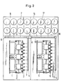
- FIG. 2 shows a converter constructed from two converter modules.
- two converter modules 1 and 11 with electrical module connections 2 and 12 can be seen.
- the capacitor bank of the DC voltage intermediate circuit of the converter is divided into two partial capacitor banks 6, 16 each having the same capacity and dielectric strength, which are each constructed from a plurality of individual capacitors 7, 17.
- the partial capacitor batteries 6, 16 are spatially assigned directly to the converter modules 1, 11 and are located, for example, above the modules. Between the partial capacitor batteries 6, 16 and the converter modules 1, 11, horizontal connecting rail systems 5, 15 are arranged, which are assembled with the vertical connecting rail systems 4, 14 and form a common electrical connecting rail system 3, 13 with them.
- the partial capacitor banks 6, 16 are each contacted to the horizontal connecting rail system 5, 15 via electrical capacitor connections 9, 19.
- the individual electrical connecting rail systems 3, 13 are joined together by means of an electrical coupling 8, which brings the horizontal connecting rail system 5 assigned to the converter module 1 into contact with the horizontal connecting rail system 15 assigned to the converter module 11.
- the converter shown in FIG. 2 can be expanded as desired by placing further converter modules directly next to the two existing modules 1, 11.
- Each additional converter module also has a partial capacitor bank that is spatially assigned to it and its own electrical connection rail system that is assigned to it, consisting of a vertical and a horizontal connection rail system.
- connection rail systems For the electrical contacting of the connection rail systems, further electrical couplings are used which connect the horizontal connection rail systems of adjacent converter modules with one another.
- the modules for example: a four-quadrant controller, a conventional rectifier or a DC voltage controller
- the load connection for example a conventional inverter
- the horizontal connecting rail system also contains feed lines and load connection lines in addition to the DC link lines.
- this is also not excluded and makes sense, for example, when two converter modules of the same type work in parallel, for example when two rectifiers with one and the same supply lines are connected are connected and work on the same DC link.
- one rectifier can be supplied via the base point of the vertical connecting rail system and the other rectifier can be supplied via the horizontal connecting rail system.
- the modules are fed in as well as the load connection via the horizontal connecting rail system, which accordingly also contains supply lines and load connection lines in addition to the DC link lines.
- the complete electrical connection of a module takes place via the respective vertical connecting rail systems from the horizontal connecting rail system in the sense of a bus system. It is sufficient if the horizontal connecting rail system is connected to the network and the load at one of its two ends.
- FIG. 3 shows the electrical circuit diagram of a converter constructed from four converter modules as a further exemplary embodiment.
- two four-quadrant actuators 1, 11 and two inverters 21, 31 are provided as converter modules.
- the four-quadrant actuators 1 and 11 are connected on the input side to feed lines 40, 41 and 42, 43 and on the output side to DC link lines 44, 45 and 46, 47.
- the lines 44 and 46 and 45 and 47 are each connected to one another.
- a capacitor bank 20 of the DC link and a suction circuit 10 consististing of a choke and a capacitor
- the inverters 21 and 31 are connected on the input side to the DC link lines 44, 45 and 46, 47 and on the output side to three-phase load connection lines 48, 49, 50 and 51, 52, 53.
- the converter is preferably used as a traction converter for feeding three-phase asynchronous machines with variable frequency and voltage (see, for example, BBC publication no. DVK 1047 81D, electric universal locomotive E 120 of the DB).
- the electrical connecting rail systems which are individual to the individual converter modules 1, 11, 21, 31 each have vertical connecting rail systems 4, 14, 24, 34 and horizontal ones Connection rail systems 5, 15, 25, 35, wherein the horizontal connection rails 5 and 15, 15 and 25 and 25 and 35 are electrically contacted with one another by means of electrical couplings 8, 18, 28.
- the electrical module connections which are arranged vertically in a row and come into contact with the vertical connecting rail systems 4, 14, 24, 34 are designated by numbers 2, 12, 22, 32.
- the individual electrical capacitor connections between the partial capacitor banks 6, 16, 26, 36 and the horizontal connecting rail systems 5, 15, 25, 35 are indicated.
- the feed (see feed lines 40 to 43 according to FIG. 3) of the four-quadrant actuators 1, 11 takes place via the base points of the vertical connecting rail systems 4, 14, while the load connections (see three-phase load connection lines 48 to 53 according to 3) with the base points of the vertical connecting rail systems 24, 34 are contacted.
- the horizontal connecting rail system consisting of components 5, 15, 25, 35 only contains the DC link lines (see DC link lines 44 to 47 according to FIG. 3).
- the horizontal connecting rail system consisting of components 5, 15, 25, 35 contains both the DC link lines 44 to 47 and the feed lines 40 to 43 and the three-phase load connection lines 48 to 53.
- the vertical ones Connection rail systems 4, 14, 24, 34 tap the rails required for the associated converter module in order to make contact with the electrical module connections.
- the suction circuit 10 according to FIG. 3 can be implemented by a suction circuit module 30 which is arranged in a row next to the converter modules.
- This suction circuit module 30 also has a horizontal connecting rail system 54, which is contacted via an electrical coupling 38 with the horizontal connecting rail system 35 of the adjacent module 31.
- the choke and the capacitor of the suction circuit 10 are connected to the DC voltage intermediate circuit lines of the horizontal connecting rail system 54.
- partial capacitor banks can also be arranged below the converter modules, although the horizontal connecting rail systems must always be arranged between partial capacitor banks and modules.
Landscapes
- Engineering & Computer Science (AREA)
- Power Engineering (AREA)
- Dc-Dc Converters (AREA)
- Power Conversion In General (AREA)
- Rectifiers (AREA)
- Details Of Television Scanning (AREA)
- Inverter Devices (AREA)
- Data Exchanges In Wide-Area Networks (AREA)
- Input Circuits Of Receivers And Coupling Of Receivers And Audio Equipment (AREA)
Applications Claiming Priority (4)
| Application Number | Priority Date | Filing Date | Title |
|---|---|---|---|
| DE4013820 | 1990-04-30 | ||
| DE4013820 | 1990-04-30 | ||
| DE4020026A DE4020026A1 (de) | 1990-04-30 | 1990-06-23 | Stromrichteranlage mit gleichspannungszwischenkreis und stromrichtermodulen |
| DE4020026 | 1990-06-23 |
Publications (3)
| Publication Number | Publication Date |
|---|---|
| EP0455120A2 true EP0455120A2 (fr) | 1991-11-06 |
| EP0455120A3 EP0455120A3 (en) | 1992-03-25 |
| EP0455120B1 EP0455120B1 (fr) | 1994-08-17 |
Family
ID=25892703
Family Applications (1)
| Application Number | Title | Priority Date | Filing Date |
|---|---|---|---|
| EP91106569A Expired - Lifetime EP0455120B1 (fr) | 1990-04-30 | 1991-04-24 | Arrangement de convertisseur de courant à circuit intermédiaire continu et modules convertisseurs |
Country Status (4)
| Country | Link |
|---|---|
| EP (1) | EP0455120B1 (fr) |
| AT (1) | ATE110195T1 (fr) |
| DE (2) | DE4020026A1 (fr) |
| ES (1) | ES2061107T3 (fr) |
Cited By (1)
| Publication number | Priority date | Publication date | Assignee | Title |
|---|---|---|---|---|
| WO1995008864A1 (fr) * | 1993-09-22 | 1995-03-30 | Honeywell Ag | Convertisseur |
Families Citing this family (7)
| Publication number | Priority date | Publication date | Assignee | Title |
|---|---|---|---|---|
| DE4126831C2 (de) * | 1991-08-14 | 1994-11-03 | Abb Patent Gmbh | Stromschienensystem für Stromrichter |
| DE4210657C2 (de) * | 1992-03-31 | 2001-06-07 | Moeller Gmbh | Einschub-Niederspannungsschaltanlage zur Abgabe oder Verteilung elektrischer Energie |
| DE4419467A1 (de) * | 1994-06-04 | 1995-12-07 | Bernd Jonatat | Spannungswandler zur Stromversorgung für elektrische Geräte |
| DE19833491A1 (de) * | 1998-07-24 | 2000-02-03 | Siemens Ag | Niederinduktive Verschienung für einen Dreipunkt-Phasenbaustein |
| DE19851161A1 (de) * | 1998-11-06 | 2000-05-11 | Abb Daimler Benz Transp | Stromrichtergerät mit Gleich- und Wechselspannungsverschienung |
| DE102004062169A1 (de) * | 2004-12-17 | 2006-07-13 | Siemens Ag | Schaltanlage |
| DE102012008550B4 (de) | 2011-05-27 | 2020-03-26 | Sew-Eurodrive Gmbh & Co Kg | Stromschienenteil |
Family Cites Families (2)
| Publication number | Priority date | Publication date | Assignee | Title |
|---|---|---|---|---|
| JPS614172A (ja) * | 1984-06-18 | 1986-01-10 | ファナック株式会社 | 交流電動機制御盤 |
| DE3802593A1 (de) * | 1988-01-29 | 1989-08-10 | Heidelberger Druckmasch Ag | Umrichter mit gleichspannungs-zwischenkreis |
-
1990
- 1990-06-23 DE DE4020026A patent/DE4020026A1/de not_active Withdrawn
-
1991
- 1991-04-24 AT AT91106569T patent/ATE110195T1/de not_active IP Right Cessation
- 1991-04-24 EP EP91106569A patent/EP0455120B1/fr not_active Expired - Lifetime
- 1991-04-24 ES ES91106569T patent/ES2061107T3/es not_active Expired - Lifetime
- 1991-04-24 DE DE59102538T patent/DE59102538D1/de not_active Expired - Fee Related
Cited By (1)
| Publication number | Priority date | Publication date | Assignee | Title |
|---|---|---|---|---|
| WO1995008864A1 (fr) * | 1993-09-22 | 1995-03-30 | Honeywell Ag | Convertisseur |
Also Published As
| Publication number | Publication date |
|---|---|
| ATE110195T1 (de) | 1994-09-15 |
| DE4020026A1 (de) | 1991-10-31 |
| DE59102538D1 (de) | 1994-09-22 |
| EP0455120B1 (fr) | 1994-08-17 |
| ES2061107T3 (es) | 1994-12-01 |
| EP0455120A3 (en) | 1992-03-25 |
Similar Documents
| Publication | Publication Date | Title |
|---|---|---|
| EP1101277B1 (fr) | Systeme de barres conductrices a basse induction pour module de phase a trois points | |
| DE60025865T2 (de) | Halbleitervorrichtung und elektrische Stromwandlungsvorrichtung | |
| DE4232763C2 (de) | Aufbau eines Wechselrichters, insbesondere eines 3-Punkt-Wechselrichters | |
| DE3609065C2 (fr) | ||
| EP0677916B1 (fr) | Ensemble convertisseur de puissance avec semi-conducteurs de puissance et circuit à courant continu refroidis par liquide ou par air | |
| EP0299275A1 (fr) | Ensemble convertisseur de puissance pour le couplage de deux types de réseaux haute-tension d'alimentation en courant triphasé | |
| EP3180850B1 (fr) | Circuit faiblement inductif d'un convertisseur | |
| EP0720787B1 (fr) | Convertisseur | |
| DE102018200712A1 (de) | Wandlervorrichtung elektrischer Leistung, Solarenergie-Aufbereitungssystem, Stromspeichersystem, unterbrechungsfreies Leistungsversorgungssystem, Windenergieerzeugungssystem und Motorantriebssystem | |
| DE102021211409A1 (de) | Inverteraufbau eines Elektronikmoduls für einen Elektroantrieb eines Fahrzeugs | |
| DE102020006207A1 (de) | Motorantriebsvorrichtung mit Glättungskondensatoreinheit und Beschaltungskondensator | |
| EP3404818A1 (fr) | Dispositif de semi-conducteurs | |
| EP0455120B1 (fr) | Arrangement de convertisseur de courant à circuit intermédiaire continu et modules convertisseurs | |
| EP0743744B1 (fr) | Convertisseur de courant | |
| DE9403108U1 (de) | Niederinduktive Hochstromverschienung für Stromrichtermodule | |
| EP0796757A2 (fr) | Fault tolerant motor drive power converter | |
| EP0519305B1 (fr) | Module de convertisseur | |
| WO2023006371A1 (fr) | Barre omnibus cc pour connexion électrique à une liaison cc d'un convertisseur de puissance, ensemble comprenant une barre omnibus cc et un convertisseur de puissance, et armoire de distribution | |
| DE102023209029B4 (de) | Traktionsnetz für ein Kraftfahrzeug | |
| DE102023204435B3 (de) | Halbbrückenanordnung eines Inverters eines Elektroantriebs eines Fahrzeugs | |
| DE29805943U1 (de) | Niederinduktive Verschienung zweier mehrlagiger Stromschienenanordnungen für Stromrichter | |
| WO2010034404A2 (fr) | Circuit et procédé de fabrication dudit circuit | |
| EP3834591A1 (fr) | Agencement de circuit intermédiaire et onduleur | |
| DE102021207309A1 (de) | Inverteraufbau eines Elektronikmoduls für einen Elektroantrieb eines Fahrzeugs | |
| DE3012244C2 (de) | Stromzwischenkreis-Umrichter |
Legal Events
| Date | Code | Title | Description |
|---|---|---|---|
| PUAI | Public reference made under article 153(3) epc to a published international application that has entered the european phase |
Free format text: ORIGINAL CODE: 0009012 |
|
| AK | Designated contracting states |
Kind code of ref document: A2 Designated state(s): AT BE CH DE ES FR GB IT LI SE |
|
| PUAL | Search report despatched |
Free format text: ORIGINAL CODE: 0009013 |
|
| AK | Designated contracting states |
Kind code of ref document: A3 Designated state(s): AT BE CH DE ES FR GB IT LI SE |
|
| 17P | Request for examination filed |
Effective date: 19920717 |
|
| 17Q | First examination report despatched |
Effective date: 19940125 |
|
| GRAA | (expected) grant |
Free format text: ORIGINAL CODE: 0009210 |
|
| AK | Designated contracting states |
Kind code of ref document: B1 Designated state(s): AT BE CH DE ES FR GB IT LI SE |
|
| REF | Corresponds to: |
Ref document number: 110195 Country of ref document: AT Date of ref document: 19940915 Kind code of ref document: T |
|
| ITF | It: translation for a ep patent filed | ||
| REF | Corresponds to: |
Ref document number: 59102538 Country of ref document: DE Date of ref document: 19940922 |
|
| ET | Fr: translation filed | ||
| GBT | Gb: translation of ep patent filed (gb section 77(6)(a)/1977) |
Effective date: 19940831 |
|
| REG | Reference to a national code |
Ref country code: ES Ref legal event code: FG2A Ref document number: 2061107 Country of ref document: ES Kind code of ref document: T3 |
|
| EAL | Se: european patent in force in sweden |
Ref document number: 91106569.6 |
|
| PLBE | No opposition filed within time limit |
Free format text: ORIGINAL CODE: 0009261 |
|
| STAA | Information on the status of an ep patent application or granted ep patent |
Free format text: STATUS: NO OPPOSITION FILED WITHIN TIME LIMIT |
|
| 26N | No opposition filed | ||
| PGFP | Annual fee paid to national office [announced via postgrant information from national office to epo] |
Ref country code: SE Payment date: 19980211 Year of fee payment: 8 |
|
| PGFP | Annual fee paid to national office [announced via postgrant information from national office to epo] |
Ref country code: BE Payment date: 19980212 Year of fee payment: 8 |
|
| PGFP | Annual fee paid to national office [announced via postgrant information from national office to epo] |
Ref country code: CH Payment date: 19980223 Year of fee payment: 8 Ref country code: GB Payment date: 19980223 Year of fee payment: 8 |
|
| PGFP | Annual fee paid to national office [announced via postgrant information from national office to epo] |
Ref country code: ES Payment date: 19980429 Year of fee payment: 8 |
|
| PG25 | Lapsed in a contracting state [announced via postgrant information from national office to epo] |
Ref country code: GB Free format text: LAPSE BECAUSE OF NON-PAYMENT OF DUE FEES Effective date: 19990424 |
|
| PG25 | Lapsed in a contracting state [announced via postgrant information from national office to epo] |
Ref country code: SE Free format text: LAPSE BECAUSE OF NON-PAYMENT OF DUE FEES Effective date: 19990425 |
|
| PG25 | Lapsed in a contracting state [announced via postgrant information from national office to epo] |
Ref country code: ES Free format text: THE PATENT HAS BEEN ANNULLED BY A DECISION OF A NATIONAL AUTHORITY Effective date: 19990426 |
|
| PG25 | Lapsed in a contracting state [announced via postgrant information from national office to epo] |
Ref country code: LI Free format text: LAPSE BECAUSE OF NON-PAYMENT OF DUE FEES Effective date: 19990430 Ref country code: CH Free format text: LAPSE BECAUSE OF NON-PAYMENT OF DUE FEES Effective date: 19990430 Ref country code: BE Free format text: LAPSE BECAUSE OF NON-PAYMENT OF DUE FEES Effective date: 19990430 |
|
| BERE | Be: lapsed |
Owner name: ABB PATENT G.M.B.H. Effective date: 19990430 |
|
| GBPC | Gb: european patent ceased through non-payment of renewal fee |
Effective date: 19990424 |
|
| REG | Reference to a national code |
Ref country code: CH Ref legal event code: PL |
|
| EUG | Se: european patent has lapsed |
Ref document number: 91106569.6 |
|
| REG | Reference to a national code |
Ref country code: FR Ref legal event code: TP |
|
| REG | Reference to a national code |
Ref country code: ES Ref legal event code: FD2A Effective date: 20010604 |
|
| PGFP | Annual fee paid to national office [announced via postgrant information from national office to epo] |
Ref country code: DE Payment date: 20030423 Year of fee payment: 13 |
|
| PGFP | Annual fee paid to national office [announced via postgrant information from national office to epo] |
Ref country code: FR Payment date: 20030827 Year of fee payment: 15 |
|
| PG25 | Lapsed in a contracting state [announced via postgrant information from national office to epo] |
Ref country code: FR Free format text: LAPSE BECAUSE OF NON-PAYMENT OF DUE FEES Effective date: 20031231 |
|
| REG | Reference to a national code |
Ref country code: FR Ref legal event code: ST |
|
| PG25 | Lapsed in a contracting state [announced via postgrant information from national office to epo] |
Ref country code: DE Free format text: LAPSE BECAUSE OF NON-PAYMENT OF DUE FEES Effective date: 20041103 |
|
| PG25 | Lapsed in a contracting state [announced via postgrant information from national office to epo] |
Ref country code: IT Free format text: LAPSE BECAUSE OF NON-PAYMENT OF DUE FEES;WARNING: LAPSES OF ITALIAN PATENTS WITH EFFECTIVE DATE BEFORE 2007 MAY HAVE OCCURRED AT ANY TIME BEFORE 2007. THE CORRECT EFFECTIVE DATE MAY BE DIFFERENT FROM THE ONE RECORDED. Effective date: 20050424 |
|
| PGFP | Annual fee paid to national office [announced via postgrant information from national office to epo] |
Ref country code: AT Payment date: 20100415 Year of fee payment: 20 |