EP0455355B1 - Haltevorrichtung für Triebwerke - Google Patents
Haltevorrichtung für Triebwerke Download PDFInfo
- Publication number
- EP0455355B1 EP0455355B1 EP91303058A EP91303058A EP0455355B1 EP 0455355 B1 EP0455355 B1 EP 0455355B1 EP 91303058 A EP91303058 A EP 91303058A EP 91303058 A EP91303058 A EP 91303058A EP 0455355 B1 EP0455355 B1 EP 0455355B1
- Authority
- EP
- European Patent Office
- Prior art keywords
- arms
- structures
- mounting assembly
- location
- engine
- Prior art date
- Legal status (The legal status is an assumption and is not a legal conclusion. Google has not performed a legal analysis and makes no representation as to the accuracy of the status listed.)
- Expired - Lifetime
Links
- 230000033001 locomotion Effects 0.000 claims description 28
- 238000002955 isolation Methods 0.000 claims description 14
- 230000006835 compression Effects 0.000 claims description 13
- 238000007906 compression Methods 0.000 claims description 13
- 230000005540 biological transmission Effects 0.000 claims description 7
- 230000000452 restraining effect Effects 0.000 claims 2
- 229920001971 elastomer Polymers 0.000 description 8
- 239000000806 elastomer Substances 0.000 description 8
- 230000000712 assembly Effects 0.000 description 7
- 238000000429 assembly Methods 0.000 description 7
- 239000012530 fluid Substances 0.000 description 5
- 239000002184 metal Substances 0.000 description 5
- 230000008901 benefit Effects 0.000 description 4
- 239000000463 material Substances 0.000 description 4
- 230000003068 static effect Effects 0.000 description 3
- 238000010276 construction Methods 0.000 description 2
- 239000013536 elastomeric material Substances 0.000 description 2
- 238000009434 installation Methods 0.000 description 2
- 230000009257 reactivity Effects 0.000 description 2
- 238000010008 shearing Methods 0.000 description 2
- 125000006850 spacer group Chemical group 0.000 description 2
- 230000009471 action Effects 0.000 description 1
- 230000004075 alteration Effects 0.000 description 1
- 238000004458 analytical method Methods 0.000 description 1
- 230000008859 change Effects 0.000 description 1
- 230000000295 complement effect Effects 0.000 description 1
- 238000013016 damping Methods 0.000 description 1
- 238000004519 manufacturing process Methods 0.000 description 1
- 238000000034 method Methods 0.000 description 1
- 230000004048 modification Effects 0.000 description 1
- 238000012986 modification Methods 0.000 description 1
- 229910001220 stainless steel Inorganic materials 0.000 description 1
- 239000010935 stainless steel Substances 0.000 description 1
- 230000000007 visual effect Effects 0.000 description 1
- 238000005303 weighing Methods 0.000 description 1
Images



Classifications
-
- B—PERFORMING OPERATIONS; TRANSPORTING
- B64—AIRCRAFT; AVIATION; COSMONAUTICS
- B64D—EQUIPMENT FOR FITTING IN OR TO AIRCRAFT; FLIGHT SUITS; PARACHUTES; ARRANGEMENT OR MOUNTING OF POWER PLANTS OR PROPULSION TRANSMISSIONS IN AIRCRAFT
- B64D27/00—Arrangement or mounting of power plants in aircraft; Aircraft characterised by the type or position of power plants
- B64D27/40—Arrangements for mounting power plants in aircraft
- B64D27/404—Suspension arrangements specially adapted for supporting vertical loads
Definitions
- the present invention provides a heavy duty mounting assembly particularly suited for isolating noise vibrations between two spaced structures, such as between the cabin of an aircraft and a high-thrust turbine engine.
- the mounting assembly includes a pair of arms disposed in spaced relation alongside one another between the two structures. Means is provided for making a torsional connection between the two arms to restrain motion relative to one another about an axis A-A extending transverse to the arms at a first location. Means is also provided for mounting the arms to one of the structures in a manner permitting the arms to pivot about axis A-A either in unison or independently of one another. Means is provided for connecting the arms to the other of the two structures at a second location spaced from said axis.
- the mounting assembly is characterized by a main vibration isolation connection between the arms and one of the structures being provided at a third location spaced from the pivot axis A-A whereby the structures are connected together in a manner that minimizes the transmission of vibrations between them.
- the elastomeric bearings are designed to be very stiff radially so as to be able to carry their share of vertical load without over strain.
- the isolator pad can be made relatively large in length and width for low compression stress, and thick for low compression strains, without compromising spring rate.
- the low compression stress also allows the use of a soft (low modulus) elastomer, which provides lower set and drift, less hysteresis damping, and a lower dynamic-to-static stiffness ratio. The result is increased service life, better vibration isolation, and less engine motion than other concepts having the same dynamic spring rates could provide.
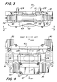
- lateral auxiliary elastomeric pad means are provided between the frame arms and the depending base flanges 14 and 16.
- the lateral auxiliary pad means includes a pair of pads 30 and 32 engaging the arm extensions 24a and 26a forward of the torque tube 28 and a pair of pads 34 and 36 engaging the arm surfaces 24b and 26b adjacent the tie brace 31.
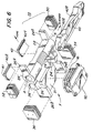
- the pads 30, 32, 34 and 36 are provided by laminated elastomeric bearings composed of alternating layers of elastic and inelastic materials, such layers of elastomeric material bonded to and between flat metal shims.
- the present invention now provides a turbine engine mounting assembly which is well suited for heavy duty applications and for applications requiring improved lateral and vertical vibration isolation without as much allowed engine motion as is available with known mounts. Since the mounting bracket assembly utilizes known materials and state of the art manufacturing techniques, it can be designed to meet a variety of operational requirements, yet can be assembled in a straightforward manner and refurbished readily, if necessary.
- the arms extend in parallel relation from the torque tube, but in some applications they may converge or diverge.
- the ends of the arms can be interconnected by tie means, other than the metal tie brace shown, provided the requisite function is realized.
- the frame also need not in all instances be pivotally supported by the torque tube bearings, but could be supported pivotally at a location separated from the torque tube axis.
- the torque tube is, however, required. While the hanger lugs connect to the arms between the torque tube and main isolator pad, there may be applications where the arms could be extended fore or aft of either the torque tube and the main isolator pad and attachment made to the arm extensions. Accordingly, while the embodiment disclosed is the best mode contemplated by the applicants at this time, it is not to be regarded as limiting.
Landscapes
- Engineering & Computer Science (AREA)
- Aviation & Aerospace Engineering (AREA)
- Vibration Prevention Devices (AREA)
Claims (8)
- Haltevorrichtung (10) zum Verbinden und Schwingungsisolieren zweier beabstandeter Strukturen (S, E), mit
einem Paar Arme (24, 26), die beabstandet und längs zueinander zwischen den Strukturen (S, E) angeordnet sind,
Mitteln (28, 31) zum Schaffen einer Torsionsverbindung zwischen den Armen (24, 26), um eine Bewegung relativ zueinander um eine Achse (A-A) zu hemmen, die sich quer zu den Armen (24, 26) an einer ersten Stelle erstreckt, Mitteln (12) zum Befestigen der Arme (24, 26) an der einen Struktur (S) in einer Weise, daß die Arme (24, 26) um die Achse (A-A) entweder miteinander oder unabhängig voneinander schwenkbar sind,
Mitteln (18, 20) zum Verbinden der Arme (24, 26) an der anderen Struktur (E) an einer zweiten Stelle, die von der Achse (A-A) beabstandet ist,
gekennzeichnet durch
Mittel (50) zur Hauptvibrationsisolationsverbindung zwischen den Armen (24, 26) und der einen Struktur (S) an einer dritten Stelle, die von der Schwenkachse (A-A) beabstandet ist,
wobei die Strukturen (S, E) in einer Weise miteinander verbunden sind, daß die Übertragung von Schwingungen zwischen ihnen minimiert ist. - Haltevorrichtung nach Anspruch 1, ferner gekennzeichnet durch Flanschmittel (14, 16) an den Mitteln (12) zur Befestigung der Arme (24, 26) an der einen Struktur (S), die sich längs von wenigstens Teilen der Arme erstreckt, sowie Hilfsvibrationsisolationsmittel (30, 32, 34, 36), die zwischen den Armbereichen und den Flanschmitteln angeordnet sind, um die Bewegung der Arme längs der Schwenkachse (A-A) zu hemmen, während sie die Schwenkbewegung der Arme um die Schwenkachse herum aufnehmen.
- Haltevorrichtung nach Anspruch 2, ferner gekennzeichnet durch Hilfssschwingungsisolationsmittel (30, 34; 32, 36), die derart angeordnet sind, daß sich ihre elastische Mitte durch die zweite Stelle erstreckt.
- Haltevorrichtung nach Anspruch 2 oder 3, dadurch gekennzeichnet, daß sich die Flanschmittel (14, 16) in einer beabstandeten parallelen benachbarten Beziehung entlang gegenüberliegender Seiten der Arme erstrecken, wobei die Hilfsschwingungsisolationsmittel ein Paar (30, 34; 32, 36) federnde Kissen aufweisen, die zwischen jedem Arm (24, 26) und seinen benachbarten Flanschmitteln angeordnet sind.
- Haltevorrichtung nach einem der Ansprüche 1 bis 4, dadurch gekennzeichnet, daß die Mittel zur Hauptschwingungsisolationsverbindung Mittel (31, 50, 52) aufweisen, um die Arme mit der einen Struktur in einer Weise federnd zu verbinden, daß eine wesentliche Relativbewegung sowohl zwischen den Armen als auch zwischen den Armen und der einen Struktur an der dritten Stelle verhindert wird.
- Haltevorrichtung nach Anspruch 5, dadurch gekennzeichnet, daß die Mittel zur federnden Verbindung der Arme ein Bindeglied (31) aufweisen, das die Arme miteinander an der dritten Stelle verbindet, eine federnde Druckkissenanordnung (50), die mit dem Bindeglied in Eingriff ist, und ein Kappenmittel (52), das mit dem federnden Druckkissen in Eingriff ist, um es mit der einen Struktur zu verbinden, wobei die Bewegung der Arme, die von der einen Struktur weggerichtet ist, unter Druck von dem federnden Druckkissen aufgenommen wird.
- Haltevorrichtung nach einem der Ansprüche 1 bis 6, dadurch gekennzeichnet, daß die Arme (24, 26), die Drehverbindungsmittel (28) und die Hauptschwingungsisolationsverbindung (50) zusammenwirken, um einen offenen Rahmen (F) zu bilden, der zwischen den Strukturen (S, E) angeordnet ist, und daß die Mittel zum Befestigen der Arme an der einen Struktur eine elastomere Lageranordnung (40a, 40b, 42a, 42b) aufweisen.
- Haltevorrichtung nach einem der Ansprüche 1 bis 5, dadurch gekennzeichnet, daß sich die Arme (24, 26) beabstandet erstrecken und an der ersten Stelle mittels eines Drehmomentrohrs (28) verbunden sind, das die Drehverbindungsmittel schafft; und daß die Mittel für die Hauptschwingungsisolationsverbindung ein Bindeglied (31) aufweisen, das die Arme an der dritten Stelle verbindet, ein federndes Druckkissen (50), das mit dem Bindeglied in Eingriff ist, und ein Kappenmittel (52), welches das Kissen mit der einen Struktur (S) verbindet, wobei die Armbewegung unter Druck vom federnden Kissen aufgenommen ist.
Applications Claiming Priority (2)
| Application Number | Priority Date | Filing Date | Title |
|---|---|---|---|
| US514071 | 1990-04-25 | ||
| US07/514,071 US5108045A (en) | 1990-04-25 | 1990-04-25 | Engine mounting assembly |
Publications (2)
| Publication Number | Publication Date |
|---|---|
| EP0455355A1 EP0455355A1 (de) | 1991-11-06 |
| EP0455355B1 true EP0455355B1 (de) | 1994-11-30 |
Family
ID=24045682
Family Applications (1)
| Application Number | Title | Priority Date | Filing Date |
|---|---|---|---|
| EP91303058A Expired - Lifetime EP0455355B1 (de) | 1990-04-25 | 1991-04-08 | Haltevorrichtung für Triebwerke |
Country Status (4)
| Country | Link |
|---|---|
| US (1) | US5108045A (de) |
| EP (1) | EP0455355B1 (de) |
| CA (1) | CA2038621C (de) |
| DE (1) | DE69105345T2 (de) |
Families Citing this family (23)
| Publication number | Priority date | Publication date | Assignee | Title |
|---|---|---|---|---|
| US6022600A (en) * | 1992-04-24 | 2000-02-08 | Lord Corporation | High-temperature fluid mounting |
| US5351930A (en) * | 1992-08-11 | 1994-10-04 | Lord Corporation | Mounting for engines and the like |
| FR2738034B1 (fr) * | 1995-08-23 | 1997-09-19 | Snecma | Dispositif de suspension d'un turbopropulseur |
| US5687948A (en) * | 1995-09-26 | 1997-11-18 | Lord Corporation | Vibration isolation system including a passive tuned vibration absorber |
| US6065742A (en) * | 1996-09-13 | 2000-05-23 | Lord Corporation | Multi-directional tuned vibration absorber |
| US5845236A (en) * | 1996-10-16 | 1998-12-01 | Lord Corporation | Hybrid active-passive noise and vibration control system for aircraft |
| US5957440A (en) * | 1997-04-08 | 1999-09-28 | Lord Corporation | Active fluid mounting |
| US6113030A (en) * | 1997-11-17 | 2000-09-05 | Lord Corporation | Readily changeable isolator and method of assembly thereof |
| US6328293B1 (en) | 1998-09-18 | 2001-12-11 | Lord Corporation | Multi-linkage suspension system including outboard isolators |
| US7104306B2 (en) * | 2004-06-14 | 2006-09-12 | The Boeing Company | Cast unitized primary truss structure and method |
| GB0507721D0 (en) * | 2005-04-16 | 2005-05-25 | Rolls Royce Plc | Gas turbine engine mounting arrangement |
| WO2008091376A2 (en) * | 2006-07-25 | 2008-07-31 | Lord Corporation | Tiltrotor aircraft drivelink |
| FR2914907B1 (fr) * | 2007-04-16 | 2009-10-30 | Snecma Sa | Suspension souple avec peigne pour turbomoteur |
| US7966921B1 (en) * | 2009-04-01 | 2011-06-28 | The United States Of America As Represented By The Secretary Of The Navy | Aircraft wing-pylon interface mounting apparatus |
| FR2947528B1 (fr) * | 2009-07-03 | 2011-06-24 | Airbus Operations Sas | Systeme d'attache d'un moteur a helices |
| US7784773B1 (en) | 2009-08-04 | 2010-08-31 | Itt Manufacturing Enterprises, Inc. | Isolator useful for in-line mounting with a strut |
| US9174739B2 (en) | 2014-01-13 | 2015-11-03 | The Boeing Company | Active vibration control system |
| US9617918B2 (en) * | 2014-01-13 | 2017-04-11 | The Boeing Company | Bracket for mounting/removal of actuators for active vibration control |
| US10161309B2 (en) | 2015-02-10 | 2018-12-25 | United Technologies Corporation | Thermally compliant fitting for high temperature tube applications |
| US10336459B2 (en) * | 2016-02-01 | 2019-07-02 | Bell Helicopter Textron Inc. | Clamped splines for aircraft engine mount assemblies |
| WO2018031548A1 (en) | 2016-08-08 | 2018-02-15 | Lord Corporation | Mounting systems, devices, and methods for aircraft engines |
| CN109592051A (zh) * | 2018-12-03 | 2019-04-09 | 江西洪都航空工业集团有限责任公司 | 一种发动机安装结构 |
| EP3663206B1 (de) * | 2018-12-06 | 2023-09-06 | AIRBUS HELICOPTERS DEUTSCHLAND GmbH | Befestigung zum aufhängen eines flugzeugtriebwerks |
Family Cites Families (12)
| Publication number | Priority date | Publication date | Assignee | Title |
|---|---|---|---|---|
| FR821528A (fr) * | 1936-08-07 | 1937-12-07 | D Aviat Louis Breguet Sa Des E | Suspension élastique des moteurs d'aéronefs |
| US2197081A (en) * | 1937-06-14 | 1940-04-16 | Transit Res Corp | Motor support |
| US2891743A (en) * | 1954-06-08 | 1959-06-23 | Textron Inc | Airplane engine suspension and mounts therefor |
| US3168270A (en) * | 1963-02-11 | 1965-02-02 | Cal Val Res & Dev Corp | Engine mount |
| US3288404A (en) * | 1964-08-24 | 1966-11-29 | Lord Corp | Engine mounting system |
| US3747879A (en) * | 1972-02-23 | 1973-07-24 | Gen Motors Corp | Engine mount |
| WO1985002596A1 (en) * | 1983-12-08 | 1985-06-20 | The Boeing Company | Aft engine mount |
| US4634081A (en) * | 1983-12-30 | 1987-01-06 | The Boeing Company | Aft engine mount with vibration isolators |
| US4717094A (en) * | 1986-05-19 | 1988-01-05 | The Boeing Company | Aircraft engine mount system with vibration isolators |
| US4725019A (en) * | 1986-08-11 | 1988-02-16 | The Boeing Company | Aircraft engine mount with vertical vibration isolation |
| US4805851A (en) * | 1987-08-10 | 1989-02-21 | Herbst Paul T | Turbine engine mounting bracket assembly |
| FR2638799B1 (fr) * | 1988-11-09 | 1991-01-25 | Hutchinson | Support elastique a raideurs anisotropes, notamment pour la suspension de carrosseries |
-
1990
- 1990-04-25 US US07/514,071 patent/US5108045A/en not_active Expired - Lifetime
-
1991
- 1991-03-19 CA CA002038621A patent/CA2038621C/en not_active Expired - Fee Related
- 1991-04-08 EP EP91303058A patent/EP0455355B1/de not_active Expired - Lifetime
- 1991-04-08 DE DE69105345T patent/DE69105345T2/de not_active Expired - Fee Related
Also Published As
| Publication number | Publication date |
|---|---|
| CA2038621A1 (en) | 1991-10-26 |
| DE69105345D1 (de) | 1995-01-12 |
| CA2038621C (en) | 2003-05-27 |
| US5108045A (en) | 1992-04-28 |
| DE69105345T2 (de) | 1995-04-27 |
| EP0455355A1 (de) | 1991-11-06 |
Similar Documents
| Publication | Publication Date | Title |
|---|---|---|
| EP0455355B1 (de) | Haltevorrichtung für Triebwerke | |
| US4725019A (en) | Aircraft engine mount with vertical vibration isolation | |
| US4805851A (en) | Turbine engine mounting bracket assembly | |
| EP1113959B1 (de) | Mehrlenkeraufhängungssystem mit aussenisolator | |
| EP0583158B1 (de) | Motorlager | |
| US6431530B1 (en) | Vertical liquid inertia vibration isolator | |
| US5176339A (en) | Resilient pivot type aircraft mounting | |
| EP1115614B1 (de) | Flüssigkeitsgefüllter dämpfer mit einer flexiblen dämpfungsplatte | |
| EP0629791A1 (de) | Fluidumlager für Triebwerke oder dergleichen | |
| WO1992021912A1 (en) | Vibration isolation system | |
| CN100408910C (zh) | 可变刚度支撑件 | |
| JPS6249239B2 (de) | ||
| US7900873B2 (en) | Vibration isolation system | |
| EP1671047B1 (de) | Schwingungsdämpfungshalterung | |
| US4365771A (en) | Inplane nodalization system | |
| US11427308B2 (en) | Attachment of a landing gear | |
| US6871820B2 (en) | Aircraft engine mounting | |
| US5523530A (en) | Elastomeric acoustic insulator | |
| US3056569A (en) | Airplane engine suspension system | |
| EP2894098B1 (de) | Halter zur Montage/Demontage von Aktuatoren zur aktiven Vibrationssteuerung | |
| CA1142155A (en) | Inplane nodalization system | |
| US12227289B2 (en) | Rotorcraft provided with an airframe carried by a skid landing gear with zones for taking up variable forces | |
| US2794610A (en) | Resilient suspension of engines | |
| US20260088419A1 (en) | Battery mounting structure and battery pack for electric vehicle |
Legal Events
| Date | Code | Title | Description |
|---|---|---|---|
| PUAI | Public reference made under article 153(3) epc to a published international application that has entered the european phase |
Free format text: ORIGINAL CODE: 0009012 |
|
| AK | Designated contracting states |
Kind code of ref document: A1 Designated state(s): DE FR GB IT |
|
| 17P | Request for examination filed |
Effective date: 19920427 |
|
| 17Q | First examination report despatched |
Effective date: 19930623 |
|
| GRAA | (expected) grant |
Free format text: ORIGINAL CODE: 0009210 |
|
| AK | Designated contracting states |
Kind code of ref document: B1 Designated state(s): DE FR GB IT |
|
| ITF | It: translation for a ep patent filed | ||
| REF | Corresponds to: |
Ref document number: 69105345 Country of ref document: DE Date of ref document: 19950112 |
|
| ET | Fr: translation filed | ||
| PLBE | No opposition filed within time limit |
Free format text: ORIGINAL CODE: 0009261 |
|
| STAA | Information on the status of an ep patent application or granted ep patent |
Free format text: STATUS: NO OPPOSITION FILED WITHIN TIME LIMIT |
|
| 26N | No opposition filed | ||
| REG | Reference to a national code |
Ref country code: GB Ref legal event code: IF02 |
|
| PGFP | Annual fee paid to national office [announced via postgrant information from national office to epo] |
Ref country code: FR Payment date: 20020319 Year of fee payment: 12 |
|
| PGFP | Annual fee paid to national office [announced via postgrant information from national office to epo] |
Ref country code: GB Payment date: 20020403 Year of fee payment: 12 |
|
| PGFP | Annual fee paid to national office [announced via postgrant information from national office to epo] |
Ref country code: DE Payment date: 20020418 Year of fee payment: 12 |
|
| PG25 | Lapsed in a contracting state [announced via postgrant information from national office to epo] |
Ref country code: GB Free format text: LAPSE BECAUSE OF NON-PAYMENT OF DUE FEES Effective date: 20030408 |
|
| PG25 | Lapsed in a contracting state [announced via postgrant information from national office to epo] |
Ref country code: DE Free format text: LAPSE BECAUSE OF NON-PAYMENT OF DUE FEES Effective date: 20031101 |
|
| GBPC | Gb: european patent ceased through non-payment of renewal fee |
Effective date: 20030408 |
|
| PG25 | Lapsed in a contracting state [announced via postgrant information from national office to epo] |
Ref country code: FR Free format text: LAPSE BECAUSE OF NON-PAYMENT OF DUE FEES Effective date: 20031231 |
|
| REG | Reference to a national code |
Ref country code: FR Ref legal event code: ST |
|
| PG25 | Lapsed in a contracting state [announced via postgrant information from national office to epo] |
Ref country code: IT Free format text: LAPSE BECAUSE OF NON-PAYMENT OF DUE FEES;WARNING: LAPSES OF ITALIAN PATENTS WITH EFFECTIVE DATE BEFORE 2007 MAY HAVE OCCURRED AT ANY TIME BEFORE 2007. THE CORRECT EFFECTIVE DATE MAY BE DIFFERENT FROM THE ONE RECORDED. Effective date: 20050408 |