EP0455382B1 - Procédé pour régler l'épaisseur de la bande dans un laminoir de métal - Google Patents
Procédé pour régler l'épaisseur de la bande dans un laminoir de métal Download PDFInfo
- Publication number
- EP0455382B1 EP0455382B1 EP91303487A EP91303487A EP0455382B1 EP 0455382 B1 EP0455382 B1 EP 0455382B1 EP 91303487 A EP91303487 A EP 91303487A EP 91303487 A EP91303487 A EP 91303487A EP 0455382 B1 EP0455382 B1 EP 0455382B1
- Authority
- EP
- European Patent Office
- Prior art keywords
- stand
- speed
- thickness
- strip
- control signal
- Prior art date
- Legal status (The legal status is an assumption and is not a legal conclusion. Google has not performed a legal analysis and makes no representation as to the accuracy of the status listed.)
- Revoked
Links
- 238000000034 method Methods 0.000 title claims description 31
- 238000005096 rolling process Methods 0.000 title claims description 23
- 239000002184 metal Substances 0.000 title claims description 10
- 229910052751 metal Inorganic materials 0.000 title claims description 10
- 238000011144 upstream manufacturing Methods 0.000 claims description 14
- 230000008859 change Effects 0.000 claims description 13
- 239000003607 modifier Substances 0.000 claims description 9
- 238000005259 measurement Methods 0.000 claims description 7
- 230000004044 response Effects 0.000 description 8
- 238000005094 computer simulation Methods 0.000 description 6
- 230000009471 action Effects 0.000 description 4
- 238000005070 sampling Methods 0.000 description 4
- 238000012937 correction Methods 0.000 description 3
- 238000013461 design Methods 0.000 description 3
- 238000010586 diagram Methods 0.000 description 3
- 230000006872 improvement Effects 0.000 description 3
- XEEYBQQBJWHFJM-UHFFFAOYSA-N Iron Chemical compound [Fe] XEEYBQQBJWHFJM-UHFFFAOYSA-N 0.000 description 2
- 238000011217 control strategy Methods 0.000 description 2
- 230000003111 delayed effect Effects 0.000 description 2
- 238000012986 modification Methods 0.000 description 2
- 230000004048 modification Effects 0.000 description 2
- 230000009467 reduction Effects 0.000 description 2
- 230000004043 responsiveness Effects 0.000 description 2
- 230000001133 acceleration Effects 0.000 description 1
- 238000013459 approach Methods 0.000 description 1
- 230000005540 biological transmission Effects 0.000 description 1
- 238000004364 calculation method Methods 0.000 description 1
- 238000005097 cold rolling Methods 0.000 description 1
- 230000001276 controlling effect Effects 0.000 description 1
- 230000001186 cumulative effect Effects 0.000 description 1
- 230000007812 deficiency Effects 0.000 description 1
- 230000001419 dependent effect Effects 0.000 description 1
- 229910052742 iron Inorganic materials 0.000 description 1
- 230000007774 longterm Effects 0.000 description 1
- 230000010363 phase shift Effects 0.000 description 1
- 230000001105 regulatory effect Effects 0.000 description 1
- 238000004088 simulation Methods 0.000 description 1
- 230000001502 supplementing effect Effects 0.000 description 1
- 238000012360 testing method Methods 0.000 description 1
- 230000001052 transient effect Effects 0.000 description 1
- 238000013519 translation Methods 0.000 description 1
Images



Classifications
-
- B—PERFORMING OPERATIONS; TRANSPORTING
- B21—MECHANICAL METAL-WORKING WITHOUT ESSENTIALLY REMOVING MATERIAL; PUNCHING METAL
- B21B—ROLLING OF METAL
- B21B37/00—Control devices or methods specially adapted for metal-rolling mills or the work produced thereby
- B21B37/16—Control of thickness, width, diameter or other transverse dimensions
-
- G—PHYSICS
- G05—CONTROLLING; REGULATING
- G05D—SYSTEMS FOR CONTROLLING OR REGULATING NON-ELECTRIC VARIABLES
- G05D5/00—Control of dimensions of material
- G05D5/02—Control of dimensions of material of thickness, e.g. of rolled material
- G05D5/03—Control of dimensions of material of thickness, e.g. of rolled material characterised by the use of electric means
-
- B—PERFORMING OPERATIONS; TRANSPORTING
- B21—MECHANICAL METAL-WORKING WITHOUT ESSENTIALLY REMOVING MATERIAL; PUNCHING METAL
- B21B—ROLLING OF METAL
- B21B2275/00—Mill drive parameters
- B21B2275/02—Speed
- B21B2275/04—Roll speed
Definitions
- This invention relates generally to multi-stand metal rolling mills and, more particularly, to a method of improved control of strip thickness in such mills.
- Modern multi-stand cold rolling mills commonly employ a form of feed-forward gage control which acts between adjacent stands of such mills.
- a thickness gage situated between these stands measures strip thickness and sends a strip thickness data signal, with some inherent time delay, from the thickness gage to the downstream rolling stand.
- a control action is initiated, most commonly an adjustment to the upstream speed reference in proportion to the thickness change from an initial measurement, or from some nominal thickness. For example, if a strip's thickness increases by one percent from its initial thickness, then upon arrival of the thicker strip region at the downstream stand a one percent reduction of the initial upstream stand speed reference would be made.
- An objective of feed-forward control is to improve the uniformity of strip thickness out of the downstream stand.
- Control of the absolute strip thickness is the objective of later control action, such as feedback control based on final thickness measurements, and is not the subject of this invention.
- a method for controlling metal thickness is provided in a rolling mill having at least two mill stands and means for adjusting the stand rolling speed.
- the method of the present invention controls strip thickness leaving a downstream stand by measuring strip thickness with a thickness measuring means situated between stands.
- the thickness measurements are stored and then retrieved after a delay equal to the strip travel time between the thickness measuring means and the downstream stand.
- the instantaneous desired speed of the upstream stand is calculated as a function of the actual speed of the downstream stand, the planned speeds of both stands, the strip thickness of the strip increment arriving at the downstream stand, and its thickness change from the initial strip thickness.
- the reference to the upstream stand current regulator is adjusted as a function of the difference between the instantaneous desired speed and the actual measured speed of the upstream stand.
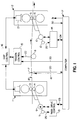
- FIG.1 shows in schematic form a typical pair of any two adjacent mill stands, such as might be employed in the implementation of the method of the present invention. It is to be understood that the depiction of FIG.1 is simplified to show only the essential elements which are pertinent to the present invention. Further, it is understood that the depiction of FIG. 1 may be any two adjacent stands of a multistand rolling mill.
- a workpiece 18 is passed through opposed workrolls 3 and 4 of a first upstream mill stand 1 and opposed workrolls 5 and 6 of a second downstream rolling mill stand 2 and passes through thickness sensing means 7 and over tension sensing means 8, both situated between the stands.
- Workrolls 3 and 4 are driven by motor 9 and workrolls 5 and 6 by motor 10.
- Speed sensors 11 and 12 are connected to motors 9 and 10, respectively, and provide speed feedback: 25 and 26 to main drive controls 13 and 14, respectively.
- Drive controls 13 and 14 maintain stand 1 and stand 2 rolling speeds at reference levels 23 and 24, respectively, determined by computer 17.
- thickness measurements 20 are made and transmitted to and stored sequentially in computer 17.
- FIG.2 illustrates essential elements of the main drive control 13 in simplified block diagram form.
- Speed reference 23 is compared with speed feedback 25 to produce speed error, Ve, which is operated on by the speed error or velocity error amplifier 27, to produce the current regulator reference Irs.
- the main drive power supply and motor armature circuit are shown combined in armature current regulator 28.
- the current regulator controls the main drive power supply so as to produce the desired armature current, I, which results in motor torque, Tm, in accordance with well known principles of motor control.
- the current reference modifier, dIr produced by the method of the present invention, is added to the current reference Irs to produce the modified current reference, Ir.
- Resulting armature current, I produces motor torque Tm which combines with load torque, Tl, to produce a corresponding acceleration ( ⁇ acc) and speed change dV.
- FIG.2 Certain elements of the present invention are shown in FIG.2 to illustrate its relation to the conventional main drive speed control.
- the stand 1 speed reference V1r is compared with measured stand speed V1 to produce the speed error Ve'.
- This is operated on by the controller 34 to provide the current reference modifier dIr which is added to the speed regulator current reference Irs to produce the modified current reference Ir.
- FIG.1 Several elements which are not part of the present invention have been included in FIG.1 to assist in complete understanding. It is useful to understand that the gap between opposed workrolls 5 and 6 of stand 2 is and must be adjustable. In older mills the roll gap is adjusted by screw 21 under the control of gap control 16. Alternatively, the gap may be adjusted by hydraulic cylinders as in many newer rolling mills.
- Tension control 15 receives a strip tension signal 22 from tension sensing means 8, compares it to the tension reference signal 33, then directs gap control 16 to adjust screw 21 so as to reduce the difference between signals 22 and 33. The action of these tension and gap control elements completes the gage changes initiated by the method of the present invention.
- Reference values to the many control equipments required to operate a multi-stand rolling mill are typically generated by a set-up computer 17, such as the Digital Equipment Corporation VAX-11-780 computer.
- the desired stand velocities 23 and 24 and the desired strip thickness 19, which are relevant to the present invention, are among information produced by computer 17.
- Other inputs not pertinent to the present invention are shown as carried over bus 30 and would include, as well known in the art, such elements as rolling schedule data, operator inputs, etc.
- Other outputs are shown as carried over bus 31.
- the method of the present invention differs from prior art not only in the manner in which the speed reference V1r is developed, but also in its use to develop the current reference modified, dIr.
- V1r is compared with the measured stand 1 speed V1 to produce a speed error Ve'.
- Ve' is operated on by a controller to develop the current reference modifier, dIr.
- that controller utilizes proportional and derivative functions of Ve' to produce the current reference modifier, dIr.
- the current reference modifier, dIr is added to the current reference, Irs, generated by the speed error amplifier 27, to produce the total current reference Ir.
- Td .02 - .03 seconds
- the method of the present invention can be applied in parallel with the prior art method. This would be useful in eliminating cumulative errors in the speed regulator. When so used, the present invention would act to produce those components of armature current which are required to correct for the speed regulator's slow response, as well as to correct stand 1 speed so as to maintain its proper relation to stand 2 speed.
- sampling frequency need be high enough only to satisfy the gage performance requirements. For example, tests indicated that good results in the sampled data form are obtained with thickness samples and current reference modifier calculations at 0.25 second intervals, although intervals of about 0.1 second were required to fully match continuous system results.
- FIG.3 illustrates a computer simulation of feed-forward gage control employing a prior art method to correct incoming strip thickness variations.
- a typical sequence of incoming thickness variations to stand 1 was chosen arbitrarily to illustrate the performance differences.
- Speed reference changes proportional to the gage changes entering stand 2 are applied to the stand 1 speed controller.
- Thickness measurements, i.e., gages, are sampled four times per second in this example.
- Trace 1 indicates thickness leaving stand 2.
- Trace 2 indicates V1r, the correct speed for stand 1 considering the incoming thickness changes and the speed of stand 2.
- Trace 3 indicates the actual speed of stand 1, which is seen to diverge significantly from the desired course indicated by trace 2.
- Thickness leaving stand 2 varied about .001 inch over the sample length.
- FIG.4 illustrates a computer simulation of an improved prior art method of feed-forward gage control employing compensation of the main drive dynamic response, as was suggested in the previously cited Fapiano et al article "Thickness Control in Cold Rolling".
- the responsiveness of stand 1 speed (trace 3) is clearly improved, but there is no significant reduction in thickness variation (trace 1) because the change in stand 2 speed has not been considered in generating the reference to the speed regulator.
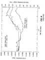
- FIG.5 illustrates the results of a computer simulation which repeats the conditions of FIG.3 and FIG.4 but employs the method of the present invention.
- Stand 1 speed follows the desired course (trace 2) more accurately and thickness variations leaving stand 2 are reduced about 50% compared with the prior art methods.
- the improvement results from the consideration of stand 2 speed changes, which are due largely to the tension-induced load changes, and, to a lesser extent, from the additional response improvement achieved by supplementing the speed regulator current reference, Irs, with the current reference modifier dIr, to achieve the desired speed at stand 1.
- the present invention is thus seen to eliminate the principal problem with previous methods of feed forward gage control, and in a manner which can be readily applied to both new and existing rolling mill gage control systems.
Landscapes
- Engineering & Computer Science (AREA)
- Physics & Mathematics (AREA)
- General Physics & Mathematics (AREA)
- Automation & Control Theory (AREA)
- Mechanical Engineering (AREA)
- Control Of Metal Rolling (AREA)
Claims (4)
- Procédé de réglage d'une épaisseur de métal dans un laminoir de métal comportant au moins deux trains de laminage (1, 2), chaque train de laminage comportant au moins une paire de cylindres de travail opposés (3, 4 ; 5, 6) pour réduire l'épaisseur d'une pièce à laminer en métal (18) passée entre eux, un moyen de détection d'épaisseur (7) pour détecter une épaisseur de bande entre des trains de laminage adjacents, un moyen (11, 12) pour détecter la vitesse de laminage de chaque train de laminage et un moyen de commande d'entraînement principal (13, 14) pour commander la vitesse du moteur d'entraînement principal et le courant d'induit, le procédé comprenant :(a) la mesure d'une épaisseur de bande selon des incréments successifs de longueurs de bande passant entre le premier train de laminage amont (1) et le second train de laminage aval (2) ;(b) lorsque chaque incrément successif de bande arrive au niveau du train de laminage, l'établissement d'un premier signal de commande (V1r) en fonction de la vitesse du second train de laminage, des vitesses de référence des premier et second trains de laminage, et des mesures d'épaisseur de bande ;(c) lorsque chaque incrément successif de bande arrive au niveau du second train de laminage, établissement d'un second signal de commande proportionnel à la différence entre la vitesse mesurée du premier train de laminage et ledit premier signal de commande ; et(d) modification de la vitesse du premier train de laminage en fonction du second signal de commande.
- Procédé selon la revendication 1, dans lequel ledit premier signal de commande est établi conformément à la relation :

V1r = vitesse de référence du train de laminage 1
H2 = épaisseur de bande d'entrée du train de laminage 2
H20 = valeur initiale de H2
dH2 = H2 - H20 = variation de l'épaisseur de bande entrant dans le train de laminage 2
V2 = vitesse du train de laminage 2
V1ro = vitesse de référence relative au train de laminage 1
V2ro = vitesse de référence relative au train de laminage 2. - Procédé selon la revendication 1, dans lequel le second signal de commande est établi conformément à la relation :

K = constante de gain proportionnelle
Td = dérivée ou constante de temps en avance
Tl = constante de temps en retard
s = opérateur d/dt
V1r = vitesse de référence du train de laminage 1
V1 = vitesse du train de laminage 1. - Procédé de réglage d'une épaisseur de métal dans un laminoir comportant au moins deux trains de laminage (1, 2), chaque train de laminage comportant au moins une paire de cylindres de travail opposés (3, 4 ; 5, 6) pour réduire l'épaisseur d'une pièce à laminer en métal (18) passée entre eux, un moyen de détection d'épaisseur (7) pour détecter une épaisseur de bande entre des trains de laminage adjacents, un moyen (11, 12) pour détecter la vitesse de laminage de chaque train de laminage et un moyen de commande d'entraînement principal (13, 14) pour commander la vitesse du moteur d'entraînement principal en commandant le courant d'induit d'entraînement principal, le procédé comprenant :(a) la mesure d'une épaisseur de bande selon des incréments successifs de longueurs de bande passant entre le premier train de laminage amont (1) et le second train de laminage aval (2) ;(b) lorsque chaque incrément successif de bande arrive au niveau du train de laminage, l'établissement d'un premier signal de commande (V1r) en fonction de la vitesse du second train de laminage, des vitesses de référence des premier et second trains de laminage, et des mesures d'épaisseur de bande conformément à la relation :

V1r = vitesse de référence du train de laminage 1
H2 = épaisseur de bande d'entrée du train de laminage 2
H20 = valeur initiale de H2
dH2 = H2 - H20 = variation de l'épaisseur de bande entrant dans le train de laminage 2
V2 = vitesse du train de laminage 2
V1ro = vitesse de référence relative au train de laminage 1
V2ro = vitesse de référence relative au train de laminage 2,(c) lorsque chaque incrément successif de bande arrive au niveau du second train de laminage, établissement d'un second signal de commande proportionnel à la différence entre la vitesse mesurée du premier train de laminage et ledit premier signal de commande ;(d) établissement d'un modifieur de référence de courant, soit dIr, en fonction dudit signal de commande conformément à la relation :
K = constante de gain proportionnelle
Td = dérivée ou constante de temps en avance
Tl = constante de temps en retard
s = opérateur d/dt ; et(e) addition dudit modifieur de référence de courant à ladite référence de courant produite par le moyen de commande de vitesse d'entraînement principal.
Applications Claiming Priority (2)
| Application Number | Priority Date | Filing Date | Title |
|---|---|---|---|
| US517266 | 1990-05-01 | ||
| US07/517,266 US5101650A (en) | 1990-05-01 | 1990-05-01 | Tandem mill feed forward gage control with speed ratio error compensation |
Publications (2)
| Publication Number | Publication Date |
|---|---|
| EP0455382A1 EP0455382A1 (fr) | 1991-11-06 |
| EP0455382B1 true EP0455382B1 (fr) | 1994-03-02 |
Family
ID=24059102
Family Applications (1)
| Application Number | Title | Priority Date | Filing Date |
|---|---|---|---|
| EP91303487A Revoked EP0455382B1 (fr) | 1990-05-01 | 1991-04-18 | Procédé pour régler l'épaisseur de la bande dans un laminoir de métal |
Country Status (4)
| Country | Link |
|---|---|
| US (1) | US5101650A (fr) |
| EP (1) | EP0455382B1 (fr) |
| CA (1) | CA2041491A1 (fr) |
| DE (1) | DE69101254T2 (fr) |
Families Citing this family (8)
| Publication number | Priority date | Publication date | Assignee | Title |
|---|---|---|---|---|
| EP0575636A1 (fr) * | 1992-06-10 | 1993-12-29 | Siemens Aktiengesellschaft | Méthode de régulation des boucles de contrôle impliquants des temps morts |
| DE19645420C1 (de) * | 1996-11-04 | 1998-02-12 | Siemens Ag | Verfahren und Einrichtung zur dynamischen Einstellung des Walzspaltes bei einem Walzgerüst einer mehrgerüstigen Walzstraße |
| US6263714B1 (en) * | 1999-12-27 | 2001-07-24 | Telepro, Inc. | Periodic gauge deviation compensation system |
| FR2887480B1 (fr) * | 2005-06-23 | 2007-09-21 | Vai Clecim Soc Par Actions Sim | Procede et dispositif de regulation de l'epaisseur d'un produit lamine en sortie d'une installation de laminage en tandem |
| IT1400550B1 (it) * | 2010-06-09 | 2013-06-11 | Danieli Automation Spa | Procedimento e dispositivo per il controllo dimensionale della sezione di un prodotto laminato. |
| EP2527052A1 (fr) * | 2011-05-24 | 2012-11-28 | Siemens Aktiengesellschaft | Procédé de fonctionnement pour une voie de laminage |
| CN114929463B (zh) * | 2020-01-09 | 2024-08-23 | 松下知识产权经营株式会社 | 辊压装置以及控制装置 |
| JP7810157B2 (ja) * | 2023-08-08 | 2026-02-03 | Jfeスチール株式会社 | 走間板厚変更の可否判定方法、走間板厚変更方法、走間板厚変更の可否判定装置、及び走間板厚変更の可否判定プログラム |
Family Cites Families (11)
| Publication number | Priority date | Publication date | Assignee | Title |
|---|---|---|---|---|
| US3566639A (en) * | 1968-11-21 | 1971-03-02 | Gen Electric | Gage control for multistand rolling mill |
| JPS52116761A (en) * | 1976-03-26 | 1977-09-30 | Hitachi Ltd | System for controlling thickness of rolled plate |
| JPS55112111A (en) * | 1979-02-23 | 1980-08-29 | Hitachi Ltd | Controller for continuous rolling mill |
| JPS5666315A (en) * | 1979-10-31 | 1981-06-04 | Sumitomo Metal Ind Ltd | Controlling method for sheet thickness in strip mill |
| FR2483268A1 (fr) * | 1980-05-28 | 1981-12-04 | Jeumont Schneider | Procede et dispositif pour le laminage sans ccontrainte de metaux |
| JPS6016850B2 (ja) * | 1981-02-06 | 1985-04-27 | 住友金属工業株式会社 | コ−ルドタンデムミルの圧延速度揃速方法 |
| DE3174969D1 (en) * | 1981-04-29 | 1986-08-28 | Kawasaki Steel Co | Automatic control methods and devices for rolling mills |
| JPS5939411A (ja) * | 1982-08-27 | 1984-03-03 | Toshiba Corp | 圧延機の速度補償装置 |
| EP0109235B1 (fr) * | 1982-11-11 | 1987-05-27 | DAVY McKEE (SHEFFIELD) LIMITED | Réglage de laminoir pour laminoir tandem |
| JPS61162221A (ja) * | 1985-01-09 | 1986-07-22 | Nippon Steel Corp | 自動板厚制御方法 |
| JPH0195810A (ja) * | 1987-10-07 | 1989-04-13 | Sumitomo Light Metal Ind Ltd | 圧延機における板厚制御方法 |
-
1990
- 1990-05-01 US US07/517,266 patent/US5101650A/en not_active Expired - Fee Related
-
1991
- 1991-04-18 EP EP91303487A patent/EP0455382B1/fr not_active Revoked
- 1991-04-18 DE DE69101254T patent/DE69101254T2/de not_active Expired - Fee Related
- 1991-04-30 CA CA002041491A patent/CA2041491A1/fr not_active Abandoned
Also Published As
| Publication number | Publication date |
|---|---|
| US5101650A (en) | 1992-04-07 |
| EP0455382A1 (fr) | 1991-11-06 |
| CA2041491A1 (fr) | 1991-11-02 |
| DE69101254T2 (de) | 1994-06-30 |
| DE69101254D1 (de) | 1994-04-07 |
Similar Documents
| Publication | Publication Date | Title |
|---|---|---|
| US5479803A (en) | Control apparatus for a continuous hot rolling mill | |
| EP0455381B1 (fr) | Procédé pour régler la tension dans un laminoir de métal | |
| US5101650A (en) | Tandem mill feed forward gage control with speed ratio error compensation | |
| US4760723A (en) | Elongation control system | |
| US3940960A (en) | Interstand tension control method and apparatus for tandem rolling mills | |
| US4706479A (en) | Tandem rolling control system | |
| US5233852A (en) | Mill actuator reference adaptation for speed changes | |
| US3768286A (en) | Interstand tension regulator for a multistand rolling mill | |
| JPS6111127B2 (fr) | ||
| US3212310A (en) | Automatic gauge and tension control system | |
| US3782153A (en) | Method and system for controlling a tandem rolling mill | |
| EP0109235B1 (fr) | Réglage de laminoir pour laminoir tandem | |
| US4907434A (en) | Method and device for controlling strip thickness in rolling mills | |
| US3869891A (en) | Speed optimizing system for a rolling mill | |
| US3704609A (en) | Rolling mill gauge control during acceleration | |
| US3820366A (en) | Rolling mill gauge control method and apparatus including temperatureand hardness correction | |
| US4537051A (en) | Control device for successive rolling mill | |
| RU2075358C1 (ru) | Способ регулирования скорости металла на многоклетьевом непрерывном стане горячей прокатки для обеспечения минимальных продольных тяговых усилий в металле с учетом неравномерного нагрева металла по его длине | |
| SU524580A1 (ru) | Устройство дл регулировани толщины полосы | |
| JPS6124082B2 (fr) | ||
| JP3405499B2 (ja) | タンデム圧延機における板厚・張力制御方法 | |
| SU1186308A1 (ru) | Система стабилизации размеров проката | |
| KR850000507B1 (ko) | 텐덤 압연기의 제어장치 | |
| JPH0575482B2 (fr) | ||
| SU780915A1 (ru) | Устройство автоматического регулировани толщины проката |
Legal Events
| Date | Code | Title | Description |
|---|---|---|---|
| PUAI | Public reference made under article 153(3) epc to a published international application that has entered the european phase |
Free format text: ORIGINAL CODE: 0009012 |
|
| AK | Designated contracting states |
Kind code of ref document: A1 Designated state(s): DE FR GB IT |
|
| 17P | Request for examination filed |
Effective date: 19920203 |
|
| 17Q | First examination report despatched |
Effective date: 19930428 |
|
| ITF | It: translation for a ep patent filed | ||
| GRAA | (expected) grant |
Free format text: ORIGINAL CODE: 0009210 |
|
| AK | Designated contracting states |
Kind code of ref document: B1 Designated state(s): DE FR GB IT |
|
| REF | Corresponds to: |
Ref document number: 69101254 Country of ref document: DE Date of ref document: 19940407 |
|
| ET | Fr: translation filed | ||
| PLBI | Opposition filed |
Free format text: ORIGINAL CODE: 0009260 |
|
| 26 | Opposition filed |
Opponent name: SIEMENS AG Effective date: 19941202 |
|
| PLBO | Opposition rejected |
Free format text: ORIGINAL CODE: EPIDOS REJO |
|
| APAC | Appeal dossier modified |
Free format text: ORIGINAL CODE: EPIDOS NOAPO |
|
| APAA | Appeal reference recorded |
Free format text: ORIGINAL CODE: EPIDOS REFN |
|
| PGFP | Annual fee paid to national office [announced via postgrant information from national office to epo] |
Ref country code: FR Payment date: 19960318 Year of fee payment: 6 |
|
| PGFP | Annual fee paid to national office [announced via postgrant information from national office to epo] |
Ref country code: GB Payment date: 19960322 Year of fee payment: 6 |
|
| PGFP | Annual fee paid to national office [announced via postgrant information from national office to epo] |
Ref country code: DE Payment date: 19960326 Year of fee payment: 6 |
|
| PG25 | Lapsed in a contracting state [announced via postgrant information from national office to epo] |
Ref country code: GB Effective date: 19970418 |
|
| GBPC | Gb: european patent ceased through non-payment of renewal fee |
Effective date: 19970418 |
|
| PG25 | Lapsed in a contracting state [announced via postgrant information from national office to epo] |
Ref country code: FR Free format text: LAPSE BECAUSE OF NON-PAYMENT OF DUE FEES Effective date: 19971231 |
|
| PG25 | Lapsed in a contracting state [announced via postgrant information from national office to epo] |
Ref country code: DE Free format text: LAPSE BECAUSE OF NON-PAYMENT OF DUE FEES Effective date: 19980101 |
|
| REG | Reference to a national code |
Ref country code: FR Ref legal event code: ST |
|
| APAC | Appeal dossier modified |
Free format text: ORIGINAL CODE: EPIDOS NOAPO |
|
| RDAH | Patent revoked |
Free format text: ORIGINAL CODE: EPIDOS REVO |
|
| RDAG | Patent revoked |
Free format text: ORIGINAL CODE: 0009271 |
|
| STAA | Information on the status of an ep patent application or granted ep patent |
Free format text: STATUS: PATENT REVOKED |
|
| 27W | Patent revoked |
Effective date: 19980317 |
|
| APAH | Appeal reference modified |
Free format text: ORIGINAL CODE: EPIDOSCREFNO |