EP0455433A1 - Flüssigkeitsabgabesystem - Google Patents
Flüssigkeitsabgabesystem Download PDFInfo
- Publication number
- EP0455433A1 EP0455433A1 EP91303803A EP91303803A EP0455433A1 EP 0455433 A1 EP0455433 A1 EP 0455433A1 EP 91303803 A EP91303803 A EP 91303803A EP 91303803 A EP91303803 A EP 91303803A EP 0455433 A1 EP0455433 A1 EP 0455433A1
- Authority
- EP
- European Patent Office
- Prior art keywords
- valve
- cam
- opening
- fluid
- fluid delivery
- Prior art date
- Legal status (The legal status is an assumption and is not a legal conclusion. Google has not performed a legal analysis and makes no representation as to the accuracy of the status listed.)
- Withdrawn
Links
- 239000012530 fluid Substances 0.000 title claims abstract description 43
- 230000003444 anaesthetic effect Effects 0.000 claims abstract description 18
- 239000000945 filler Substances 0.000 description 15
- 239000003193 general anesthetic agent Substances 0.000 description 14
- 229940124326 anaesthetic agent Drugs 0.000 description 13
- 239000007788 liquid Substances 0.000 description 11
- GQPLMRYTRLFLPF-UHFFFAOYSA-N Nitrous Oxide Chemical compound [O-][N+]#N GQPLMRYTRLFLPF-UHFFFAOYSA-N 0.000 description 2
- 239000003814 drug Substances 0.000 description 2
- 229940079593 drug Drugs 0.000 description 2
- 231100001261 hazardous Toxicity 0.000 description 2
- 206010002091 Anaesthesia Diseases 0.000 description 1
- 239000003570 air Substances 0.000 description 1
- 238000001949 anaesthesia Methods 0.000 description 1
- 230000037005 anaesthesia Effects 0.000 description 1
- 239000000730 antalgic agent Substances 0.000 description 1
- QVGXLLKOCUKJST-UHFFFAOYSA-N atomic oxygen Chemical compound [O] QVGXLLKOCUKJST-UHFFFAOYSA-N 0.000 description 1
- 239000012159 carrier gas Substances 0.000 description 1
- 230000000254 damaging effect Effects 0.000 description 1
- 230000000694 effects Effects 0.000 description 1
- 238000003780 insertion Methods 0.000 description 1
- 230000037431 insertion Effects 0.000 description 1
- 238000000034 method Methods 0.000 description 1
- 239000001272 nitrous oxide Substances 0.000 description 1
- 229910052760 oxygen Inorganic materials 0.000 description 1
- 239000001301 oxygen Substances 0.000 description 1
- 230000002093 peripheral effect Effects 0.000 description 1
- 238000009987 spinning Methods 0.000 description 1
Images


Classifications
-
- A—HUMAN NECESSITIES
- A61—MEDICAL OR VETERINARY SCIENCE; HYGIENE
- A61M—DEVICES FOR INTRODUCING MEDIA INTO, OR ONTO, THE BODY; DEVICES FOR TRANSDUCING BODY MEDIA OR FOR TAKING MEDIA FROM THE BODY; DEVICES FOR PRODUCING OR ENDING SLEEP OR STUPOR
- A61M16/00—Devices for influencing the respiratory system of patients by gas treatment, e.g. ventilators; Tracheal tubes
- A61M16/10—Preparation of respiratory gases or vapours
- A61M16/14—Preparation of respiratory gases or vapours by mixing different fluids, one of them being in a liquid phase
- A61M16/18—Vaporising devices for anaesthetic preparations
- A61M16/183—Filling systems
Definitions
- the present invention relates to fluid delivery systems and in particular to devices for filling anaesthetic vaporisers with liquid anaesthetic agent.
- anaesthetic is intended to embrace anaesthetic and analgesic agents.
- anaesthetic vaporisers are used with anaesthesia machines for mixing the vapour of a volatile liquid anaesthetic with a carrier gas such as air, oxygen, nitrous oxide or a combination thereof.
- an anaesthetic vaporiser is dedicated for use with only one type of anaesthetic and UK Patent No. 1193241 and UK published patent application No. 2189472 each describe a filling system which substantially eliminates the possibility of an anaesthetic vaporiser being filled with the wrong anaesthetic agent.
- coding for drug type is achieved by means of a bottle adaptor which at one end has a cap for screwing to a bottle containing liquid anaesthetic agent and at its opposite end is formed with an outlet termination for location in an opening in a filler block forming part of the anaesthetic vaporiser.
- the cap has slots which correspond to and co-operate with lugs formed on a free spinning keyed bottle collar placed on the neck of the bottle.
- the outlet termination is also keyed, for example a slot is positioned and/or dimensioned to mate with a locating tongue or peg on the filler block so that only an outlet termination of the correct shape can enter the opening in the filler block.
- valve can be opened before the outlet termination is fully inserted and clamped in the opending of the filler block. If the valve is opened with no outlet termination inserted any drug which is present in the vaporiser sump will leak out.
- the present invention provides provides a fluid delivery system comprising:
- the fluid delivery system of the present invention has the advantage that the valve by which access of fluid to the interior of the vessel is controlled can only be opened when the fluid delivery conduit is received and clamped into the opening in the fluid reception conduit. As a result, it is not possible for fluid contained within the vessel to leak out through the open valve in the absence of the fluid delivery conduit. As a result, wastage of fluid is avoided, as is the potentially hazardous situation which might arise in the event that the leaking fluid has damaging properties.
- the link between the cam and the valve has the form of a peg, which moves in a slot.
- the peg is provided on the cam, and it moves in a slot provided on a component of the valve.
- the slot has a first portion in which, when the peg is located in it, the valve is prevented from opening.
- the slot preferably also has a second portion in which, when the peg is located in it, the valve can be opened.
- the said first position of the cam is that in which the peg is located in the first portion of the slot
- the said second position of the cam is that in which the peg is located in the second portion of the slot.
- movement is transmitted between the clamping means and the cam by means of cooperating teeth, preferably in the manner of components of a gear system.
- one of the clamping means and the cam bears a pair of teeth, into which a tooth on the other of the clamping means and the cam can be received. In this way, movement in two opposite directions can be transmitted between the clamping means and the cam.
- movement of the cam or the restrictor or both involves pivotal movement.
- movement of the valve between its open and closed position involves pivotal movement.
- the restrictor is biased resiliently towards its first position. This has the advantage that, in the absence of the fluid delivery conduit from the opening in the fluid reception conduit, the valve will not be openable.
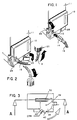
- a filler block 10 forming part of an anaesthetic vaporiser 11 includes an opening 12 which receives an outlet termination 14 forming part of a bottle adaptor 16.
- the bottle adaptor 16 includes a tube 18 connecting the outlet termination 14 to a cap connection 20.
- the cap connection 20 is screwed on to the threaded neck of a bottle (not shown) containing liquid anaesthetic agent and slots in a cap forming part of the cap connection co-operate with lugs on a coded collar (not shown) arranged around the neck of the bottle.
- the outlet termination 14 is keyed, for example, a slot is positioned and/or dimensioned to mate with a locating tongue or peg on the filler block 10 so that only an outlet termination 14 of the correct shape can enter the opening 12.
- the outlet termination 14 is located in the opening 12 and a clamp lever 26 is tightened by rotation from the position shown in Figure 1 to the position shown in Figure 2.
- the bottle is lifted as illustrated in Figure 2 and a valve lever 28 is opened allowing liquid anaesthetic agent to enter the vaporiser via the filler block 10 from the bottle.
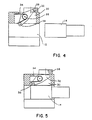
- a cam restrictor 32 mounted for rotation around a horizontal axis 28 in a recess 30 formed in the filler block 10 adjacent the opening 12 is a cam restrictor 32.
- a spring 34 reacts against a lug 36 formed on the restrictor 32 so that a portion including the lug 36 at one end of the restrictor 32 extends into the opening 12. At its opposite end a portion extends into the opening 12. At its opposite end a portion of the restrictor 32 extends into the path of a cam 38 mounted for rotary movement about a vertical axis 39.
- the cam 38 is formed with peripheral teeth 40 and a peg 42.
- the peg 42 is located in a slot 44 formed in a plate 46 attached for movement with valve lever 28.
- the slot 44 has two portions namely a portion 44A and a portion 44B approximately at right angles to the portion 44A.
- the valve lever 28 and hence the plate 46 rotate about a vertical axis 48 and the slot portion 44A throughout its length is radially equidistant from the axis 48.
- a clamp lever actuator 50 mounted on a horizontal axis 52.
- the clamp lever actuator 50 is arranged to move with the clamp lever 26.
- the clamp lever actuator 50 includes an arm 54 which when the clamp lever 26 and hence the clamp lever actuator 50 are turned about the axis 52, engages the teeth 40 to rotate the cam 38 about the axis 39.
- the restrictor 32 Prior to insertion of the outlet termination 14 into the opening 12, the restrictor 32 assumes the position illustrated in Figure 4 with its lower (as shown) end protruding into the opening 12 and its upper (as shown) end extending into the path of the cam 38 thereby preventing rotary movement of said cam 38.
- the outlet termination 14 is inserted into the opening 12 which causes the restrictor 32 to move clockwise (as shown) against the bias of spring 34 into the position shown in Figure 5. As shown in Figure 5, this causes the upper portion of the restrictor to move clear of the cam 38. Once the restrictor 32 is clear of the cam 38 it is then possible to rotate the clamp lever 26 and hence the clamp lever actuator 50 from the position shown in Figure 1 to the position shown in Figure 2 which will cause the arm 54 to engage the teeth 40 on the cam 38 thereby moving the cam anti-clockwise around the axis 39. This has the effect of moving the peg 42 from the slot portion 44B into the slot portion 44A. It is only then possible that the valve lever 28 can be moved to the open position shown in Figures 6 and 7.
- valve lever 28 When it is desired to close the valve lever 28 and remove the outlet termination 14 from the opening 12 then the valve lever is returned to the position shown in Figures 8 and 9 which will cause the peg 42 to move to the junction between the slot portions 44A and 44B.
- the clamp lever 26 and clamp lever actuator 50 can then be moved anti-clockwise causing the arm 54 to engage the teeth 40 and move the cam clockwise and hence the peg 42 along the slot portion 44B to the position shown in Figures 8 and 9.
- the outlet termination 14 is then removed from the opening 12 in the filler block 10 and the anaesthetic vaporiser is then ready for use.
- the interlock mechanism prevents the removal of the outlet termination 14 before the valve lever 28 is closed thereby safeguarding against spillage of anaesthetic agent.
- the fluid delivery system together with the interlock mechanism could be applied to the filling of other types of vessels in which it is important that a valve providing access to the interior of the vessel cannot be opened until the delivery means is clamped in position ready to deliver fluid.
Landscapes
- Health & Medical Sciences (AREA)
- Anesthesiology (AREA)
- Emergency Medicine (AREA)
- Pulmonology (AREA)
- Engineering & Computer Science (AREA)
- Biomedical Technology (AREA)
- Heart & Thoracic Surgery (AREA)
- Hematology (AREA)
- Life Sciences & Earth Sciences (AREA)
- Animal Behavior & Ethology (AREA)
- General Health & Medical Sciences (AREA)
- Public Health (AREA)
- Veterinary Medicine (AREA)
- Filling Of Jars Or Cans And Processes For Cleaning And Sealing Jars (AREA)
- Mechanically-Actuated Valves (AREA)
Applications Claiming Priority (2)
| Application Number | Priority Date | Filing Date | Title |
|---|---|---|---|
| GB909009730A GB9009730D0 (en) | 1990-05-01 | 1990-05-01 | Device for filling anaesthetic vaporisers |
| GB9009730 | 1990-05-01 |
Publications (1)
| Publication Number | Publication Date |
|---|---|
| EP0455433A1 true EP0455433A1 (de) | 1991-11-06 |
Family
ID=10675258
Family Applications (1)
| Application Number | Title | Priority Date | Filing Date |
|---|---|---|---|
| EP91303803A Withdrawn EP0455433A1 (de) | 1990-05-01 | 1991-04-26 | Flüssigkeitsabgabesystem |
Country Status (3)
| Country | Link |
|---|---|
| EP (1) | EP0455433A1 (de) |
| CA (1) | CA2041184A1 (de) |
| GB (1) | GB9009730D0 (de) |
Cited By (6)
| Publication number | Priority date | Publication date | Assignee | Title |
|---|---|---|---|---|
| EP0578513A1 (de) * | 1992-07-10 | 1994-01-12 | Instrumentarium Corporation | Verbindungsvorrichtung |
| GB2281740A (en) * | 1993-09-13 | 1995-03-15 | Draegerwerk Ag | Safety filling device for anaesthetic vaporizer |
| WO1995018644A1 (en) * | 1994-01-07 | 1995-07-13 | Abbott Laboratories | Anesthetic transfer system |
| US5585045A (en) * | 1994-10-18 | 1996-12-17 | Instrumentarium Oy | Arrangement for filling an anaesthetic vaporiser |
| DE19613827C1 (de) * | 1996-04-06 | 1997-04-17 | Draegerwerk Ag | Sicherheitsfüllvorrichtung zum Einfüllen einer Narkoseflüssigkeit in ein Vorratsgefäß einer Narkosemitteldosiervorrichtung |
| EP0781568A2 (de) | 1995-12-28 | 1997-07-02 | Instrumentarium Oy | Verfahren und Vorrichtung zum Füllen eines Narkosemittelverdunsters |
Families Citing this family (2)
| Publication number | Priority date | Publication date | Assignee | Title |
|---|---|---|---|---|
| US5478506A (en) * | 1994-11-17 | 1995-12-26 | Southmedic Inc. | Key-fill vaporizer adaptor with overfill protection |
| CN101376040B (zh) | 2007-08-31 | 2012-06-27 | 深圳迈瑞生物医疗电子股份有限公司 | 二氧化碳吸收罐安装装置 |
Citations (4)
| Publication number | Priority date | Publication date | Assignee | Title |
|---|---|---|---|---|
| EP0038768A1 (de) * | 1980-04-23 | 1981-10-28 | S.A. DES ETABLISSEMENTS STAUBLI (France) | Verriegelung für Rohrverbindung mit Ventil |
| US4434790A (en) * | 1981-08-18 | 1984-03-06 | Puritan-Bennett Corporation | Vaporizer subsystem for an anesthesia machine |
| FR2570609A1 (fr) * | 1984-09-22 | 1986-03-28 | Draegerwerk Ag | Dispositif recepteur pour le remplissage d'un liquide anesthesique |
| EP0295671A2 (de) * | 1987-06-19 | 1988-12-21 | Drägerwerk Aktiengesellschaft | Sicherheitsfüllvorrichtung zum Befüllen und Entleeren eines Narkosemittelverdunsters |
-
1990
- 1990-05-01 GB GB909009730A patent/GB9009730D0/en active Pending
-
1991
- 1991-04-25 CA CA 2041184 patent/CA2041184A1/en not_active Abandoned
- 1991-04-26 EP EP91303803A patent/EP0455433A1/de not_active Withdrawn
Patent Citations (4)
| Publication number | Priority date | Publication date | Assignee | Title |
|---|---|---|---|---|
| EP0038768A1 (de) * | 1980-04-23 | 1981-10-28 | S.A. DES ETABLISSEMENTS STAUBLI (France) | Verriegelung für Rohrverbindung mit Ventil |
| US4434790A (en) * | 1981-08-18 | 1984-03-06 | Puritan-Bennett Corporation | Vaporizer subsystem for an anesthesia machine |
| FR2570609A1 (fr) * | 1984-09-22 | 1986-03-28 | Draegerwerk Ag | Dispositif recepteur pour le remplissage d'un liquide anesthesique |
| EP0295671A2 (de) * | 1987-06-19 | 1988-12-21 | Drägerwerk Aktiengesellschaft | Sicherheitsfüllvorrichtung zum Befüllen und Entleeren eines Narkosemittelverdunsters |
Cited By (12)
| Publication number | Priority date | Publication date | Assignee | Title |
|---|---|---|---|---|
| EP0578513A1 (de) * | 1992-07-10 | 1994-01-12 | Instrumentarium Corporation | Verbindungsvorrichtung |
| US5398737A (en) * | 1992-07-10 | 1995-03-21 | Instrumentarium Corporation | Connecting mechanism |
| GB2281740A (en) * | 1993-09-13 | 1995-03-15 | Draegerwerk Ag | Safety filling device for anaesthetic vaporizer |
| DE4331035A1 (de) * | 1993-09-13 | 1995-03-16 | Draegerwerk Ag | Sicherheitsfüllvorrichtung mit einem Verschlußelement |
| GB2281740B (en) * | 1993-09-13 | 1996-11-20 | Draegerwerk Ag | Safety filling device with a closure device |
| WO1995018644A1 (en) * | 1994-01-07 | 1995-07-13 | Abbott Laboratories | Anesthetic transfer system |
| US5810001A (en) * | 1994-01-07 | 1998-09-22 | Abbott Laboratories | Anesthetic transfer system |
| US5585045A (en) * | 1994-10-18 | 1996-12-17 | Instrumentarium Oy | Arrangement for filling an anaesthetic vaporiser |
| EP0710489A3 (de) * | 1994-10-18 | 1997-04-16 | Instrumentarium Oy | Anordnung zum Auffüllen eines Anästhesie-Verdampfers |
| EP0781568A2 (de) | 1995-12-28 | 1997-07-02 | Instrumentarium Oy | Verfahren und Vorrichtung zum Füllen eines Narkosemittelverdunsters |
| US5819814A (en) * | 1995-12-28 | 1998-10-13 | Instrumentarium Oy | Method and assembly for filling an anesthetic evaporator |
| DE19613827C1 (de) * | 1996-04-06 | 1997-04-17 | Draegerwerk Ag | Sicherheitsfüllvorrichtung zum Einfüllen einer Narkoseflüssigkeit in ein Vorratsgefäß einer Narkosemitteldosiervorrichtung |
Also Published As
| Publication number | Publication date |
|---|---|
| GB9009730D0 (en) | 1990-06-20 |
| CA2041184A1 (en) | 1991-11-02 |
Similar Documents
| Publication | Publication Date | Title |
|---|---|---|
| EP0568565B1 (de) | Flüssigkeitsabgabesystem | |
| US5687777A (en) | Anesthetic agent filler valve | |
| EP0455433A1 (de) | Flüssigkeitsabgabesystem | |
| US8528550B2 (en) | Outlet device for controlling anesthetic flow in vaporizer | |
| EP0264115B1 (de) | Einwegverpackung für Sirup mit integriertem Ventil | |
| US6676172B2 (en) | Anesthetic gas vaporizer with a connection arrangement for a collar-equipped gas bottle | |
| US5682874A (en) | System for connecting an inhalation agent container to a vaporizer | |
| AU602504B2 (en) | Drug handling apparatus and method | |
| EP0662851B1 (de) | ABGABESYSTEM FüR MEDIKAMENTE | |
| EP1512638B1 (de) | Flüssigkeitsabgabesystem mit geschlossenem Kreislauf | |
| US8474451B2 (en) | Device with outlet for controlling anesthetic flow | |
| US5915427A (en) | Anesthetic vaporizer draining system | |
| KR101342985B1 (ko) | 조제, 특히 방사성 동위 원소 발생기에서 이용되기 위한 향상된 콘테이너 | |
| US5170823A (en) | Device for filling an anaesthetic vaporizer | |
| US6745800B1 (en) | Arrangement for preventing overfill of anesthetic liquid | |
| AU2010222937C1 (en) | Valve with biasing member | |
| US3565133A (en) | Volatile anesthetic vaporizing apparatus | |
| US6321948B1 (en) | Tap and valve assembly | |
| US4307718A (en) | Vaporizer interlock | |
| WO2010077585A2 (en) | Smooth-sided outlet device for controlling anesthetic flow in vaporizer with plunger | |
| US7886780B2 (en) | Method and apparatus for preventing drug reservoir overfill | |
| EP0781570B1 (de) | System zum Leeren und Füllen eines Narkosemittelverdunsters | |
| EP0242979A2 (de) | Fülleinrichtung für ein Narkose-Verdampfungsgerät | |
| JP4723809B2 (ja) | ディスペンサを容器に取り付けるための非取外し式の装置 | |
| EP0578513B1 (de) | Verbindungsvorrichtung |
Legal Events
| Date | Code | Title | Description |
|---|---|---|---|
| PUAI | Public reference made under article 153(3) epc to a published international application that has entered the european phase |
Free format text: ORIGINAL CODE: 0009012 |
|
| AK | Designated contracting states |
Kind code of ref document: A1 Designated state(s): DE ES FR GB IT NL |
|
| STAA | Information on the status of an ep patent application or granted ep patent |
Free format text: STATUS: THE APPLICATION IS DEEMED TO BE WITHDRAWN |
|
| 18D | Application deemed to be withdrawn |
Effective date: 19920507 |