EP0455443A2 - Verfahren zur Detektion von Lageabweichungen - Google Patents
Verfahren zur Detektion von Lageabweichungen Download PDFInfo
- Publication number
- EP0455443A2 EP0455443A2 EP91303846A EP91303846A EP0455443A2 EP 0455443 A2 EP0455443 A2 EP 0455443A2 EP 91303846 A EP91303846 A EP 91303846A EP 91303846 A EP91303846 A EP 91303846A EP 0455443 A2 EP0455443 A2 EP 0455443A2
- Authority
- EP
- European Patent Office
- Prior art keywords
- order
- light
- diffracted
- grating mark
- grating
- Prior art date
- Legal status (The legal status is an assumption and is not a legal conclusion. Google has not performed a legal analysis and makes no representation as to the accuracy of the status listed.)
- Granted
Links
Images


Classifications
-
- G—PHYSICS
- G03—PHOTOGRAPHY; CINEMATOGRAPHY; ANALOGOUS TECHNIQUES USING WAVES OTHER THAN OPTICAL WAVES; ELECTROGRAPHY; HOLOGRAPHY
- G03F—PHOTOMECHANICAL PRODUCTION OF TEXTURED OR PATTERNED SURFACES, e.g. FOR PRINTING, FOR PROCESSING OF SEMICONDUCTOR DEVICES; MATERIALS THEREFOR; ORIGINALS THEREFOR; APPARATUS SPECIALLY ADAPTED THEREFOR
- G03F9/00—Registration or positioning of originals, masks, frames, photographic sheets or textured or patterned surfaces, e.g. automatically
- G03F9/70—Registration or positioning of originals, masks, frames, photographic sheets or textured or patterned surfaces, e.g. automatically for microlithography
- G03F9/7073—Alignment marks and their environment
- G03F9/7076—Mark details, e.g. phase grating mark, temporary mark
Definitions
- This invention relates to a positional deviation detecting method usable in a semiconductor device manufacturing exposure apparatus for photolithographic transfer of a fine pattern such as a semiconductor integrated circuit, for detecting positional deviation orthe like between a mask (reticle) and a wafer at high precision.
- the relative alignment of a mask and a wafer is one importantfactor in respect to ensuring improved performance.
- alignment systems employed in recent exposure apparatuses submicron alignment accuracies or more strict accuracies are required in consideration of the demand for higher degree of integration of semiconductor devices.
- alignment marks In many types of alignment systems, features called "alignment marks" are provided on a mask and a wafer and, by utilizing positional information obtainable from these marks, the mask and wafer are aligned.
- the manner of executing the alignment as an example there is a method wherein the amount of relative deviation of these alignment patterns is detected on the basis of image processing.
- Another method is proposed in U.S. Patent Nos. 4,037,969 and 4,513,858 and Japanese Laid-Open Patent Application, Laid-Open No. Sho 56-157033, wherein so-called zone plates are used as alignment marks upon which light is projected and wherein the positions of light spots formed on a predetermined plane by lights from the illuminated zone plates are detected.
- an alignment method utilizing a zone plate is relatively insensitive to any defect of an alignment mark and therefore assures relatively high alignment accuracies, as compared with an alignment method simply using a traditional alignment mark.
- Figure 1 is a schematic view of a known type alignment system utilizing zone plates.
- this type of position detecting system is disclosed in European Patent Application 0,333,326A2, filed under the name of the assignee of the subject application.
- Mask 1 is adhered to a membrane 47 which is supported by a main frame 45 of an aligner through a mask chuck 46.
- Mask-to-wafer alignment head 44 is disposed above the main frame 45.
- a mask alignment mark 3M and a wafer alignment mark 4W are formed on the mask 1 and the wafer 2, respectively.
- the alignment mark 3M is provided by a transmission type zone plate, and positive first order diffraction light thereof is influenced by a convex lens function, converging at a point Q.
- the wafer alignment mark 4W is provided by a reflection type zone plate, and it has a convex mirror function (diverging function) for imaging the light, convergent at point Q, upon a detection surface 39.
- the signal light having been influenced by negative first order reflective diffraction of the wafer alignment mark 4W is not influenced by any lens function as the same passes through the mask M, and the light transmitted therethrough as zero-th order diffraction light is collected on detection surface 39 of a detector 38.
- zero-th order diffraction means simple transmission or specular reflection.
- the light influenced by m-th order diffraction by the mask 1 and subsequently influenced by n-th order diffraction by the wafer 2 and again influenced by f-th order diffraction by the mask will be referred to as "(m, n, f)-th order light”. Accordingly, the above-described light can be referred to as "(1, -1, 0)-th order light”. This light provides the signal light.
- any positional deviation between the mask 1 and the wafer 2 is detected on the basis of the position of incidence of the signal light upon the detection surface 39.
- the proportional constant thereof corresponds to the magnification of deviation detection. More specifically, if under such arrangement the wafer 2 laterally shifts by ⁇ w relative to the mask 1, the position of incidence of the light on the detection surface 39 displaces by ⁇ w which can be expressed as follows:
- This quantity "bw/aw - 1" represents the deviation detecting magnification.
- aw denotes the distance to the wafer from the point Q of convergence of the signal light emanating from the mask
- bw denotes the distance from the wafer to the detection surface 39.
- (0, -1, 1)-th order light which is different in diffraction order is nearly focused on the detection surface 39.
- the (0, -1, 1)-th order light is such light as: having been inputted to the mask alignment mark 3M; having been transmitted therethrough at zero-th order; having been reflectively diffracted at negative first order by the wafer alignment mark 4W and influenced by the concave power (diversion) function; further having been transmissively diffracted at positive first order by the mask alignment mark 3M and influenced by the convex power (convergence) function; and nearly focused on the detection surface 39.
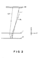
- Figure 2 schematically shows propagation of an input light AL, a (1, -1,0)-th order light L1 and a (0.1,1)-th order light L2 as well as an optical arrangement.
- the ratio of intensity of these lights changes with such change. This results in a change in the overall deviation detecting magnification of the (1, -1, 0)-th order light and the (0, -1, 1)-th order light and, therefore, it causes an error in the deviation detection.
- a method of detecting a relative positional deviation of a first object having a first grating mark with an optical power and a second object having a second grating mark with an optical power wherein a projected radiation beam is diffracted by the first and second grating marks in sequence and, on the basis of a position of convergence on a light receiving surface of plural diffraction beams produced by the diffraction through the first and second grating marks and including a signal beam having been diffracted at a predetermined order by each of the first and second grating marks, the relative positional deviation is determined, characterized in that: a detection zone is defined on the light receiving surface; that the signal beam is caused to be converged upon the detection zone; and that a predetermined diffraction beam of the plural diffraction beams which, for a relative positional deviation of the first and second objects, shows displacement different from that of the signal beam is substantially prevented from being converged upon
- a position detecting system is featurized in that: A first alignment mark having a light diffracting function is provided on a first object while a second alignment mark having a light diffracting function is provided on a second object, wherein these alignment marks are so formed that, of light from light projecting means, when m, n and are integers, the position of convergence on a predetermined plane of a first light having been diffracted at m-th order by the first alignment mark, having been diffracted at n-th order by the second alignment mark and having been diffracted at f-th order again by the first alignment mark, is displaceable at a predetermined magnification in response to a relative positional deviation of the first and second objects.
- the relative positional deviation of the first and second objects is determined by detecting the position of convergence of the first light on the predetermined plane, wherein, where m', n' and E'are integers satisfying m'xm, n';t:n or l' ⁇ l, the position of convergence on the predetermined plane of a second light having been diffracted at m'-th order by the first alignment mark, having been diffracted at n'-th order by the second alignment mark and having been diffracted at f'-th order again by the first alignment mark, is spaced from the position of convergence of the first light by a distance at least twice larger than the spot diameter of the first or second light (preferably the larger one of them). This assures that the second light is substantially prevented from being converged upon a predetermined detection zone of the predetermined plane on which the first light is to be detected.
- first and second (signal producing) alignment marks A1 and A2 each having a function of a physical optic element
- first and second (signal producing) alignment marks B1 and B2 similarly each having a function of a physical optic element, are formed.
- Light is inputted to the alignment mark A1, and diffraction light caused thereby is inputted to the alignment mark B1.
- Diffraction lightfrom the alignment mark B1 is incident on a predetermined plane, and the gravity center of the incident light on that plane is detected by a first detecting means, provided on that plane, as the position of incidence of the first signal light
- the term "gravity center of light” means such a point that, when on a light receiving surface a position vector of each point on the surface is multiplied by the light intensity of that point and the thus obtained products are integrated over the entire surface, the integrated level has a "zero vector".
- the position of a peak point of the light intensity may be detected.
- the alignment marks A1, A2, B1 and B2 are so set that the gravity center position of the light incident on the first detecting means and the gravity center position of the light incident on the second detecting means, shift in opposite directions in response to a positional deviation between the objects A and B.
- Figure 3 is a schematic view for explaining the principle of a first aspect of the present invention as well as structural features of it.
- Figure 4 is a perspective view of a major part of a first embodiment of the present invention, based on the Figure 3 structure.
- denoted at 1 is a first object (object surface A) which is a mask, for example, and denoted at 2 is a second object (object surface B) which is a wafer, for example.
- object surface A which is a mask
- object surface B which is a wafer
- the illustrated is an example wherein a relative positional deviation of the first and second objects it to be detected.
- the first object is illustrated in duplication.
- Denoted at 5 and 3 are alignment marks which are provided on the first and second objects 1 and 2, respectively, for obtaining a first signal light.
- denoted at 6 and 4 are alignment marks provided on the first and second objects 1 and 2, respectively, for obtaining a second signal light.
- the paths are illustrated with the alignment marks 3 and 4 being replaced by equivalent transmission type alignment marks.
- Each of the alignment marks 3 - 6 serves as a physical optic element such as, for example, a grating lens having an optical power (such as a one-dimensional or two-dimensional lens or mirror function) or a diffraction grating having no lens function.
- Denoted at 9 is a wafer scribe line and denoted at 10 is a mask scribe line.
- Each alignment mark is formed on the corresponding scribe line.
- Reference numerals 7 and 8 denote the first and second (alignment) signal lights, while reference numerals 7' and 8' denote (unwanted) diffraction lights of predetermined orders related to the first and second signal lights 7 and 8.
- the first signal light 7 is provided by a (1, -1, 0)-th order light
- the second signal light 8 is provided by a (-1, 1, 0)-th order light
- the light 7' is provided by a (0, -1, 1)-th order light
- the light 8' is provided by a (0,1, -1)-th order light.
- first and second detecting means for detecting the first and second signal lights 7 and 8, respectively.
- Each of the first and second detecting means comprises a one-dimensional (linear) CCD sensor, for example, having its sensing elements arrayed in the X-axis direction.
- the optical distance from the second object 2 to the first detecting means 11 or the second detecting means 12 is denoted by L.
- L denotes the distance between the first and second objects 1 and 2
- f a1 and f a2 denote the focal lengths of the alignment marks 5 and 6
- ⁇ denotes the relative positional deviation of the first and second objects 1 and 2
- S 1 and S Z denote displacements of the gravity center positions of the first and second signal lights on the first and second detecting means, respectively, at that time, from the positions as assumed under correct alignment
- the alignment light inputted to the object 1 is a plane wave. The signs are such as illustrated.
- Each of the displacements S 1 and S 2 can be determined geometrically as a point of intersection between (i) the light receiving surface of the first (or second) detecting means 11 or 12 and (ii) the straight line that connects the focal point F 1 (F 2 ) of the alignment mark 5 (6) and the optical axis center of the alignment mark 3 (4). Therefore, the opposability in direction of the displacements S 1 and S 2 of the gravity centers of these lights, responsive to a relative positional deviation of the first and second objects 1 and 2, is attainable by applying an inversive relationship to the signs of optical imaging magnifications of the alignment marks 3 and 4.
- examples that can be used as a light source are: a light source such as a semiconductor laser, a He-Ne laser, an Ar laser or the like that can emit a coherent light; and a light source such as a light emitting diode or the like that can emit an incoherent light.
- the (1, -1, 0)-th order light which is the lights 7 as well as the (-1, 1, 0)-th order light which is the light 8, are those lights: which are incident upon the alignment marks 5 and 6, respectively, on the mask 1 surface each at a predetermined angle; which are then transmissively diffracted by these marks and then reflectively diffracted by the alignment marks 3 and 4 on the wafer 2 surface, respect- i vely; and which are then incident on the detecting means 11 and 12, respectively.
- the (0, -1, 1)-th order light which is the light 7' as well as the (0, 1, -1)-th order light which is the light 8' are those lights: which are transmitted atzero-th order by the alignment marks 5 and 6 on the mask 1; which are then reflectively diffracted by the alignment marks 3 and 4 on the wafer 2 surface, respectively; and which are then transmis- s i vely diffracted by the alignment marks 5 and 6 on the mask 1 surface and incident on the detecting means 11 and 12.
- the gravity center positions of the first and second alignment lights, respectively, incident on the respective detecting means are detected and, by using output signals from the detecting means 11 and 12, any positional deviation of the mask 1 and the wafer 2 can be detected. At this time, the output signals corresponding to the lights 7' and 8 are not used for the detection.
- the alignment marks 3 - 6 are provided by Fresnel zone plates (or grating lenses) having different focal lengths. Practical size of each mark is 50 - 300 microns in the lengthwise direction (X-axis direction) of the scribe line 9 or 10 and 20 - 100 microns in the widthwise direction (Y-axis direction) of the scribe line.
- all the lights 7, 7', 8 and 8' are incident on the mask 1 at an angle of incidence of about 17.5 deg., with the projection component upon the mask 1 surface being perpendicular to the scribe line direction (X-axis direction).
- the mask 1 and the wafer 2 are spaced from each other by a gap of 30 microns.
- the (1, -1, 0)-th order light 7 has been transmissively diffracted at first order by the alignment mark 5 and influenced by the convex lens function and, then, having been reflectively diffracted at negative first order by and influenced by the concave lens function of the alignment mark 3 on the wafer 2 surface and, thereafter, it is focused at a point on the first detecting means 11.
- the (0, -1,1 1)-th order light which is the light 7' has been transmitted (diffracted) atzero-th order through the mask 1 surface and then reflectively diffracted at first order by the alignment mark 3 on the wafer 2surface and influenced by the convex lens function, and thereafter, transmissively diffracted at first order by the alignment mark 5 on the mask 1 surface and influenced by the concave lens function, and finally it impinges on the detecting means 11 surface.
- displacement of the position of incidence of this light 7 corresponds to the quantity of positional deviation between the alignment marks 5 and 3 in the X-axis direction, namely, the quantity of misalignment of the axes of them.
- the light is inputted, bearing magnified quantity of positional deviation. As a result of this, the shift of the gravity center position of the inputted light can be detected by the detecting means 11.
- the present embodiment is so set that, when the mask 1 and the wafer 2 have no relative positional deviation (i.e., when the alignment marks 5 and 3 on the mask 1 and the wafer 2 just provide a coaxial system), the chief ray of the light 7 emitted from the wafer 2 has an angle of emission of 13 deg., and the projection of the emitted light upon the wafer 2 surface extends perpendicularly to the widthwise direction (Y-axis direction) of the scribe line, and the light 7 is focused on the detecting means 11 surface which is disposed at a predetermined position, for example, at a height of 18.657 mm from the wafer 2 surface.
- the light 8 has been transmissively diffracted by the alignment mark 6 and then reflectively diffracted by the alignment mark 4 on the wafer 2 surface.
- the mark 4 serves so that the position of the spot of the light 8 formed thereby is displaced in a direction different from that of the spot of the light 7.
- the chief ray of the emitted light 8 from the wafer 2 has an angle of emission of 7 degrees, with the projection upon the wafer 2 surface being perpendicular to the widthwise direction of the scribe line, and the light is focused upon the detecting means 12 surface which is provided at a height higher than that of the first detecting means.
- the X-axis component of the interval i.e., the spacing along the X-axis direction, between the gravity center position of the light 7 on the detecting means 11 surface and the gravity center position of the light 8 on the detecting means 12 surface.
- the spacing between the mask and the wafer is g and the spacing between the wafer and the light receiving surface of the detector is L
- the displacements S 1 and S 2 of the gravity centers of the lights are expressed quantitatively, such as follows:
- the quantity of change (AD) in the spacing of the lights 7 and 8 on the detecting means 11 and 12 in the X direction can be given by the following equation:
- the positional deviation can be detected in the following manner.
- the spacing D between the gravity center positions as assumed when the mask and the wafer have no relative positional deviation in the X direction can be determined beforehand by calculation or by trial printings. Then, during actual detection of the relative positional deviation of the mask and the wafer in the X direction, a deviation AD of the spacing between the gravity center positions of the lights 7 and 8, with reference to the quantity D, can be detected and, from the detected deviation AD, the relative positional deviation of the mask and the wafer in the X direction can be determined by calculation.
- the center position (optical axis position) of the alignment mark 3 of the second object as there is no relative positional deviation is denoted by (x w1 , y w1 , -g) and also that the alignment mark 3 is so designed as to form, at a position (x s1 , y s1 , z s1 ), an image of a point light source (point image) which is at a position (x M1 , y M1, -f i ) if there is no positional deviation.
- the center position (optical axis position) of the alignment mark 6 of the first object is denoted by (xmo2, y M02, 0) and, like the alignment mark 5, its imaging point position is denoted by (x M2 , Y M2 , -f 3 ).
- the center position (optical axis position) of the alignment mark 4 as there is no positional deviation is denoted by (x w2 , y w2 , -g) and that the mark 4 is so designed as to form, at a position (x s2 , YS2 , z s2 ), an image of a point light source (point image) which is at a position (x M2 , y M2 , -f 3 ) as there is no positional deviation.
- the distance from the mask surface to the detecting means surface is denoted by L'.
- x MI and x Wi are the quantities that are determined by the angles of deflection, with respect to the chief ray of input light, of the alignment marks of the first and second objects as well as the focal lengths of these marks, respectively, and they are expressed as follows:
- the center of the alignment mark of the first object is taken as an origin; the X axis is laid on the alignment mark surface along direction with respect to which the positional deviation is to be detected; the Y axis is laid along a direction perpendicular to the X axis; and the Z axis is laid along a direction of a normal to the alignment mark surface.
- the detecting means has a light receiving zone with its center denoted by (x s , y s , z s ), and the light receiving zone has a rectangular shape of a size d 1 in the X direction and d 2 in the direction perpendicular thereto.
- the quantities S 21 and S 22 satisfy the following relations: then, it is assured that the light (0, -1, 1)-th order light which is the light 7 or the (0, 1, -1)-th order light which is the light 8 is prevented from impinging on the light receiving zone, in the range ⁇ 1 ⁇ ⁇ ⁇ ⁇ 2 .
- the quantities 1 and s 2 are so selected to have the values as described, and by this thp inconveniences describe hereinbefore are avoided.
- the quantities x M1 , XM2 , x W1 and x W2 are set so as to satisfy the following relations:
- S 21 and S 22 are: If - 3.0 ⁇ ⁇ ⁇ 3.0, then:
- the present embodiment is arranged so that the (0, -1,1 )-th order light or the (0,1, -1)-th order light is prevented from impinging on the light detecting zone of each detecting means 11 or 12.
- ⁇ , x W1 , x M1 and the like it is possible to relatively separate the gravity center positions on the detecting means surface of the (1, -1, 0)-th order light and the (0, -1, 1)-th order light, or the (-1, 1, 0)-th order light and the (0, 1, -1)-th order light, by a distance within the deviation detectable range but larger than a predetermined length.
- the relative distance l 1 of the gravity centers of the (1, -1, 0)-th order light (light 7) and the (0, -1, 1)-th order light (light 7'), upon the detecting means surface is: wherein
- the parameters f 1 , f 2 , L, L', x M01 , x M1 and 9 may be so set that, within the measurement range ⁇ 1 ⁇ ⁇ ⁇ ⁇ 2 , the distance f always satisfies the following relation: wherein l min is the allowable minimum quantity for the relative gravity center spacing of the two lights 7 and 7' as they come close to each other on the detecting means surface.
- ⁇ 1 and a 2 denote the 1/e 2 light systems (spot diameters) of these lights on the detecting means surface
- ⁇ 1 and a 2 are determined by L and the mark size in the X direction, and the condition for the separation of the two lights is given by:
- y is a constant satisfying y > 1.0 and, generally, ⁇ ⁇ 2.0 is preferable. Namely, it is preferable that the lights are separated by a distance at least four times larger than the spot diameter, where ⁇ 1 ⁇ ⁇ 2 . Similar setting should be made with regard to the second signal light, too.
- a practical example of parameter setting may be such that: Where only the gravity centers of the (1, -1, 0)-th order light and the (-1, 1, 0)-th order light of the first and second signal lights are to be detected and processed.
- the relative gravity center spacing l of the two lights to be considered on the detecting means surface in relation to the positional deviation ⁇ is given by:
- the parameters are set so as to satisfy equations (9-5) to (9-12).
- the parameters are set so as to satisfy the conditions, such as given by equations (9-13) to (9-15), below, which are to be satisfied by the relative gravity center spacing l 2 on the detecting means surface of the (-1,1,0)-th order light 8 and the (0,1, -1)-th order light 8':
- the parameters f i - f4, L, L', x M01 , x M1 , x Mo2 , x M2 and 8 are set so that total eight equations (9-5) to (9-8) and (9-12) to (9-15) are satisfied. Since there are eight conditional equations (including inequality) for unknown quantities of a number eleven (11), the solutions are not determined definitely, and it is necessary to adopt such a process in which f 1 , f 3 and L', for example, are first given and then numerical solutions are determined.
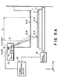
- Figure 5A shows a proximity type semiconductor device manufacturing exposure apparatus (X-ray exposure apparatus) into which the first embodiment of the present invention shown in Figure 4 is incorporated.
- the apparatus is equipped with a light source 13, a collimator lens system (or a beam diameter changing lens) 14, a projected light deflecting mirror 15, a pickup casing (alignment head casing) 16, a wafer stage 17, a positional deviation signal processing means 18, a wafer stage drive control means 19, and the like.
- Character E denotes the width of the exposure light (X-ray flux) in the X direction.
- any relative positional deviation of the mask (first object) 1 and the wafer (second object) 2 is detected in a similar manner as having been described with reference to the first embodiment
- a first example is that: Signals representing displacements ⁇ of gravity centers of the lights upon the detection surfaces 11 a and 12 b of the detecting means 11 and 12, corresponding to the positional deviation ⁇ between two objects, are detected and, in the signal processing means 18, the positional deviation ⁇ between these objects is detected on the basis of the signals representing the displacements of the gravity centers. Then, the stage drive control 19 operates to move the wafer stage 17 by an amount corresponding to the detected positional deviation ⁇ .
- a second example is that: From the signals outputted by the detecting means 11 and 12, the signal processing means 18 detects such a direction that cancels the positional deviation ⁇ .
- the stage drive control 19 operates to move the wafer stage 17 in that direction, and the above-described operations are repeated until the positional deviation comes into a tolerable range.
- the light source 13 projects light from outside of the path of the exposure light to the alignment marks 5 and 6, and that the detecting means 11 and 12 which are provided outside the exposure light flux receive diffraction lights emanating from the alignment marks 3 and 4 outwardly of the exposure light, for the position detecting purpose.
- equations (1), (2'), (3) and (4') related to the position of incidence of the (1, -1, 0)-th order light, the (-1,1,0)-th order light, the (0, -1, 1)-th order light and the (0, 1, -1)-th order light upon the detecting means surface may be used to determine the location of the detecting means as well as the size thereof, for example, so that the light receiving zone of the detecting means receives the (0, -1, 1)-th order light or the (0, 1, -1)-th order light as the alignment signal light, with the other lights being prevented from being received. Since this modification will have an arrangement basically similar to that of the first embodiment, the explanation of the structure itself will be omitted.
- the angle 9 of incidence of the light upon the alignment mark in the X-Z plane as well as the eccentric parameters X M1 , X M2 , X W1 , X W2 and the like are the same as those of the first embodiment, but the location of the detecting means or the size thereof is different
- the centercoordinate (x s , y s , z s ) of the detecting means is set as follows: so as to assure that only the (0, -1, 1)-th order light or the (0, 1, -1)-th order light is received.
- this embodiment is the same as the first embodiment.
- the size of the light receiving zone of the detecting means is set to be equal to 1.88 mm in the X direction, in consideration of possible quantities of S 21 and S 22 under the condition of the positional deviation detectable range of - 3.0 ⁇ ⁇ ⁇ 3.0 (micron).
- the detecting means can receive only the (0, -1, 1)-th order light or the (0, 1, -1)-th order light and can execute the positional deviation detection without influenced by the (1, -1, 0)-th order light or the (-1, 1, 0)-th order light.
- the structure may be arranged to use, as a positional deviation signal light, such light as transmissively diffracted at m-th order by an alignment mark of a mask, then reflectively diffracted at n-th order by an alignment mark of a wafer and then transmissively diffracted at l-th order again by the mask alignment mark, namely, the (m, n, f)-th order light, wherein m ⁇ 0, nx0 and l ⁇ 0.
- a positional deviation signal light such light as transmissively diffracted at m-th order by an alignment mark of a mask, then reflectively diffracted at n-th order by an alignment mark of a wafer and then transmissively diffracted at l-th order again by the mask alignment mark, namely, the (m, n, f)-th order light, wherein m ⁇ 0, nx0 and l ⁇ 0.
- each alignment mark comprises a one-dimensional grating lens having a cylindrical power
- the X axis is laid in the direction in which the lens power is produced.
- the Y-axis is laid on an axis which passes the center of the alignment mark and intersects at a right angle with the X axis, within the plane of the alignment mark is formed.
- the Z axis is laid on an axis perpendicular to the X and Y axes.
- the angle is defined by: wherein P M and P W are pitches of mask and wafer alignment marks, in the Y-Z plane, having no light converging or diverging function (optical power), and ⁇ denotes the wavelength of the used light.
- the lights to be inputted to the light detection surface at the same time should be, as a first example, those lights which correspond to such a combination of diffraction orders that satisfy: that is, f-th order transmission lights having been transmitted at m-th order by the mask alignment mark and having an "l" satisfying equation (10') again.
- the positional deviation signal light it is a necessary condition for the magnified deviation detection using grating lenses that n ⁇ 0 and at least one of m and l is not equal to 0.
- the focal length of a mask alignment mark corresponding to i-th order diffraction light is fi M and similarly the focal length of a wafer alignment mark 3 corresponding to j-th order diffraction light is fj W , then, from the effective gravity center position of the (m, n, f)-th order light, the positional deviation detecting magnfication ⁇ upon the detecting means for the (m, n, l)-th order light, is given by: where L 1 is given by: and L 2 is the distance from the center of the mask mark to the center of the detection surface.
- L 2 is given by:
- fl M (fmM)
- the optical arrangement including the detecting means and other optical elements is so determined that the (m', n', f')-th order light which satisfies equation (14) below, that is, such light as having approximately the same intensity as the (m, n, f)-th order light upon the detecting means surface, is prevented from reaching the light receiving zone of the detecting means surface.
- Equation (14) represents that, for the distance L 2 to the convergent point position of the (m, n, l)-th order light, the distance L 2 ' to the convergent point position of the (m', n', l')-th order light is of the same level as L 2 and, therefore, that it has approximately the same intensity concentration.
- L2' can be given by:
- the calculation of the position of incidence of light based on equation (11) is effected to such a set of diffraction orders m', n' and f' with respect to which, for particular f1 M , f1 w and g as well as the diffraction orders m, n, f, the ratio of the imaging plane position L 2 of the (m, n, l)-th order light and the imaging plane position L2' of the (m', n', f')-th order light, namely, the difference
- the light projection angle (incidence angle) ⁇ and the focal lengths ofthe alignment marks as well as the locations of the detecting means are determined so as to assure that the spacing between the positions of incidence of these lights on the detecting means surface does satisfy at least equation (9-8) or, alternatively, to assure that the condition for preventing the (m', n', f')-th order light from impinging on the light receiving zone of the detecting means surface, namely, the following condition, is satisfied:
- the position S of incidence of the (m, n, f)-th order light on the detecting means surface in the X direction is:
- Practical process of parameter setting is substantially the same as that of the first embodiment.
- the present invention is not limited to this.
- the invention is applicable also to an arrangement wherein a single detecting means and a single light beam are used, and the relative positional deviation of the mask and the wafer is detected on the basis of proportional relationship between (i) the quantity of deviation of the gravity center position of the diffraction light upon the single detecting means, from a preset reference position thereon, and (ii) the quantity of relative positional deviation of the mask and the wafer.
- two light beams such as in the foregoing embodiments may be inputted to a single detecting means.
- a position detecting system is featurized in that: An alignment mark having a wavefront converting or light diffracting function is provided on a first object while another alignment mark having a wavefront converting or light diffracting function is provided on a second object.
- light from a light projecting means light as influenced by the wavefront converting functions of these alignment marks of the first and second objects is directed to a predetermined plane and, by detecting the position of incidence of that light upon the predetermined plane through a detecting means, the relative positional deviation of the first and second objects is determined.
- the alignment mark of the second object is formed outside a region within which the light diffracted at zero-th order by the alignment mark of the first object is incident on the second object.
- the first object is equipped with two alignment marks A1 and A2 each having a wavefront converting function while the second object is equipped with two alignment marks B1 and B2 each having a wavefront converting function.
- a first light as influenced by the wavefront converting functions of the alignment marks A1 and B1 of the first and second objects as well as a second light as influenced by the wavefront converting functions of the alignment marks A2 and B2 of the first and second objects, are directed to a predetermined plane.
- the relative positional deviation of the first and second objects is determined.
- Two alignment marks of the first object or the second object are formed in a single region in an overlapping or juxtaposed relation, and two alignment marks of the second object are formed outside a region within which the light diffracted at zero-th order by the two alignment marks of the first object is incident on the second object
- the two alignment marks A1 and A2 or the two alignment marks B1 and B2 are provided by a single and common mark.
- first and second signal producing alignment marks A1 and A2 each serving as a physical optic element having a wavefront converting function, are formed on the object surface A, in a separate relation to satisfy a predetermined condition.
- first and second signal producing alignment marks B1 and B2 similarly each serving as a physical optic element, are formed in juxtaposition.
- Light is inputted to the alignment mark A1, and diffraction light caused thereby is inputted to the alignment mark B1.
- Diffraction lightfrom the alignment mark B1 is incident on a predetermined plane, and the gravity center of the incident light on that plane is detected by a first detecting means, as the position of incidence of the first signal light
- the term "gravity center of light” means such a point that, when on a light receiving surface a position vector of each point on the surface is multiplied by the light intensity of that point and the thus obtained products are integrated over the entire surface, the integrated level has a "zero vector".
- the position of a peak point of the light intensity may be detected.
- the alignment marks A1, A2, B1 and B2 are so set that the gravity center position of the light incident on the first detecting means and the gravity center position of the light incident on the second detecting means, shift in opposite directions in response to a positional deviation between the objects A and B.
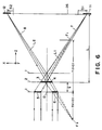
- Figure 6 is a schematic view for explaining the principle of a second aspect of the present invention as well as structural features of it.
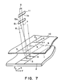
- Figure 7 is a perspective view of a major part of a second embodiment of the present invention, based on the Figure 6 structure.
- denoted at 1 is a first object (object surface A) which is a mask, for example, and denoted at 2 is a second object (object surface B) which is a wafer, for example.
- object surface A which is a mask
- object surface B which is a wafer
- the illustrated is an example wherein a relative positional deviation of the first and second objects it to be detected.
- the first object is illustrated in duplication.
- Denoted at 5 and 3 are alignment marks which are provided on the first and second objects 1 and 2, respectively, for obtaining a first signal light.
- denoted at 6 and 4 are alignment marks provided on the first and second objects 1 and 2, respectively, for obtaining a second signal light.
- the paths are illustrated with the alignment marks 3 and 4 being replaced by equivalent transmission type alignment marks.
- Each of the alignment marks 3 - 6 comprises an optical member with wavefront converting function which serves as a physical optic element such as, for example, a grating lens having an optical power (such as a one-dimensional or two-dimensional lens function) or a diffraction grating having no lens function.
- a physical optic element such as, for example, a grating lens having an optical power (such as a one-dimensional or two-dimensional lens function) or a diffraction grating having no lens function.
- the two alignment marks 5 and 6 provided on the first object 1 are spaced from each other in the alignment direction or the positional deviation detecting direction (X direction), by a predetermined distance.
- the two alignment marks 3 and 4 provided on the second object 2 are juxtaposed with each other.
- the alignment mark setting is such that, when, of light from a light source means (not shown), light inputted to the two alignment marks 5 and 6 of the first object 1 and diffracted at zero-th order by the alignment marks 5 and 6 (simply transmitted) is incident on the second object 2 surface, the two alignment marks 3 and 4 are positioned outside the region in which the light is incident.
- the alignment marks 3 and 4 of the second object are positioned completely outside the region of incidence of the zero-th order diffraction light, and they may partially overlap that region. If, as an example, the area of the overlapped portion is not greater than about 30 % of the area of the alignment mark, the object of the present invention can be accomplished sufficiently.
- This structure is effective to reduce the intensity of unwanted diffraction light, other than the signal light, to a level not greater than one-third of the signal light and, therefore, the effect of the unwanted diffraction light upon the positional deviation detection can be made small.
- Denoted at 9 is a wafer scribe line and denoted at 10 is a mask scribe line. Each alignment mark is formed on the corresponding scribe line.
- Reference numerals 7 and 8 denote the first and second alignment signal tights, while reference numerals 7' and 8' denote (unwanted) diffraction lights of predetermined orders related to the first and second signal lights 7 and 8 and causing a detection error factor.
- the first signal light 7 is provided by a (1, -1, 0)-th order light
- the second signal light 8 is provided by a (-1, 1, 0)-th order light
- the light 7' is provided by a (0, -1, 1)-th order tight
- the light 8' is provided by a (0, 1, -1)-th order light, like the first embodiment.
- first and second detecting means for detecting the first and second signal lights 7 and 8, respectively.
- Each of the first and second detecting means comprises a one-dimensional (linear) CCD sensor, for example, having its sensing elements arrayed in the X-axis direction.
- the optical distance from the second object 2 to the first detecting means 11 or the second detecting means 12 is denoted by L.
- L the optical distance between the first and second objects 1 and 2
- f 1 and f 3 denote the focal lengths of the alignment marks 5 and 6
- ⁇ 0 denotes the relative positional deviation of the first and second objects 1 and 2
- S 1 and S 2 denote displacements of the gravity center positions of the first and second signal lights on the first and second detecting means, respectively, at that time, from the positions as assumed under correct alignment
- the alignment light inputted from an unshown light source to the object 1 is a plane wave. The signs are such as illustrated.
- Each of the displacements S 1 and S 2 can be determined geometrically as a point of intersection between (i) the light receiving surface of the first (or second) detecting means 11 or 12 and (ii) the straight line that connects the focal point F 1 (F2) of the alignment mark 5 (6) and the optical axis center of the alignment mark 3 (4). Therefore, the opposability in direction of the displacements S 1 and S 3 of the gravity centers of these lights, responsive to a relative positional deviation of the first and second objects 1 and 2, is attainable by applying an invers i ve relationship to the signs of optical imaging magnifications of the alignment marks 3 and 4.
- examples that can be used as a lightsource are: a light source such as a semiconductor laser, a He-Ne laser, an Ar laser or the like that can emit a coherent light; and a light source such as a light emitting diode or the like that can emit an incoherent light.
- the (1, -1, 0)-th order light which is the lights 7 as well as the (-1,1, 0)-th order light which is the light 8 are those lights: which are incident upon the alignment marks 5 and 6, respectively, on the mask 1 surface each at a predetermined angle; which are then transmissively diffracted by these marks and then reflectively diffracted by the alignment marks 3 and 4 on the wafer 2 surface, respectively; and which are then incident on the detecting means 11 and 12, respectively.
- the (0, -1, 1)-th order light which is the light 7' as well as the (0,1, -1)-th order light which is the light 8' are those lights: which are transmitted atzero-th order by the alignment marks 5 and 6 on the mask 1; which are then reflectively diffracted by the alignment marks 3 and 4 on the wafer 2 surface, respectively; and which are then transmissively diffracted by the alignment marks 5 and 6 on the mask 1 surface and incident on an area outside the detecting means 11 and 12.
- these lights are incident on the detecting means 11 and 12, they do not adversely affect the detection of the first and second signal lights, and the alignment marks 3 - 6 are so set
- the gravity center positions of the first and second alignment lights 7 and 8, respectively, incident on the respective detecting means 11 and 12 are detected and, by using output signals from the detecting means 11 and 12, any positional deviation of the mask 1 and the wafer 2 can be detected.
- the center position (optical axis position) of the alignment mark 3 of the second object as there is no relative positional deviation is denoted by (x W1 , y W1 , -g) and also that the alignment mark 3 is so designed as to form, at a position (x sl , y si , z S1 ), an image of a point light source (point image) which is at a position (x M1 , y M1 , -f 1 ) if there is no positional deviation.
- the center position (optical axis position) of the alignment mark 6 of the first object is denoted by (X M02 , y M02 , 0) and, like the alignment mark 5, the imaging point position of a parallel light incident on the alignment mark 6 at an angle 8 in the X-Z plane is denoted by (x M2 , y M2 , -f 3 ).
- the center position (optical axis position) of the alignment mark 4 as there is no positional deviation is denoted by (x w2 , y W2 , -g) and that the mark 4 is so designed as to form, at a position (x s2 , y S2 , z S2 ), an image of a point light source (point image) which is at a position ( XM2 , Y M2 , -f 3 ) as there is no positional deviation.
- the distance from the mask surface 26 to the detecting means surface is denoted by L.
- x M1 and x W1 are the quantities that are determined by the angles of deflection, with respect to the chief ray of input light, of the alignment marks of the first and second objects as well as the focal lengths of these marks, respectively, and they are expressed as follows:
- the center of the alignment mark setting region of the first object is taken as an origin; the X axis is laid on the alignment mark surface along direction with respect to which the positional deviation is to be detected; the Y axis is laid along a direction perpendicular to the X axis; and the Z axis is laid along a direction of a normal to the alignment mark surface.
- the detecting means has a light receiving zone with its center denoted by (x s , y s , z s ), and the light receiving zone has a rectangular shape of a size d 1 in the X direction and d 2 in the direction perpendicular thereto.
- do [1 - L/(f 1 -g)1(x W1 -x M1 ) - [1 - L/(f 3 -g)](x W2 -x M2 ) + X M1 - x M2
- the difference S is given by: If then, a represents the detection magnification to a positional deviation ⁇ . Therefore, if a is known, from Sla, it is possible to determine the positional deviation ⁇ .
- An important feature of the present embodiment is that, in addition to the locations of the alignment marks, as seen in Figure 6, the path of the first signal light 7 intersects the path of the second signal light 8 in the course of convergence upon the detection surface.
- a Gaussian-distribution parallel light having a peak of intensity distribution in the neighborhood of a middle point O of the alignment marks 5 and 6 is projected onto the first object (mask) 1 and the paths for the first and second signal lights 7 and 8 intersect with each other.
- the inventors have revealed that, even if the spacing between the first and second objects (mask and wafer) changes, the relative gravity center distance d of the two lights upon the detection surface substantially unchange.
- the present embodiment effectively reduces occurrence of an error in the positional deviation measurement, due to a change in the relative light quantity of the (1, -1, 0)-th order light and the (0, -1, 1 )-th order light, or a change in the spacing between the first and second objects.
- the present embodiment can be applied to a proximity type semiconductor device manufacturing apparatus such as illustrated in Figures 5A - 5C.
- Figure 8 is a schematic representation, showing a modified form of the second embodiment, and like numerals as of those of Figure 6 are assigned to corresponding elements.
- the first object 1 is provided with an alignment mark 5 defined by a single continuous zone
- the second object 2 is provided with two alignment marks 3 and 4 which are spaced from each other by a predetermined distance.
- the alignment marks 3 and 4 are positioned outside such a region within which the light inputted to the alignment mark 5 of the first object 1 and diffracted at zero-th order thereby is incident on the second object
- the light influenced by wavefront converting function at the second object 2 surface is Illustrated as being transmitted through the second object 2. Actually, however, it may be such light reflected by the second object 2 surface and then transmissively diffracted at zero-th order by the first object 1 surface.
- the alignment marks 3 and 4 are disposed separately from each other so as to prevent that, as there is substantially no positional deviation, the alignment marks 3 and 4 of the second object 2 are positioned just below the alignment mark 5 of the first object 1.
- the size and location of each alignment mark are so determined that, when the alignment mark of the second object 2 is partially located just below the alignment mark 5 of the first object 1, the area of such region in which the alignment mark of the first object 1 as projected onto the second object 2 surface overlaps with the alignment marks 3 and 4 of the second object 2, is made sufficiently small such as, for example, not greater than 30 % of the total area of the alignment marks of the second object.
- the first signal light 7 is such light as diffracted at positive first order by the alianment mark (aratina lens) 5 of the mesk 1 and frans. mitted through the first object 1 in the form of a convergent light, then diffracted at first order by the alignment mark 4 of the second object 2 and reflected by the second object 2 surface and, then, transmitted at zero-th order through the first object 1 and, finally, converged upon the detecting means 11 surface.
- the wavefront converting action of the grating lens (alignment mark) 4 of the second object 2 is light diverging action, and the grating lens 4 serves as a concave lens.
- the second signal light 8 is such light as influenced by negative first order diffracting action (concave lens action) of the alignment mark 5 of the first object and transmitted through the first object 1 in the form of a divergent light, then influenced by first order reflective diffraction action of the alignment mark 3 of the second object (serving as a convex lens), and then, after passing through the mask 1, finally converged upon the detecting means 12 surface, like the first signal light 7.
- two lights which are different in sign of diffraction order are produced by the grating lens (alignment mark) 5 of the first object (mask) 1, and these lights are influenced by different wavefront converting actions of the grating lenses (alignment marks) 3 and 4 disposed in different regions on the second object (wafer) 2 surface. Then, from the gravity center positions of light intensity distributions of the two lights upon the detection surface 26, the relative gravity center distance of these two lights is detected and, in a manner similar to that of the second embodiment, the relative positional deviation of the first and second objects is determined.
- a single signal light that is, the (1, -1, 0)-th order light 7 is focused and, also, to the light diffracted by the combination of the alignment marks 3 and 5, a single signal light, that is, the (-1,1, 0)-th order light 8 is focused.
- the signal light a single light having a history of diffraction orders, predetermined, can be received and, therefore, the occurrence of positional deviation measurement error due to convergence of plural lights having different histories of diffraction orders can be suppressed.
- the phenomenon that the spacing in the X direction of the gravity center positions on two light detecting means changes in proportion to the relative positional deviation in the X direction of a first object (mask) and a second object (wafer) is used, and the change in the spacing is detected.
- the present invention is not limited to this.
- the invention is applicable also to an arrangement wherein the relative positional deviation of the mask and the wafer is detected on the basis of proportional relationship between (i) the quantity of deviation of the gravity center position of the diffraction light upon a single detecting means, from a preset reference position thereon, and (ii) the quantity of relative positional deviation of the mask and the wafer.
- the (0, -1, 1)-th order light or the (0, 1, -1)-th order light may be used as a signal light, while preventing the production of or reducing the intensity of the (1, -1, 0)-th order light or the (-1, 1, 0)-th order light.
- a position detecting system is featurized in that Where a relative positional deviation of first and second objects opposed to each other is to be detected, the first object is equipped with two alignment marks A1 and A2 each having a wavefront converting function while the second object is equipped with two alignment marks B1 and B2 each having a wavefront converting function.
- Light from a light projecting means is projected obliquely upon the first object surface, from one of opposite sides of a reference plane as defined by a normal to the first object surface and a direction perpendicular to the positional deviation detecting direction.
- the light is influenced by the wavefront converting functions of the alignment marks A1 and B1, whereby a first (signal) light is produced.
- light from the light projecting means is projected obliquely upon the first object surface, from the other side of the reference plane, and the light is influenced by the wavefront converting functions of the alignment marks A2 and B2, whereby a second (signal) light is produced.
- Each of the first and second lights is directed to a predetermined plane, and the position of incidence of the first light or the second light upon that plane is detected through a detecting means.
- the relative positional deviation of the first and second objects is determined by using an output signal from the detecting means.
- the two alignment marks A1 and A2 provided on the first object are spaced from each other in the positional deviation detecting direction, by a predetermined distance.
- the angles of incidence of the lights inputted from the light projecting means to the two alignment marks A1 and A2 are so set that the paths of regularly reflected lights from the alignment mark surfaces do not intersect with each other.
- Each of the first and second (signal) lights is influenced by the imaging action of corresponding alignment mark, and the path of the first light and the path of the second light, as projected onto the first object surface, intersect with each other.
- the direction and angle of incidence of each of the two lights as well as the shape of mark pattern, rotation and the like of each alignment mark are so set.
- first and second signal producing alignment marks A1 and A2 each having a function of a physical optic element
- first and second signal producing alignment marks B1 and B2 similarly each having a function of a physical optic element, are formed.
- Light is inputted to the alignment mark A1, and diffraction light caused thereby is inputted to the alignment mark B1.
- Diffraction light from the alignment mark B1 is incident on a predetermined plane, and the gravity center of the incident light on that plane is detected by a first detecting means as the position of incidence of the first signal light.
- the term "gravity center of light” means such a point that, when on a light receiving surface a position vector of each point on the surface is multiplied by the light intensity of that point and the thus obtained products are integrated over the entire surface, the integrated level has a "zero vector".
- the position of a peak point of the light intensity may be detected.
- the light to be inputted to the alignment mark A1 and the light to be inputted to the alignment mark A2 are projected obliquely in different directions with respect to a difference plane as defined by a normal to the first object surface and a direction perpendicular to the positional deviation detecting direction.
- the positioning of the objects A and B is executed.
- the system is arranged so as to reduce the effect of the (m', n', l')-th order light or edge scattered light which causes a detection error factor to the (m, n, f)-th order light.
- the alignment marks A1, A2, B1 and B2 are so set that the gravity center position of the tight incident on the first detecting means and the gravity center position of the light incident on the second detecting means, shift in opposite directions in response to a positional deviation between the objects A and B.
- Figure 9 is a perspective view showing a major part of a third embodiment of the present invention.
- Figure 10 is a sectional view taken along the X-Z plane in Figure 9
- Figure 11 is a sectional view taken along the X-Y plane in Figure 9.
- denoted at 1 is a first object (object surface A) which is a mask, for example
- denoted at 2 is a second object (object surface B) which is a wafer, for example.
- the illustrated is an example wherein a relative positional deviation of the first and second objects it to be detected.
- Denoted at 5 and 3 are alignment marks which are provided on the first and second objects 1 and 2, respectively, for obtaining a first signal light.
- denoted at 6 and 4 are alignment marks provided on the first and second objects 1 and 2, respectively, for obtaining a second signal light.
- the alignment marks 5 and 6 of the first object 1 are spaced from each other in the deviation detecting direction (X direction) by a predetermined distance.
- Each of the alignment marks 3 - 6 comprises an optical member with wavefront converting function which serves as a physical optic element such as, for example, a grating lens having a one-dimensional ortwo-dimensional lens function or a diffraction grating having no lens function.
- a physical optic element such as, for example, a grating lens having a one-dimensional ortwo-dimensional lens function or a diffraction grating having no lens function.
- Denoted at 9 is a wafer scribe line and denoted at 10 is a mask scribe line.
- Each alignment mark is formed on the corresponding scribe line.
- Reference numerals 7 and 8 denote the first and second (alignment) signal lights.
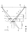
- the first and second signal lights 7 and 8 are projected obliquely, from different sides of a reference plane T as defined by a normal to the first object 1 surface and a direction (Y direction) perpendicular to the positional deviation detecting direction (X direction).
- the first and second signal lights are projected obliquely in the directions substantially symmetrical with respect to the reference plane T.
- Reference numerals 7' and 8' denote (unwanted) diffraction lights of predetermined orders related to the first and second signal lights 7 and 8.
- the first signal light 7 is provided by a (1, -1, 0)-th order light
- the second signal light 8 is provided by a (-1, 1, 0)-th order light
- the light 7' is provided by a (0, -1, 1)-th order light
- the light 8' is provided by a (0, 1, -1)-th order light.
- first and second detecting means for detecting the first and second signal lights 7 and 8, respectively.
- Each of the first and second detecting means comprises a one-dimensional (linear) CCD sensor, for example, having its sensing elements arrayed in the X-axis direction.
- the optical distance from the second object 2 to the first detecting means 11 or the second detecting means 12 is denoted by L.
- L the optical distance between the first and second objects 1 and 2
- f a1 and f a2 denote the focal lengths of the alignment marks 5 and 6
- Aa denotes the relative positional deviation of the first and second objects 1 and 2
- S 1 and S 2 denote displacements of the gravity center positions of the first and second signal lights on the first and second detecting means, respect- ivety, at that time, from the positions as assumed under correct alignment
- the alignment light inputted to the object 1 is a plane wave. The signs are such as illustrated.
- Each of the displacements S 1 and S 2 can be determined geometrically as a point of intersection between (i) the light receiving surface of the first (or second) detecting means 11 or 12 and (ii) the straight line that connects the focal point F 1 (F2) of the alignment mark 5 (6) and the optical axis center of the alignment mark 3 (4). Therefore, the opposability in direction of the displacements S 1 and S 2 of the gravity centers of these lights, responsive to a relative positional deviation of the first and second objects 1 and 2, is attainable by applying an inversive relationship to the signs of optical imaging magnifications of the alignment marks 3 and 4.
- examples that can be used as a lightsource are: a light source such as a semiconductor laser, a He-Ne laser, an Ar laser or the like that can emit a coherent light; and a light source such as a light emitting diode or the like that can emit an incoherent light.
- the (1, -1, 0)-th order light which is the lights 7 as well as the (-1, 1, 0)-th order light which is the light 8, are those lights: which are incident upon the alignment marks 5 and 6, respectively, on the mak 1 surface each at a predetermined angle; which are then transmissively diffracted by these marks and then reflectively diffracted by the alignment marks 3 and 4 on the wafer 2 surface, respect- i vely; and which are then incident on the detecting means 11 and 12, respectively.
- FIG 11 is a general and schematic view, as seen from the above, of an alignment pickup head 36 which accommodates in a single casing light sources 38 and 39, light projecting optical systems 30 and 31, mirrors 34 and 35, and light receiving optical systems 32 and 33, as well as the alignment marks 3 - 6 and the first and second lights 7 and 8.
- the first signal light 7 emanates from the light source 38 and, after passing the light projecting optical system 30 and the mirror 34, it is projected to the alignment mark 5 of the first object (mask) 1 at a predetermined angle.
- the second signal light 8 emanates from the light source 39 and, after passing the light projecting optical system 31 and the mirror 35, it is projected onto the alignment mark 6 of the first object 1 at a predetermined angle.
- the angles of incidence of the first and second lights 7 and 8 upon the first object are so set that, in order to prevent intersection of regularly reflected lights from the first object 1 surface as irradiated, the input lights to be projected to the first object 1 surface intersect, beforehand, with each other.
- the present embodiment is arranged so that only the (1, -1, 0)-th order light is received as the signal light.
- the conditions for impingement of the first and second alignment signal lights upon the first object 1 surface, the location and size of each alignment mark, the imaging condition for each of the first and second lights 7 and 8, and the like, are designed appropriately, to thereby assure avoidance of unwanted diffraction lights 7' and 8' or edge scattered light, from impinging on the detecting means 11 or 12.
- the first and second lights 7 and 8 are projected to the first object at angles substantially symmetrical with each other, with respect to the reference plane T, and the structure of the overall system is approximately symmetrical with respect to the reference plane T.
- the distance between the alignment marks 3 and 4 of the second object (as measured in the X direction) can be made small. As a result, the detection is not affected by any local waviness or distortion of the surface of the second object.
- the alignment marks 3, 4, 5 and 6 are provided by grating lenses, respectively. These grating lenses 5, 3, 6 and 4 have respective focal length which are denoted by f l , f 2 , f 3 and f 4 , respectively.
- the center position (optical axis position) of the alignment mark 3 of the second object as there is no relative positional deviation is denoted by (x W1 , y W1 , -g) and also that the alignment mark 3 is so designed as to form, at a position (x S1 , y si , z S1 ), an image of a point light source (point image) which is at a position (x M1 , y M1 , -f 1 ) if there is no positional deviation.
- the center position (optical axis position) of the alignment mark 6 of the first object is denoted by (x M02 , yMo2, 0), and the imaging point position of the parallel light by the alignment mark 6 is denoted by (x M2 , y M2 , -f 3 ).
- the center position (optical axis position) of the alignment mark 4 as there is no positional deviation is denoted by (x W2 , y w2 , -g) and that the mark 4 is so designed as to form, at a position (x S2 , y S2 , z S2 ), an image of a point light source (point image) which is at a position (x M2 , y M2 , -f 3 ) as there is no positional deviation.
- x M1 and x W1 are the quantities that are determined by the angles of deflection, with respect to the chief ray of input light, of the alignment marks of the first and second objects as well as the focal lengths of these marks, respectively, and they are expressed as follows:
- the detecting means has a light receiving zone with its center denoted by (0, y s , z S ) in the X-Y orthogonal coordinate system, and the light receiving zone has a rectangular shape of a size d 1 in the X direction and d 2 in the direction perpendicular thereto.
- the coordinate origin on the X axis is laid at the middle point between the alignment marks 5 and 6 on the first object (the middle of the segment connecting the centers of these alignment marks).
- Figure 12 is a schematic representation, showing a modified form of the third embodiment of the present invention.
- two alignment marks 3 and 4 provided on a second object (wafer) 2 are formed with overlapping, in a single and common region. This is effective to avoid a change, from a design value, of the relative distance in the X direction of the two, first and second lights 7 and 8 upon the first and second detecting means 11 and 12, which otherwise is caused by local inclination or waviness of the second object (wafer) 2 surface.
- This embodiment is so arranged that the first and second lights 7 and 8 emanating from the second object (wafer) 2 surface, are deflected and projected obliquely to the regions of the alignment marks 5 and 6 on the first object (mask) 1.
- the third embodiment of the present invention can be applied to a proximity type semiconductor device manufacturing apparatus such as shown in Figures 5A - 5C.
- the angle or direction of incidence of each of two lights upon the first object as well as the location or size of each alignment mark are so set as to satisfy the conditions defined by equations (31), (32) and (33).
- a position detecting system is featurized in that For detection of a relative positional deviation of first and second objects which are disposed opposed to each other, the first object is equipped with an alignment mark A1 having a wavefront converting function while the second object is equipped with an alignment mark B1 having a wavefront converting function, wherein the alignment mark B1 is formed in a region spaced from a region of the alignment markA1 of the first object as projected onto the second object, with respect to a direction substantially perpendicular to the positional deviation detecting direction.
- Light is projected from a light projecting means onto the first object in an oblique direction, and light influenced by the wavefront converting functions of the alignment marks A1 and B1 of the first and second objects is directed to a predetermined plane.
- the positions of incidence of these lights upon that plane are detected through a detecting means and, by using an output signal from the detecting means, the positional deviation is detected.
- two alignment marks A1 and A2 each having a wavefront converting function are provided on the first object, along the positional deviation detecting direction, while two alignment marks B1 and B2 each having a wavefront converting function are provided on the second object, along the positional deviation detecting direction and in a region spaced from a region of the alignment marks A1 and A2 of the first object as projected onto the second object, with respect to a direction substantially perpendicular to the positional deviation detecting direction.
- first light as influenced by the wavefront converting functions of the alignment marks A1 and B1 of the first and second objects as well as second light as influenced by the wavefront converting functions of the alignment marks A2 and B2 of the first and second objects are directed to a predetermined plane.
- the positions of incidence of the first and second lights on that plane are detected by detecting means and, by using output signal from the detecting means, the positional deviation is detected.
- each of the alignment marks A1, A2, B1 and B2 comprises a physical optic element having an imaging function in the positional deviation detecting direction.
- first and second (signal producing) alignment marks A1 and A2 each having a function of a physical optic element
- first and second (signal producing) alignment marks B1 and B2 similarly each having a function of a physical optic element, are formed.
- the region on the second object in which the two alignment marks B1 and B2 are formed is spaced by a predetermined distance from a region of the two alignment marks A1 and A2 of the first object as projected onto the second object, with respect to a direction substantially perpendicular to the positional deviation detecting direction.
- the alignment marks B1 and B2 are formed in that region, along the positional deviation detecting direction.
- Diffraction light from the alignment mark B1 is incident on a predetermined plane, and the gravity center of the incident light on that plane is detected by a first detecting means as the position of incidence of the first signal light.
- the term "gravity center of light” means such a point that, when on a light receiving surface a position vector of each point on the surface is multiplied by the light intensity of that point and the thus obtained products are integrated over the entire surface, the integrated level has a "zero vector * .
- the position of a peak point of the light intensity may be detected.
- the alignment marks A1, A2, B1 and B2 are so set that the gravity center position of the light incident on the first detecting means and the gravity center position of the light incident on the second detecting means, shift in opposite directions in response to a positional deviation between the objects A and B.
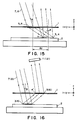
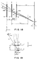
- Figure 13 is a perspective view of a major part of a fourth embodiment of the present invention.
- Figure 14 shows, in an extended view, a portion of the Figure 13 embodiment.
- Figure 15 is a sectional view of the Figure 13 embodiment, as seen in the X direction.
- denoted at 1 is a first object (object surface A) which is a mask, for example, and denoted at 2 is a second object (object surface B) which is a wafer, for example.
- object surface A which is a mask
- object surface B which is a wafer
- the illustrated is an example wherein a relative positional deviation of the first and second objects it to be detected.
- the first object is illustrated in duplication.
- Denoted at 5 and 3 are alignment marks which are provided on the first and second objects 1 and 2, respectively, for obtaining a first signal light.
- denoted at 6 and 4 are alignment marks provided on the first and second objects 1 and 2, respectively, for obtaining a second signal light.
- the paths are illustrated with the alignment marks 3 and 4 being replaced by equivalent transmission type alignment marks.
- Each of the alignment marks 3 - 6 comprises an optical member with wavefront converting function which serves as a physical optic element such as, for example, a grating lens having a one-dimensional ortwo-dimensional lens function or a diffraction grating having no lens function.
- the alignment marks 5 and 6 of the first object (mask) 1 are disposed along the positional deviation detecting direction (X direction).
- the alignment marks 3 and 4 of the second object (wafer) 2 are disposed in a region spaced, by a predetermined distance, from a region of the alignment marks 5 and 6 of the first object as being projected onto the second object 2 surface, with respect to a direction (Y direction) perpendicular to the positional deviation detecting direction, and they are disposed along the positional deviation detecting direction.
- Each of the alignment marks 3 - 6 comprises a grating lens with a cylindrical power, for example, having an imaging function with respect to the positional deviation detecting direction (X direction). With respect to the Y direction, each mark may have or may not have an imaging function.
- Reference numerals 7 and 8 denote the first and second (alignment) signal lights, while reference numerals 7' and 8' denote (unwanted) diffraction lights of predetermined orders related to the first and second signal lights 7 and 8.
- the first signal light 7 is provided by a (1, -1, 0)-th order light
- the second signal light 8 is provided by a (-1, 1, 0)-th order light
- the light 7' is provided by a (0, -1, 1)-th order light
- the light 8' is provided by a (0, 1, -1)-th order light.
- first and second detecting means for detecting the first and second signal lights 7 and 8, respectively.
- Each of the first and second detecting means comprises a one-dimensional (linear) CCD sensor, for example, having its sensing elements arrayed in the X-axis direction.
- the optical distance from the second object 2 to the first detecting means 11 or the second detecting means 12 is denoted by L.
- L the optical distance between the first and second objects 1 and 2
- f a1 and f a2 denote the focal lengths of the alignment marks 5 and 6
- Aa denotes the relative positional deviation of the first and second objects 1 and 2
- S 1 and S 2 denote displacements of the gravity center positions of the first and second signal lights on the first and second detecting means, respect- i vely, at that time, from the positions as assumed under correct alignment
- the alignment light inputted to the object 1 is a plane wave. The signs are such as illustrated.
- Each of the displacements S 1 and S 2 can be determined geometrically as a point of intersection between (i) the light receiving surface of the first (or second) detecting means 11 or 12 and (ii) the straight line that connects the focal point F 1 (F 2 of the alignment mark 5 (6) and the optical axis center of the alignment mark 3 (4). Therefore, the opposability in direction of the displacements S 1 and S 2 of the gravity centers of these lights, responsive to a relative positional deviation of the first and second objects 1 and 2, is attainable by applying an inversive relationship to the signs of optical imaging magnifications of the alignment marks 3 and 4.
- examples that can be used as a lightsource are: a light source such as a semiconductor laser, a He-Ne laser, an Ar laser or the like that can emit a coherent light; and a light source such as a light emitting diode or the like that can emit an incoherent light.
- the (1, -1, 0)-th order light which is the lights 7 as well as the (-1, 1, 0)-th order light which is the light 8, are those lights: which are incident upon the alignment marks 5 and 6, respectively, on the mask 1 surface each at a predetermined angle; which are then transmissively diffracted by these marks and then reflectively diffracted by the alignment marks 3 and 4 on the wafer 2 surface, respectively; and which are then incident on the detecting means 11 and 12, respectively.
- the (0, -1, 1)-th order light which is thp light 7' as well as the (0, 1, -1)-th order light which is the light 8' are those lights: which are transmitted atzero-th order by the alignment marks 5 and 6 on the mask 1; which are then reflectively diffracted by the alignment marks 3 and 4 on the wafer 2 surface, respectively; and which are then transmissively diffracted by the alignment marks 5 and 6 on the mask 1 surface and incident on the detecting means 11 and 12.
- the gravity center positions of the first and second alignment lights, respectively, incident on the respective detecting means are detected and, by using output signals from the detecting means 11 and 12, any positional deviation of the mask 1 and the wafer 2 can be detected.
- the alignment mark disposition in the Y direction perpendicular to the positional deviation detecting direction is so setthat, within the positional deviation measurement range after the preali- gnment operation, as shown in Figure 15, the central position of the alignment marks 3 and 4 of the second object 2 is always deviated by a predetermined distance dy, with respect to the alignment marks 5 and 6 of the first object, in a direction (Y direction) perpendicular to the positional deviation detecting direction, this being done so as to avoid impingement of zero-th order light transmitted through the alignment marks 5 and 6 of the first object 1 upon the alignment marks 3 and 4 of the second object 2.
- the distance dy is a parameter to be determined in dependence upon the width of each alignment mark in the Y direction and the incidence angle ⁇ .
- the distance dy is so determined as to avoid generation of the (0, -1,1 )-th order diffraction light 7' and the (0, 1, -1)-th order diffraction light 8' but to allow impingement of only the (1, -1, 0)-th order light 7 and the (-1, 1, 0)-th order light 8 upon the detecting means 11 and 12.
- the distance dy may be determined from the condition that, of the light transmitted at zero-th orderthrough the first object 1, the light diffracted at negative first order by a positive Y-direction side edge e in the Y-Z section of the alignment marks 3 and 4 of the second object 2 does not impinge on the region of the alignment marks 5 and 6 on the first object 1 surface.
- the widths in the Y direction of the alignment marks 5 and 3 of the first and second objects are denoted by Wy M and Wy W
- the center positions of the alignment marks 5 and 3 of the first and second objects, respectively, in the Y direction are denoted by y0 M and y0 W
- the pitches (constant) of the alignment marks of the first and second objects, in the Y direction are denoted by P M and P w
- the position e of the edge of the alianment mark can be expressed as:
- condition to be detected is: wherein ⁇ is the emission angle in the Y-Z plane of the negative first order diffraction light, with respect to a normal to the second object 2 surface, and it can be determined in accordance with a diffraction condition such as follows:
- the alignment mark disposition is so determined as to satisfy the conditions given by equations (42') and (43) and, by doing so, only the (1, -1, 0)-th order light and the (-1, 1, 0)-th order light can be received by the detecting means and unwanted crosstalk with the (0, -1,1)-th order light or the (0,1, -1)-th order light can be avoided.
- the fourth embodiment of the present invention is applicable to a proximity type semiconductor device manufacturing exposure apparatus such as shown in Figures 5A - 5C.
- Figure 16 is a schematic view showing a modified form of the fourth embodiment of the present invention.
- Each of the alignment marks 3 - 6 has an imaging function with respect to the X direction.
- the alignment light7 (8) is projected from a light projecting means (notshown) obliquely only the mask 1 surface, at a predetermined angle in the Y-Z plane.
- the light is projected to a region on the mask 1 surface in which the alignment mark 5 (6) is not present.
- the light passed (transmitted at zero-th order) through the mask 1 is reflective diffracted by the alignment mark 3 (4) on the wafer 2 surface and, then, it is diffracted by the alignment mark 5 (6) on the mask 1 surface.
- the thus diffracted light 7 (8) is detected by the detecting means 11 (12).
- the phenomenon that the spacing in the X direction of the gravity center positions on two light detecting means changes in proportion to the relative positional deviation in the X direction of a first object (mask) and a second object (wafer) is used, and the change in the spacing is detected.
- the present invention is not limited to this.
- the invention is applicable also to an arrangement wherein the relative positional deviation of the mask and the wafer is detected on the basis of proportional relationship between (i) the quantity of deviation of the gravity center position of the diffraction light upon a single detecting means, from a preset reference position thereon, and (ii) the quantity of relative positional deviation of the mask and the wafer.
- system may be modified so that the two signal lights are received by a common detecting means.
- a position detecting system is featurized in that: For detection of a relative positional deviation of first and second object which are disposed opposed to each other, the first object is equipped with two alignment marks A1 and A1' each having a wavefront converting function which marks are provided along a direction substantially perpendicular to the positional deviation detecting direction, while the second object is equipped with an alignment mark B1 having a wavefront converting function.
- the light as influenced by transmissive type wavefront converting function of the alignment mark A1 of the first object, as influenced by the reflective type wavefront converting function of the alignment mark B1 of the second object and then as influenced by transmission type wavefront converting function of the alignment mark A1' of the first object, is directed to a predetermined plane.
- the position of incidence of the light on that plane is detected through a detecting means and, by using an output signal from the detecting means, the positional deviation is detected.
- this embodiment of the present invention is featurized in that: Various features are so set that the alignment mark B1 is positioned in a region outside a region in which the light, of the light from the light projecting means, as inputted to the alignment mark A1' of the first object and influenced by the transmission type wavefront converting function thereof, is inputted to the second object. Or, the region in which the light, of the lightfrom the light projecting means, as inputted to the alignment markA1' ofthe first object and influenced by transmission type wavefront converting function thereof impinges on the second object, overlaps the region of the second object in which the alignment mark B1 is formed, and the area of such overlapping region is not greater than 30 % of the region in which the alignment mark B1 is formed. Various factors are so set.
- first and second signal producing alignment marks A1, A1' and A2, A2' each having a function of a physical optic element
- first and second signal producing alignment marks B1 and B2 similarly each having a function of a physical optic element
- the first signal producing aligment marks A1 and A1' are provided along a direction substantially perpendicular to the positional deviation detecting direction.
- the second signal producing alignment marks A2 and A2' are provided along a direction substantially perpendicular to the positional deviation detecting direction.
- Parallel light having a Gaussian intensity distribution is inputted to the alignment mark A1, and diffraction light caused thereby is inputted to the alignment mark B1.
- Diffraction lightfrom the alignment mark B1 is inputted to the alignment markA', and diffraction light therefrom is incident on a predetermined plane.
- the gravity center of the incident light on that plane is detected by a first detecting means as the position of incidence of the first signal light.
- the term "gravity center of light” means such a point that, when on a light receiving surface a position vector of each point on the surface is multiplied by the light intensity of that point and the thus obtained products are integrated over the entire surface, the integrated level has a "zero vector".
- the position of a peak point of the light intensity may be detected.
- the alignment marks A1, A1', A2, A2', B1 and B2 are so set that the gravity center position of the light incident on the first detecting means and the gravity center position of the light incident on the second detecting means, shift in opposite directions in response to a positional deviation between the objects A and B.
- Figure 17 is a perspective view of a major part of the fifth embodiment of the present invention.
- Figure 18 illustrates, in an extended view, a portion of the Figure 17 embodiment.
- Figure 19 is a schematic view of a major part of the Figure 17 embodiment, as seen in the X direction.
- denoted at 1 is a first object (object surface A) which is a mask, for example, and denoted at 2 is a second object (object surface B) which is a wafer, for example.
- object surface A which is a mask
- object surface B which is a wafer
- the illustrated is an example wherein a relative positional deviation of the first and second objects it to be detected.
- the first object is illustrated in duplication.
- Denoted at 5, 5' and 3 are alignment marks which are provided on the first and second objects 1 and 2, respectively, for obtaining a first signal light.
- denoted at 6, 6' and 4 are alignment marks provided on the first and second objects 1 and 2, respectively, for obtaining a second signal light.
- the paths are illustrated with the alignment marks 3 and 4 being replaced by equivalent transmission type alignment marks.
- Each of the alignment marks 3 - 6' comprises an optical member with wavefront converting function which serves as a physical optic elementsuch as, forexample, a grating lens having a one-dimensional ortwo-dimensional lens function or a diffraction grating having no lens function.
- the alignment marks 5 and 5' are disposed along a direction (Y direction) substantially perpendicular to the positional deviation detecting direction (X direction).
- the alignment marks 6 and 6' are disposed along a direction (Y direction) substantially perpendicular to the positional deviation detecting direction (X direction).
- the X direction coincides with a wafer scribe line direction.
- each alignment mark of the first and second objects has an imaging function in the X direction. With respect to a direction perpendicular thereto, it may have or it may not have an imaging function.
- Reference numerals 7 and 8 denote the first and second (alignment) signal lights, while reference numerals 7' and 8' denote (unwanted) diffraction lights of predetermined orders related to the first and second signal lights 7 and 8.
- first and second detecting means for detecting the first and second signal lights 7 and 8, respectively.
- Each of the first and second detecting means comprises a one-dimensional (linear) CCD sensor, for example, having its sensing elements arrayed in the X-axis direction.
- first and second signal lights 7 and 8 Since the optical actions of the first and second signal lights 7 and 8 are substantially the same and they are handled substantially in the same manner, description will be made only with regard to the first signal light 7.
- the spacing between the first object (which hereinafter will be referred to also as “mask”) 1 and the second object (which hereinafter will be referred to also as “wafer”) 2 is denoted by g
- the distance from the second object 2 to the convergent point P2 as defined by the alignment mark 3 of the second object 2 is denoted by L 1
- the distance from the first object 1 to the first detecting means 11 is denoted by L 2 .
- the position S of incidence of the (m, n, f)-th order light on the detecting means surface 11a is expressed by using the incidence angle 8 of light in the X-Z plane and the X-axis center positions x M0 , x mo ' and x w of the alignment marks 5. 3 and 5', as follows:
- L 2 is given by:
- focal length fl M (fm M )
- equation (52) is substituted into the positional deviation sensitivity ⁇ as given by equation (51), then it follows that
- the positional deviation sensitivity ⁇ as obtainable by substituting equation (56) into equation (51'), is determined by fm M , fn w , fl M and g.
- the light 7 diffracted or wavefront-converted three times, by two alignment marks 5 and 5' of the first object 1 and one alignment mark 3 of the second object 2, is used as the positional deviation detecting light.
- two lights having different diffraction histories emanate in the same direction.
- alignment marks 5 and 5' are formed on the first object 1 while an alignment mark 3 is formed on the second object 2.
- the first signal light 7 the (m, n, f)-th order light as projected onto the first object 1 at an angle a and diffracted at m-th order by the alignment mark 5, at n-th order by the alignment mark 3 and at f -th order by the alignment mark 5', is used.
- the (f, n, m)-th order light 7' diffracted at f-th order by the alignment mark 5' of the first object 1, at n-th order by the alignment mark 3 of the second object 2 and at m-th order by the alignment mark 5 of the first object 1, emanates from the first object 1 in the same direction as the first signal light 7.
- the pair of alignment marks 5 and 5' of the first object 1 and the pair of alignment marks 6 and 6' are disposed along a direction (Ydirection) perpendicular to the positional deviation detecting direction (X direction), and each alignment mark is provided by a cylindrical grating lens having an imaging function only in the X direction.
- the alignment marks 5, 3, 6 and 4 each has a mark pattern which is configured so that it serves as a grating element of constant pitch in the Y direction.
- the alignment marks 5' and 6' each is provided by a grating lens of linear zone plate type, having no light deflecting function in the Y-Z section.
- the grating pitch of the alignment mark in the Y-Z section namely, the section in which it has no imaging function
- P, and P 2 for the alignment marks 5 and 3
- P 3 and P 4 for the alignment marks 6 and 4
- the signal light is provided by the (-1, 1, -1)-th order light produced as a result of impingement of light upon the first object surface at an angle and diffraction through these alignment marks at negative first order by the alig nment mark 5 (6), at positive first order by the alignment marks 3 (4) and at negative first order by the alignment mark 5' (6'), in this order, if the angles of lights in the Y-Z plane emanating from the alignment marks 5, 3, 6 and 4 are denoted by ⁇ (P 1 ), ⁇ (P 3 ), ⁇ (P 2 ) and y(P 4
- the angle ⁇ is made small while the angle y is made larger than the incidence angle a.
- a 5 deg.
- Equation (57) is a condition for avoiding impingement of the light 7' upon the detection surface, where in Figure 20 the light 7 is used as the first signal light Equation (58) is a condition related to the size and location of each alignment mark for assuring efficient impingement of the first signal light 7 upon the detection surface.
- the position of incidence of the first signal light 7 (second signal light 8) can be detected without being affected by the light 7' (light 8').
- the present embodiment is applicable also to a proximity type semiconductor device manufacturing exposure apparatus such as shown in Figures 5A - 5C.
- Figure 21 is a schematic view of a major part of a modified form of the fifth embodiment of the present invention.
- two alignment marks 5 and 5' each comprising a physical optic element are provided on the first object (mask) 1, while one alignment mark 3 comprising a physical optic element is provided on the second object (wafer) 2.
- two alignment marks 6 and 6' each comprising a physical optic element are provided on the first object 1, while one alignment mark 4 (not shown) comprising a physical optic element is provided on the second object 2.
- Each alignment mark has an imaging function in the X direction, and is provided by a cylindrical type lens element having a light deflecting function in the Y direction.
- the production of the light 7' which is an unwanted diffraction light in relation to the first signal light 7, is reduced.
- the location and size of each alignment mark in the Y-Z plane as well as the light paths, particularly, the diffraction angle of each alignment mark are so set that the quantity of the light 7' becomes not greater than 1/20 of the quantity of the first signal light 7.
- the positional deviation detecting direction lies in the X direction, that in the Y-Z plane light is incident on the first object at an angle a with respect to a normal thereto, and that the first signal light 7 having a path such as shown in Figure 21 is incident on the detecting means 11 which may comprise a CCD or accumulation type photoelectric transducer element.
- the orders of diffraction by the alignment marks are such that the light is diffracted at m-th order by the alignment mark 5, at n-th order by the alignment mark 3 and at f-th order by the alignment mark 5'. Namely, it is the (m, n, t)-th order light.
- the light 7' which is unwanted diffraction light is expressed as the (m', n', l')-th order light, as diffracted at m'-th order by the alignment mark 5', at n'-th order by the alignment mark 3 and at f'-th order by the alignment mark 5.
- the factors are so set that the area of overlapping region between the region in which the (m', n', f')-th order light 7' impinges on the second object 2 surface and the region in which the alignment mark 3' is formed, becomes not greater than 30 % of the area of the region of the alignment mark 3'. This assures that the intensity of the light 7' is reduced to one-third or lower of the intensity of the light 7.
- the (1, 1, -1)-th order light is used as the first signal light 7 and, in consideration of the off-axis imaging characteristics as given by equation (51') of the wavefront converting characteristics of the grating lens patterns of the alignment marks 5, 5' and 3, the optical system is arranged so that the predetermined imaging plane provides the detection surface.
- the light 7 ' which can impinge and converge on the light receiving zone of the detection surface in response to the (1, 1, -1)-th order light which is the first signal light is the (-1, 1, 1)-th order light.
- the (f, n, m)-th order light impinges and converges upon the detection surface.
- Each alignment mark has an imaging characteristic in the X direction, but it has no imaging function in the Y direction. Totally, it has a light deflecting function for changing the emission angle of the light toward a predetermined direction.
- the grating pitches (regular) of the alignment marks 5, 5' and 3 in the Y direction are P 1 , P 1 ' and P 2 , that the emission angle in the Y-Z plane of the light 7 from the alignment mark 5 is ⁇ , as shown in Figure 21, that the emission angle from the alignment mark 3 is y, and that the emission angle from the alignment mark 5' is 8.
- the center coordinate positions of the alignment marks 5, 5' and 3 in the Y direction are y 1.0 , y 20 and y 3 . 0 , and that the boundary positions of them in the Y direction are e 1 , e 2 , ... and eo, as illustrated.
- e 2 is the contact boundary position of the alignment marks 5 and 5'. If the spacing between the first and second objects 1 and 2 in the Z direction is g, then the emission angle y' of the light 7 from the alignment mark 5' is expressed in the following relation:
- condition for avoiding impingement of a portion of the light 7', emanating from the boundary e 1 portion of the alignment mark 5', upon the alignment mark 3 forming region on the second object is given by:
- equation (60) represents the condition for suppressing production of the light 7'.
- condition for assuring efficient impingement of the light 7, emanating from the alignment mark 5, upon the alignment mark 3 is:
- Equations (61) and (62) are the conditions with which, when the system is structured so that, as the light 7 is wavefront converted by the object surfaces totally, the region of incidence of the light upon each alignment mark is defined about an axis of the center of each alignment mark, any light directed outwardly of such an alignment mark region is minimized. Namely, these equations are the conditions related to the location and size of each alignment mark as well as the optical path designing, necessary for assuring efficient transmission of wavefront and, thus, for enhancing the quantity of light impinging on the detection surface.
- the phenomenon that the spacing in the X direction of the gravity center positions on two light detecting means changes in proportion to the relative positional deviation in the X direction of a first object (mask) and a second object (wafer) is used, and the change in the spacing is detected.
- the present invention is not limited to this.
- the invention is applicable also to an arrangement wherein the relative positional deviation of the mask and the wafer is detected on the basis of proportional relationship between (i) the quantity of deviation of the gravity center position of the diffraction light upon a single detecting means, from a preset reference position thereon, and (ii) the quantity of relative positional deviation of the mask and the wafer.
Landscapes
- Physics & Mathematics (AREA)
- General Physics & Mathematics (AREA)
- Exposure And Positioning Against Photoresist Photosensitive Materials (AREA)
- Length Measuring Devices By Optical Means (AREA)
Applications Claiming Priority (10)
| Application Number | Priority Date | Filing Date | Title |
|---|---|---|---|
| JP115445/90 | 1990-05-01 | ||
| JP11544590A JP2867597B2 (ja) | 1990-05-01 | 1990-05-01 | 位置検出方法 |
| JP2272926A JPH04148810A (ja) | 1990-10-11 | 1990-10-11 | 位置検出装置 |
| JP2272928A JPH04148812A (ja) | 1990-10-11 | 1990-10-11 | 位置検出装置 |
| JP272926/90 | 1990-10-11 | ||
| JP272927/90 | 1990-10-11 | ||
| JP272929/90 | 1990-10-11 | ||
| JP2272927A JPH04148811A (ja) | 1990-10-11 | 1990-10-11 | 位置検出装置 |
| JP2272929A JPH04148813A (ja) | 1990-10-11 | 1990-10-11 | 位置検出装置 |
| JP272928/90 | 1990-10-11 |
Publications (3)
| Publication Number | Publication Date |
|---|---|
| EP0455443A2 true EP0455443A2 (de) | 1991-11-06 |
| EP0455443A3 EP0455443A3 (en) | 1992-07-08 |
| EP0455443B1 EP0455443B1 (de) | 1997-11-12 |
Family
ID=27526690
Family Applications (1)
| Application Number | Title | Priority Date | Filing Date |
|---|---|---|---|
| EP91303846A Expired - Lifetime EP0455443B1 (de) | 1990-05-01 | 1991-04-29 | Verfahren und Apparat zur Detektion von Lageabweichungen |
Country Status (3)
| Country | Link |
|---|---|
| US (1) | US5481363A (de) |
| EP (1) | EP0455443B1 (de) |
| DE (1) | DE69128164T2 (de) |
Cited By (2)
| Publication number | Priority date | Publication date | Assignee | Title |
|---|---|---|---|---|
| EP1001301A3 (de) * | 1998-11-09 | 2001-06-27 | Canon Kabushiki Kaisha | Optisches Element mit Justiermarke und optisches System mit einem solchen Element |
| CN114051458A (zh) * | 2019-06-24 | 2022-02-15 | 奇跃公司 | 聚合物图案化磁盘堆叠制造 |
Families Citing this family (9)
| Publication number | Priority date | Publication date | Assignee | Title |
|---|---|---|---|---|
| JP3368017B2 (ja) * | 1993-10-29 | 2003-01-20 | キヤノン株式会社 | 位置検出装置及びそれを用いた半導体素子の製造方法 |
| JPH07135168A (ja) * | 1993-11-11 | 1995-05-23 | Canon Inc | アライメント方法及びそれを用いた位置検出装置 |
| JPH1022213A (ja) * | 1996-06-28 | 1998-01-23 | Canon Inc | 位置検出装置及びそれを用いたデバイスの製造方法 |
| JPH11241908A (ja) | 1997-12-03 | 1999-09-07 | Canon Inc | 位置検出装置及びそれを用いたデバイスの製造方法 |
| US6724479B2 (en) * | 2001-09-28 | 2004-04-20 | Infineon Technologies Ag | Method for overlay metrology of low contrast features |
| US7573580B2 (en) | 2003-11-17 | 2009-08-11 | Asml Holding N.V. | Optical position measuring system and method using a low coherence light source |
| CN101206995B (zh) * | 2006-12-20 | 2010-05-19 | 中芯国际集成电路制造(上海)有限公司 | 监测晶圆托盘平整性的方法 |
| JP5812599B2 (ja) * | 2010-02-25 | 2015-11-17 | キヤノン株式会社 | 情報処理方法及びその装置 |
| CN109373892A (zh) * | 2018-08-14 | 2019-02-22 | 武汉船用机械有限责任公司 | 一种基于机器视觉的辅助划线系统及其运行方法 |
Family Cites Families (9)
| Publication number | Priority date | Publication date | Assignee | Title |
|---|---|---|---|---|
| US4037969A (en) * | 1976-04-02 | 1977-07-26 | Bell Telephone Laboratories, Incorporated | Zone plate alignment marks |
| US4326805A (en) * | 1980-04-11 | 1982-04-27 | Bell Telephone Laboratories, Incorporated | Method and apparatus for aligning mask and wafer members |
| US4514858A (en) * | 1983-03-15 | 1985-04-30 | Micronix Partners | Lithography system |
| DE3853246T2 (de) * | 1987-09-25 | 1995-06-29 | Matsushita Electric Industrial Co., Ltd., Kadoma, Osaka | Vorrichtung zur Kontrolle des Lageverhältnisses zwischen einer Photomaske und einem Plättchen. |
| JP2546364B2 (ja) * | 1988-02-16 | 1996-10-23 | キヤノン株式会社 | 位置合わせ装置 |
| DE68929270T2 (de) * | 1988-09-09 | 2001-05-23 | Canon K.K., Tokio/Tokyo | Vorrichtung und Gerät zur Positionsdetektion |
| EP0358511B1 (de) * | 1988-09-09 | 2001-07-18 | Canon Kabushiki Kaisha | Vorrichtung zur Detektion der Positionsrelation zwischen zwei Objekten |
| JP2704002B2 (ja) * | 1989-07-18 | 1998-01-26 | キヤノン株式会社 | 位置検出方法 |
| US5225892A (en) * | 1990-02-05 | 1993-07-06 | Canon Kabushiki Kaisha | Positional deviation detecting method |
-
1991
- 1991-04-29 EP EP91303846A patent/EP0455443B1/de not_active Expired - Lifetime
- 1991-04-29 DE DE69128164T patent/DE69128164T2/de not_active Expired - Fee Related
-
1994
- 1994-05-13 US US08/242,066 patent/US5481363A/en not_active Expired - Fee Related
Cited By (5)
| Publication number | Priority date | Publication date | Assignee | Title |
|---|---|---|---|---|
| EP1001301A3 (de) * | 1998-11-09 | 2001-06-27 | Canon Kabushiki Kaisha | Optisches Element mit Justiermarke und optisches System mit einem solchen Element |
| US6856392B1 (en) | 1998-11-09 | 2005-02-15 | Canon Kabushiki Kaisha | Optical element with alignment mark, and optical system having such optical element |
| CN114051458A (zh) * | 2019-06-24 | 2022-02-15 | 奇跃公司 | 聚合物图案化磁盘堆叠制造 |
| EP3986718A4 (de) * | 2019-06-24 | 2022-09-14 | Magic Leap, Inc. | Herstellung eines polymergemusterten plattenstapels |
| US12038591B2 (en) | 2019-06-24 | 2024-07-16 | Magic Leap, Inc. | Polymer patterned disk stack manufacturing |
Also Published As
| Publication number | Publication date |
|---|---|
| DE69128164D1 (de) | 1997-12-18 |
| US5481363A (en) | 1996-01-02 |
| DE69128164T2 (de) | 1998-04-02 |
| EP0455443B1 (de) | 1997-11-12 |
| EP0455443A3 (en) | 1992-07-08 |
Similar Documents
| Publication | Publication Date | Title |
|---|---|---|
| EP0411966B1 (de) | Verfahren und Vorrichtung zur Positionsbestimmung | |
| US5200800A (en) | Position detecting method and apparatus | |
| US5162656A (en) | Position detecting device employing marks and oblique projection | |
| US4390279A (en) | Alignment device in an IC projection exposure apparatus | |
| US5481363A (en) | Positional deviation detecting method | |
| US5225892A (en) | Positional deviation detecting method | |
| US5235408A (en) | Position detecting method and apparatus | |
| EP0468741B1 (de) | Positionsbestimmungsmethode | |
| US5160848A (en) | Device for detecting the relative position between opposed first and second objects | |
| US5325176A (en) | Position detecting method and apparatus including Fraunhofer diffraction detector | |
| US5495336A (en) | Position detecting method for detecting a positional relationship between a first object and a second object | |
| US5291023A (en) | Position detecting system utilizing a weight coefficient to determine a gravity center of light | |
| EP0336537A1 (de) | Vorrichtung zum Nachweis der örtlichen Beziehung zwischen zwei Objekten | |
| US5294980A (en) | Positioning detecting method and apparatus | |
| EP0358425A2 (de) | Verfahren und Vorrichtung zur Positionsdetektion | |
| JPH07130636A (ja) | 位置検出装置及びそれを用いた半導体素子の製造方法 | |
| US5455679A (en) | Position detecting system | |
| US5229617A (en) | Position detecting method having reflectively scattered light prevented from impinging on a detector | |
| US5148035A (en) | Position detecting method and apparatus | |
| EP0329433A2 (de) | Verfahren und Vorrichtung zur Feststellung der Lage | |
| JP2513300B2 (ja) | 位置検出装置 | |
| EP0441578B1 (de) | Verfahren zur Detektion von Lageabweichungen | |
| JP2867597B2 (ja) | 位置検出方法 | |
| EP0455446B1 (de) | Verfahren und Vorrichtung zur Positionsdetektion | |
| JP2775988B2 (ja) | 位置検出装置 |
Legal Events
| Date | Code | Title | Description |
|---|---|---|---|
| PUAI | Public reference made under article 153(3) epc to a published international application that has entered the european phase |
Free format text: ORIGINAL CODE: 0009012 |
|
| AK | Designated contracting states |
Kind code of ref document: A2 Designated state(s): DE FR GB NL |
|
| PUAL | Search report despatched |
Free format text: ORIGINAL CODE: 0009013 |
|
| AK | Designated contracting states |
Kind code of ref document: A3 Designated state(s): DE FR GB NL |
|
| 17P | Request for examination filed |
Effective date: 19921125 |
|
| 17Q | First examination report despatched |
Effective date: 19950223 |
|
| GRAG | Despatch of communication of intention to grant |
Free format text: ORIGINAL CODE: EPIDOS AGRA |
|
| GRAH | Despatch of communication of intention to grant a patent |
Free format text: ORIGINAL CODE: EPIDOS IGRA |
|
| GRAH | Despatch of communication of intention to grant a patent |
Free format text: ORIGINAL CODE: EPIDOS IGRA |
|
| GRAA | (expected) grant |
Free format text: ORIGINAL CODE: 0009210 |
|
| AK | Designated contracting states |
Kind code of ref document: B1 Designated state(s): DE FR GB NL |
|
| PG25 | Lapsed in a contracting state [announced via postgrant information from national office to epo] |
Ref country code: FR Free format text: LAPSE BECAUSE OF FAILURE TO SUBMIT A TRANSLATION OF THE DESCRIPTION OR TO PAY THE FEE WITHIN THE PRESCRIBED TIME-LIMIT Effective date: 19971112 |
|
| REF | Corresponds to: |
Ref document number: 69128164 Country of ref document: DE Date of ref document: 19971218 |
|
| EN | Fr: translation not filed | ||
| PLBE | No opposition filed within time limit |
Free format text: ORIGINAL CODE: 0009261 |
|
| STAA | Information on the status of an ep patent application or granted ep patent |
Free format text: STATUS: NO OPPOSITION FILED WITHIN TIME LIMIT |
|
| 26N | No opposition filed | ||
| REG | Reference to a national code |
Ref country code: GB Ref legal event code: IF02 |
|
| PGFP | Annual fee paid to national office [announced via postgrant information from national office to epo] |
Ref country code: NL Payment date: 20040415 Year of fee payment: 14 Ref country code: GB Payment date: 20040415 Year of fee payment: 14 |
|
| PGFP | Annual fee paid to national office [announced via postgrant information from national office to epo] |
Ref country code: DE Payment date: 20040421 Year of fee payment: 14 |
|
| PG25 | Lapsed in a contracting state [announced via postgrant information from national office to epo] |
Ref country code: GB Free format text: LAPSE BECAUSE OF NON-PAYMENT OF DUE FEES Effective date: 20050429 |
|
| PG25 | Lapsed in a contracting state [announced via postgrant information from national office to epo] |
Ref country code: NL Free format text: LAPSE BECAUSE OF NON-PAYMENT OF DUE FEES Effective date: 20051101 Ref country code: DE Free format text: LAPSE BECAUSE OF NON-PAYMENT OF DUE FEES Effective date: 20051101 |
|
| GBPC | Gb: european patent ceased through non-payment of renewal fee |
Effective date: 20050429 |
|
| NLV4 | Nl: lapsed or anulled due to non-payment of the annual fee |
Effective date: 20051101 |