EP0455467B1 - Farbdrucker - Google Patents
Farbdrucker Download PDFInfo
- Publication number
- EP0455467B1 EP0455467B1 EP91303909A EP91303909A EP0455467B1 EP 0455467 B1 EP0455467 B1 EP 0455467B1 EP 91303909 A EP91303909 A EP 91303909A EP 91303909 A EP91303909 A EP 91303909A EP 0455467 B1 EP0455467 B1 EP 0455467B1
- Authority
- EP
- European Patent Office
- Prior art keywords
- data
- color
- print data
- printer
- input
- Prior art date
- Legal status (The legal status is an assumption and is not a legal conclusion. Google has not performed a legal analysis and makes no representation as to the accuracy of the status listed.)
- Expired - Lifetime
Links
Images


Classifications
-
- G—PHYSICS
- G06—COMPUTING OR CALCULATING; COUNTING
- G06K—GRAPHICAL DATA READING; PRESENTATION OF DATA; RECORD CARRIERS; HANDLING RECORD CARRIERS
- G06K15/00—Arrangements for producing a permanent visual presentation of the output data, e.g. computer output printers
-
- G—PHYSICS
- G06—COMPUTING OR CALCULATING; COUNTING
- G06K—GRAPHICAL DATA READING; PRESENTATION OF DATA; RECORD CARRIERS; HANDLING RECORD CARRIERS
- G06K2215/00—Arrangements for producing a permanent visual presentation of the output data
- G06K2215/0002—Handling the output data
- G06K2215/004—Generic data transformation
-
- G—PHYSICS
- G06—COMPUTING OR CALCULATING; COUNTING
- G06K—GRAPHICAL DATA READING; PRESENTATION OF DATA; RECORD CARRIERS; HANDLING RECORD CARRIERS
- G06K2215/00—Arrangements for producing a permanent visual presentation of the output data
- G06K2215/0002—Handling the output data
- G06K2215/0062—Handling the output data combining generic and host data, e.g. filling a raster
- G06K2215/0071—Post-treatment of the composed image, e.g. compression, rotation
-
- G—PHYSICS
- G06—COMPUTING OR CALCULATING; COUNTING
- G06K—GRAPHICAL DATA READING; PRESENTATION OF DATA; RECORD CARRIERS; HANDLING RECORD CARRIERS
- G06K2215/00—Arrangements for producing a permanent visual presentation of the output data
- G06K2215/0082—Architecture adapted for a particular function
- G06K2215/0094—Colour printing
Definitions
- the present invention relates to a printer which has at least two print colors and is especially capable of outputting in a desired print color.
- a conventional multicolor printer has a plurality of bit map memories corresponding to colors which are to be developed, and is so constructed that each color of image data input from the host equipment is developed into the respective bit map memories.
- the above conventional technique has a defect in which the color output function of the printer cannot be fully utilized because when the input data is single color data such as a list for control information, it forcibly outputs only in black or prints using one basic color since color designation is completely entrusted to the host equipment side.
- a sender of printing data that is, a host computer, includes in its output data a control code for designating a color out of print colors available for the printer.
- Japanese Patent Abstract No. JP-A-63-288562 which is used for the delimitation of claims 1 and 6 discloses a printer capable of printing characters and non-characters in two different colors.
- the above color modulation data is a color pattern data to dither modulate each color element, for example.
- An embodiment of the present invention improves on conventional techniques and enables a printer capable of printing a multicolor image intended by an operator whilst receiving the single color print information.
- Fig. 1 is a block diagram showing a configuration of a printer which can convert an input single color data into a multicolor data.
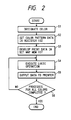
- Fig. 2 is a flow chart showing an operation in the configuration in Fig. 1.
- Fig. 3 is a block diagram showing a configuration of the first embodiment to set a desired color in an input single color data as the output data.
- Figs. 4A and 4E show examples of format for respective color designation tables.
- Fig. 5 shows an example of format for print data received by the printer.
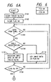
- Fig. 6 is a flow chart showing the operation of the CPU in the first embodiment.
- Fig. 7 is a block diagram showing the configuration of a printer of a second embodiment to set a desired output color.
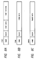
- Figs. 8A to 8C show examples of data format for a registration area.
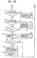
- Fig. 9 is a flow chart showing an operation of the CPU in the second embodiment.
- Fig. 1 is a block diagram showing a configuration of a printer to output by converting an input single color data into a multicolor data.
- a timing circuit 101 interfaces with a printing unit (not shown) to control a series of operations of this printer.
- a color pattern register 102 stores color pattern data, on the basis of which dither modulation is performed.
- dither pattern data for four colors: yellow (Y), magenta (M), cyan (C) and black (K) are used for dither modulation.
- the color pattern register 102 has data blocks for four colors: Y, M, C and K, and each block has a structure of 16 bit x 16 bit, for example.
- the above color pattern data for each color have been prepared in a plurality of types, and stored in a ROM (not shown). These data are selected in accordance with the operator's instruction, and are written in the register 102 through a bus 103. The register 102 outputs in order these pattern data for each color thus developed into a bus 105 in accordance with a control signal 104 from the timing circuit 101.
- An arithmetic circuit 106 is an AND circuit, in which an AND operation of an image data, which is input from the bit map memory 107 through a bus 108, with the color pattern data is performed.
- the arithmetic circuit 106 outputs an image data modulated by the color pattern data to a printer interface unit 110 through a bus 109.
- a signal 111 is a synchronizing signal to the printer interface unit 110
- a signal 112 is a synchronizing signal from the printing unit
- a signal 113 is an image data signal to the printing unit.
- Fig. 2 is a flow chart showing the operation in the embodiment according to the present invention.
- the operator first designates color using a command, etc. for a data without color designated (S1). To perform this operation, set a number, for example, corresponding to each color beforehand, and use a key board (not shown) to input this number together with the command for color designation.
- bit map memory 107 S3 Since the input data is a single color, a sheet of the bit map memory 107 is used.
- This data is transmitted to the arithmetic circuit 106 in accordance with the control of the timing circuit 101.
- this arithmetic circuit 106 an AND operation of the data is executed with a corresponding single color pattern data of the color pattern data 102 (S4) to output to the printing unit through the interface unit 110 (S5).
- the printing unit prints in the same manner as an ordinary multicolor data.
- 16 bit x 16 bit has been used for the color pattern, but the present invention is not limited to this example.
- Fig. 3 is a block diagram showing a printer according to the embodiment of the present invention.
- a two colors: red and black printer is taken as an example for description.
- a data generator 1 consisting of a host computer, for example, outputs a print information (multicolor document image data).
- a printer 2 of the embodiment prints in multicolor on the basis of a print information which has been input from the data generator 1, and is equipped with the following components.
- An input interface unit 3 receives a print information from the data generator 1, and a CPU 4 collectively controls the entire printer.
- a ROM 5 stores an operation procedure (such as a flow chart in Fig. 6 as mentioned later) of the CPU 4, and a RAM 6 is used as a work area for the CPU 4.
- color designation tables 6a to 6c, a data reception start flag 6d, etc. as mentioned later have been secured.
- a page buffer for black image 7a and a page buffer for red image 7b are both a memory which develops the image data when printing.
- a character pattern generator 8 generates a character pattern based on the instruction from the CPU 4, and outputs to page buffers 7a and 7b.
- An output device 9 such as a laser beam printer records a two-color: red and black mixed image in a recording medium on the basis of a data from page buffers 7a and 7b. Since, however, any printing mechanism capable of printing in two-color can be used in this case, a printing mechanism of any type other than this may be used.
- a control panel 10 designates the content of various processes to this printer, and is equipped with a designating unit which forcibly develops either page buffer 7a or 7b in a single color.
- a font (type of characters) name, form (such as record) name and image name which will be printed in red, are input from the control panel 10 before actually printing.
- the input font name is registered in a color designation table for font 6a within the RAM 6, the form name in a color designation table for form 6b, and the image name in a color designation table for image 6c respectively.
- the font names, form names and image names, which have not been designated from the control panel 10, shall be printed in black.
- Fig. 4A shows an example of each color designation table 6a to 6c.
- Fig. 4A since "FONT A” and “FONT B” have been registered as font name, these show that these will be printed in red. Also, “FORM A” and “FORM B” as form name, and “IMAGE A” and “IMAGE B” as image name will be printed in red.
- a print data is transmitted in such a format as shown in Fig. 5 from the data generator 1.
- an identification control code 20 a name 21 and a data 22 are transmitted.
- the identification control code 20 shows that it is not a character code, etc., and also includes information which discriminates whether the data 22 to follow is a character code or information to form a form or further an image data.
- the name 21 includes a font name, form name and image name.
- the CPU 4 When it receives a character font name, a form name or an image name which have been registered in a color designation tables 6a to 6c, the CPU 4 develops the corresponding image in the page buffer 7b. Also when it receives a form name, etc. which have not been registered in the color designation tables 6a to 6c, the CPU 4 develops the corresponding image in the page buffer 7a.
- the images, which have been thus developed in page buffers 7a and 7b, are printed one upon another by outputting to an output device 9. However, as described above, the image developed in the page buffer 7a is printed in black, and the image developed in the page buffer 7b is printed in red.
- Fig. 6 is a flow chart showing the operation procedure of the CPU 4 in the embodiment. The flow of this process will be described as follows:
- step S103 determine whether or not there was an input from the control panel 10. If NO (no input), proceed to step S106 and after, and if YES (there was an input), judge in step S104 whether or not the input from the control panel 10 has been registered in the table.
- step S105 If it has been judged to be an input registered in the table, proceed to step S105, register the name input by the operator in any one of the color designation tables 6a to 6c, and proceed to step S106. Also, if judged as "NO" in step S104, that is, it has been judged to be information relating to flag set, proceed to step S114, set a value (ON or OFF value) input in the data reception start flag 6d, and then proceed to step S106.
- step S106 judge whether or not the data reception start flag 6d is in the ON state, and repeat the process for step S103 to step S106 until it goes into the ON state.
- step S106 When the data reception start flag 6d is in the ON state, proceed from step S106 to step S107 to receive 1 unit of data, and determine in step S108 whether or not it could be received (reception OK?). If YES, determine in step S109 whether the data is a font, a form or an image which has been registered in the color designation tables 6a to 6c.
- step S115 develop the data in the page buffer 7b (for red output) in step S115. If NO, develop the data in the page buffer 7a (for black output) in step S110, and determine both in step S111 whether or not a new page is used.
- step S107 If NO, return to step S107, and if YES, print one upon another the page buffer 7b in red and the page buffer 7a in black on the same paper in step S112. Hereafter, clear the page buffers 7a and 7b in step S113, and return to step S107.
- step S108 determines whether or not the page buffers 7a and 7b are both vacant. If vacant, end the job. Also if several data have been judged to remain in the page buffer 7a or 7b, print one upon another the page buffer 7a in black and the page buffer 7b in red in step S117 to end the job.
- step S103 The next job starts with step S103.
- red and black have been used as a print color in the embodiment
- the present invention is not limited to these colors, but any other colors can be used, of course.
- a color designation table as shown in Fig. 4B is used because the print color cannot be specified only by designating a certain form.
- a color is designated by using a button, etc. provided on the control panel 10.
- the font name, form name and image name which will be printed in red, have been registered by inputting their names, but if a name, which can be selected, has been determined beforehand, it may be registered by a single operation by providing the control panel 10 with buttons, etc. for the kind.
- Fig. 7 is a block diagram of a printer in the second embodiment. To simplify the description, the same components as in the first embodiment are assigned with the same numerals.
- a disk 11 is newly added as an external memory.
- This disk 11 stores a font pattern, form data, and image data as a file, and each file is provided with an output color.
- the RAM 6 is provided with a data reception start flag 6d like in the above first embodiment, but is also provided with registration areas 6e to 6g for fonts, forms and images which will be used when newly printing.
- Figs. 8A to 8C show the formats of the font, form and image on the disk 11 and on the RAM 6, and each of these has a color attribute area. On the disk 11, they exist under the file name of "name + extension".
- step S172 determine whether or not there was an input from the control panel 10. If NO (no input) proceed to step S176, and if YES (there was an input), judge in step S173 whether or not the input from the control panel 10 is an instruction relating to color to be changed.
- step S174 If YES (it has been judged to be an instruction for color to be changed), proceed to step S174 to change the color for the font, form or image on the disk 11 in accordance with the input data, and proceed to step S176.
- step S175 If NO, judge that it is an instruction for data reception start, and set the data reception start flag 6d in step S175 to the ON state, and proceed to step S176.
- step S176 judge whether or not the data reception start flag 6d is in the ON state, and repeat the processes of step S172 to step S176 until it goes into the ON state.
- step S176 When the data reception start flag 6d is in the ON state, proceed from step S176 to step S177 to receive 1 unit of data, and judge in step S178 whether or not the data could be received (reception OK?).
- step S181 determine in step S181 whether or not the data is an instruction for registration of the font, form or image on the RAM. If it is the instruction for registration, register in the corresponding font, form or image registration areas 6e to 6g on the RAM 6 in step S189, and return to step S177.
- step S181 If judged as NO in step S181, that is, the received data has been judged to be other than a data for registration, proceed to step S182 to determine whether or not the input data is an instruction for color change. If YES, proceed to step S190 to change the color attributes for the font, form or image registered on the RAM 6, and return to step S177.
- step S183 judges whether or not the color attributes for the font, form or image corresponding to the received data are black. If black, develop the corresponding image (character pattern, form pattern or image) in the page buffer 7a in step S184. If red, develop the image in the page buffer 7b in step S185.
- step S186 After developing the image for the received data in the page buffer 7a or 7b in this way, proceed to step S186. Judge in step S186 whether or not the new page is used. Only when YES in this judgement, print the image developed in the page buffers 7a and 7b on the same recording sheet in step S187, and clear these page buffers 7a and 7b in step S188. Thereafter, return to step S177.
- step S178 If judged as NO in step S178, that is, the data could not be received, proceed to step S179, and judge whether or not the page buffers 7a and 7b are both vacant. If vacant, end the job. If several data have been judged to remain in the page buffer 7a or 7b, print the data of the page buffer 7a in black and the page buffer 7b in red one upon another in step S180 to end the job.
- step S102 The next job starts with step S102.
Landscapes
- Engineering & Computer Science (AREA)
- General Engineering & Computer Science (AREA)
- Physics & Mathematics (AREA)
- General Physics & Mathematics (AREA)
- Theoretical Computer Science (AREA)
- Dot-Matrix Printers And Others (AREA)
- Color, Gradation (AREA)
- Record Information Processing For Printing (AREA)
Claims (10)
- Drucker mit:einer Eingabeeinrichtung (3) zum Empfang von Druckdaten, um Bildinformationen zu entwickeln, die Formularnamen enthalten können,einer Entwicklungseinrichtung (7a, 7b, 8) zur Entwicklung der von der Eingabeeinrichtung eingegebenen Informationen,einer Druckeinrichtung (9) zum Drucken von durch die Entwicklungseinrichtung aus den Druckdaten entwickelten Bildinformationen,gekennzeichnet durcheine Tabelleneintragungseinrichtung (6) zur Eintragung einer Tabelle, die Druckdaten für jeweilige Formularnamen sowie Farbinformationen enthält, die eine Farbe darstellen, in der die Druckdaten auszugeben sind,eine Bestimmungseinrichtung (4) zur Bestimmung, ob durch einen in der Tabelle enthaltenen Formularnamen spezifizierte Formulardaten in den durch die Eingabeeinrichtung eingegebenen Informationen vorhanden sind undeine Steuereinrichtung (4) zur Steuerung des Druckers, um die von der Bestimmungseinrichtung bestimmten Formulardaten in der durch die in der Tabelleneintragungseinrichtung eingetragenen Farbinformationen dargestellten Farbe auszugeben.
- Drucker nach Anspruch 1,
dadurch gekennzeichnet, daß
die Druckdaten Zeichentypdaten umfassen. - Drucker nach Anspruch 1 oder 2,
dadurch gekennzeichnet, daß
die Druckdaten Formulardaten umfassen. - Drucker nach einem der vorangehenden Ansprüche,
dadurch gekennzeichnet, daß
die Druckdaten Bilddaten umfassen. - Drucker nach einem der vorangehenden Ansprüche,
dadurch gekennzeichnet, daß
die Steuereinrichtung den Drucker derart steuert, daß die Druckdaten entsprechend den in der Tabelleneintragungseinrichtung gespeicherten Farbinformationen in einen Bitmap-Speicher entwickelt werden. - Druckverfahren mit den Schritten:Eingeben von Druckdaten zur Entwicklung von Bildinformationen,Entwickeln der Eingabeinformationen undDrucken der entwickelten Bildinformationengekennzeichnet durch die Schritte:Eintragen einer Tabelle mit Druckdaten für jeweilige Formularnamen und eine Farbe darstellenden Farbinformationen, in der die Druckdaten auszugeben sind,Bestimmen, ob Formulardaten, die durch einen der in der Tabelle enthaltenen Formularnamen spezifiziert sind, in den im Eingabeschritt eingegebenen Informationen vorhanden sind undSteuern eines Druckers zur Ausgabe der im Bestimmungsschritt bestimmten Formulardaten in der durch die im Eintragungsschritt eingetragenen Farbinformationen dargestellten Farbe.
- Verfahren nach Anspruch 6,
dadurch gekennzeichnet, daß
die Druckdaten Zeichentypdaten umfassen. - Verfahren nach Anspruch 6 oder 7,
dadurch gekennzeichnet, daß
die Druckdaten Formulardaten umfassen. - Verfahren nach Anspruch 6, 7 oder 8,
dadurch gekennzeichnet, daß
die Druckdaten Bilddaten umfassen. - Verfahren nach einem der Ansprüche 6 bis 9,
dadurch gekennzeichnet, daß
der Drucker im Steuerschritt derart gesteuert wird, daß die Druckdaten entsprechend den im Eintragungsschritt eingetragenen Farbinformationen in einen Bitmap-Speicher entwikkelt werden.
Applications Claiming Priority (4)
| Application Number | Priority Date | Filing Date | Title |
|---|---|---|---|
| JP116457/90 | 1990-05-02 | ||
| JP11645790A JPH0412872A (ja) | 1990-05-02 | 1990-05-02 | 多色印字装置 |
| JP16139090A JP2848572B2 (ja) | 1990-06-21 | 1990-06-21 | 出力装置及びその制御方法 |
| JP161390/90 | 1990-06-21 |
Publications (3)
| Publication Number | Publication Date |
|---|---|
| EP0455467A2 EP0455467A2 (de) | 1991-11-06 |
| EP0455467A3 EP0455467A3 (en) | 1993-01-20 |
| EP0455467B1 true EP0455467B1 (de) | 1997-08-20 |
Family
ID=26454787
Family Applications (1)
| Application Number | Title | Priority Date | Filing Date |
|---|---|---|---|
| EP91303909A Expired - Lifetime EP0455467B1 (de) | 1990-05-02 | 1991-04-30 | Farbdrucker |
Country Status (3)
| Country | Link |
|---|---|
| US (1) | US5323487A (de) |
| EP (1) | EP0455467B1 (de) |
| DE (1) | DE69127311T2 (de) |
Families Citing this family (4)
| Publication number | Priority date | Publication date | Assignee | Title |
|---|---|---|---|---|
| JP3210098B2 (ja) * | 1992-10-30 | 2001-09-17 | キヤノン株式会社 | インクジェット記録装置およびインクジェット記録方法 |
| US6272238B1 (en) * | 1992-12-28 | 2001-08-07 | Canon Kabushiki Kaisha | Character recognizing method and apparatus |
| US5655062A (en) * | 1995-03-02 | 1997-08-05 | Eastman Kodak Company | Accent color printing |
| JP5995424B2 (ja) * | 2011-10-24 | 2016-09-21 | キヤノン株式会社 | 画像処理装置及びその制御方法、並びにプログラム |
Family Cites Families (3)
| Publication number | Priority date | Publication date | Assignee | Title |
|---|---|---|---|---|
| JPH07105882B2 (ja) * | 1987-05-21 | 1995-11-13 | キヤノン株式会社 | 出力方法 |
| US4857955A (en) * | 1987-09-28 | 1989-08-15 | Eastman Kodak Company | Electronic printer apparatus with intelligent accent color |
| US5020004A (en) * | 1989-01-23 | 1991-05-28 | Canon Kabushiki Kaisha | Image output apparatus capable of outputting forms in special colors |
-
1991
- 1991-04-30 EP EP91303909A patent/EP0455467B1/de not_active Expired - Lifetime
- 1991-04-30 DE DE69127311T patent/DE69127311T2/de not_active Expired - Fee Related
-
1993
- 1993-06-28 US US08/082,157 patent/US5323487A/en not_active Expired - Fee Related
Also Published As
| Publication number | Publication date |
|---|---|
| DE69127311D1 (de) | 1997-09-25 |
| EP0455467A2 (de) | 1991-11-06 |
| US5323487A (en) | 1994-06-21 |
| DE69127311T2 (de) | 1997-12-04 |
| EP0455467A3 (en) | 1993-01-20 |
Similar Documents
| Publication | Publication Date | Title |
|---|---|---|
| EP1312043B1 (de) | Verfahren und vorrichtung zum drucken mit zwei farben für einen kassendrucker | |
| EP0455467B1 (de) | Farbdrucker | |
| EP0469882B1 (de) | Bildverarbeitungsgerät | |
| US7426063B2 (en) | System and apparatus for image-formation, and computer-readable for recording medium recording program for the same | |
| EP0425253B1 (de) | Methode zur Erzeugung eines Farbbildes | |
| US6351263B1 (en) | Image processor which manually and independently designates processing parameters for character data and image data | |
| US5020004A (en) | Image output apparatus capable of outputting forms in special colors | |
| JPH06328790A (ja) | カラープリンタ装置 | |
| JPH08169142A (ja) | プリンタ装置 | |
| EP0540337B1 (de) | Verfahren und Anlage zum Farbendruck | |
| US5406393A (en) | Image processing apparatus with means for indicating error in data reception | |
| EP0582421B1 (de) | Bildverarbeitungsvorrichtung | |
| JP2911539B2 (ja) | 記録装置 | |
| JPS63288562A (ja) | 出力方法 | |
| JP2848572B2 (ja) | 出力装置及びその制御方法 | |
| JPH10138567A (ja) | 文字色設定装置 | |
| JP3636891B2 (ja) | カラー画像出力方法 | |
| JP2547716B2 (ja) | デ−タ処理システム | |
| JPH06127040A (ja) | 記録装置及び記録方法 | |
| JPH01115634A (ja) | カラー画像形成装置 | |
| JPH04179569A (ja) | 印刷装置 | |
| JPH05238070A (ja) | カラープリンタ | |
| JPH07195740A (ja) | 多色表示装置 | |
| JPH06155816A (ja) | カラー画像記録装置 | |
| JPH0765181A (ja) | 画像処理装置 |
Legal Events
| Date | Code | Title | Description |
|---|---|---|---|
| PUAI | Public reference made under article 153(3) epc to a published international application that has entered the european phase |
Free format text: ORIGINAL CODE: 0009012 |
|
| AK | Designated contracting states |
Kind code of ref document: A2 Designated state(s): DE FR GB IT |
|
| PUAL | Search report despatched |
Free format text: ORIGINAL CODE: 0009013 |
|
| AK | Designated contracting states |
Kind code of ref document: A3 Designated state(s): DE FR GB IT |
|
| 17P | Request for examination filed |
Effective date: 19930609 |
|
| 17Q | First examination report despatched |
Effective date: 19950726 |
|
| GRAG | Despatch of communication of intention to grant |
Free format text: ORIGINAL CODE: EPIDOS AGRA |
|
| GRAH | Despatch of communication of intention to grant a patent |
Free format text: ORIGINAL CODE: EPIDOS IGRA |
|
| GRAH | Despatch of communication of intention to grant a patent |
Free format text: ORIGINAL CODE: EPIDOS IGRA |
|
| GRAA | (expected) grant |
Free format text: ORIGINAL CODE: 0009210 |
|
| AK | Designated contracting states |
Kind code of ref document: B1 Designated state(s): DE FR GB IT |
|
| REF | Corresponds to: |
Ref document number: 69127311 Country of ref document: DE Date of ref document: 19970925 |
|
| ET | Fr: translation filed | ||
| ITF | It: translation for a ep patent filed | ||
| PLBE | No opposition filed within time limit |
Free format text: ORIGINAL CODE: 0009261 |
|
| STAA | Information on the status of an ep patent application or granted ep patent |
Free format text: STATUS: NO OPPOSITION FILED WITHIN TIME LIMIT |
|
| 26N | No opposition filed | ||
| REG | Reference to a national code |
Ref country code: GB Ref legal event code: IF02 |
|
| PGFP | Annual fee paid to national office [announced via postgrant information from national office to epo] |
Ref country code: GB Payment date: 20040416 Year of fee payment: 14 |
|
| PGFP | Annual fee paid to national office [announced via postgrant information from national office to epo] |
Ref country code: FR Payment date: 20040421 Year of fee payment: 14 Ref country code: DE Payment date: 20040421 Year of fee payment: 14 |
|
| PG25 | Lapsed in a contracting state [announced via postgrant information from national office to epo] |
Ref country code: IT Free format text: LAPSE BECAUSE OF NON-PAYMENT OF DUE FEES Effective date: 20050430 Ref country code: GB Free format text: LAPSE BECAUSE OF NON-PAYMENT OF DUE FEES Effective date: 20050430 |
|
| PG25 | Lapsed in a contracting state [announced via postgrant information from national office to epo] |
Ref country code: DE Free format text: LAPSE BECAUSE OF NON-PAYMENT OF DUE FEES Effective date: 20051101 |
|
| GBPC | Gb: european patent ceased through non-payment of renewal fee |
Effective date: 20050430 |
|
| PG25 | Lapsed in a contracting state [announced via postgrant information from national office to epo] |
Ref country code: FR Free format text: LAPSE BECAUSE OF NON-PAYMENT OF DUE FEES Effective date: 20051230 |
|
| REG | Reference to a national code |
Ref country code: FR Ref legal event code: ST Effective date: 20051230 |