EP0455549A2 - Système de transmission de signaux pour télécommander des appareils électroniques - Google Patents
Système de transmission de signaux pour télécommander des appareils électroniques Download PDFInfo
- Publication number
- EP0455549A2 EP0455549A2 EP91401126A EP91401126A EP0455549A2 EP 0455549 A2 EP0455549 A2 EP 0455549A2 EP 91401126 A EP91401126 A EP 91401126A EP 91401126 A EP91401126 A EP 91401126A EP 0455549 A2 EP0455549 A2 EP 0455549A2
- Authority
- EP
- European Patent Office
- Prior art keywords
- electronic apparatus
- signal
- control means
- control signal
- transmission system
- Prior art date
- Legal status (The legal status is an assumption and is not a legal conclusion. Google has not performed a legal analysis and makes no representation as to the accuracy of the status listed.)
- Granted
Links
Images


Classifications
-
- H—ELECTRICITY
- H04—ELECTRIC COMMUNICATION TECHNIQUE
- H04B—TRANSMISSION
- H04B1/00—Details of transmission systems, not covered by a single one of groups H04B3/00 - H04B13/00; Details of transmission systems not characterised by the medium used for transmission
- H04B1/06—Receivers
- H04B1/16—Circuits
- H04B1/20—Circuits for coupling gramophone pick-up, recorder output, or microphone to receiver
- H04B1/205—Circuits for coupling gramophone pick-up, recorder output, or microphone to receiver with control bus for exchanging commands between units
Definitions
- the present invention generally relates to a control system for a plurality of electronic apparatus, such as a home bus system and, more particularly, is directed to a signal transmission system.
- a home bus system has been practically used in homes.
- This home bus system connects various different electronic apparatus such as, for example, a personal computer, illumination control terminals, gas leakage sensor and so on by a transmission cable and makes various controls on the apparatus.
- the applicant of the present application has previously proposed the Multi Link System (hereinafter simply referred to as an MLS) in which audio and video informations are distributed through wires from one room of a home to each room where the information can be selectively viewed and listened to.
- MLS Multi Link System
- a master room Of a plurality of rooms of a house, a basement or a parlor, for example, is used as a master room.
- a plurality of electronic apparatus for example, a CD (compact disc) player, a tape cassette deck, a VTR (video tape recorder) or the like, a multi-link center such as a multi-preamplifier or the like to which the electronic apparatus are connected and which controls the same are concentratedly installed.
- multi-link receivers are installed in other rooms through cables in order that audio information and video information from the above-mentioned plurality of electronic apparatus can be listened to and viewed by means of remote controllers.
- the remote controller provided in each of the multi-link receivers, it is possible for the user to view and listen to desired informations in each room from various electronic apparatus connected to the multi-link center in the master room.
- the multi-link center when the multi-link center receives control signals from remote controllers from respective rooms substantially at the same time in order for the users in different rooms to listen to and view audio and video informations from a predetermined electronic apparatus installed in the master room, the multi-link center arranges these control signals and transmits in a serial fashion a CD control signal, a tape cassette deck control signal, a VTR control signal, ... to various electronic apparatus in that order by means of wires. Therefore, in order to process one command (control signal), 100 ms of time is required, and if n users operate their remote controllers within n rooms at a time, respectively, then they can view and listen to audio and video informations 100 x n ms after the transmission of the commands. Thus, the users are kept waiting for a considerably long period of time.
- Another object of the present invention is to provide a signal transmission system in which a multi-link system can be constructed even when electronic apparatus having no wire connection input terminals are installed wihtin a master room.
- a signal transmission system in which various kinds of electronic apparatus capable of transmitting information such as audio and/or video information are concentratedly installed and in which audio and/or video informations from said electronic apparatus can be viewed and listened to in a plurality of remote spots comprises main control means for controlling those various electronic apparatus and sub-control means installed in a plurality of rooms via cables so as to properly view and listen to the above information via the main control means.
- main control means for controlling those various electronic apparatus and sub-control means installed in a plurality of rooms via cables so as to properly view and listen to the above information via the main control means.
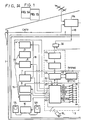
- Fig. 1 is formed of Figs. 1A and 1B drawn on two sheets of drawings so as to permit the use of a suitably large scale.
- a multi-link center 3 such as a multi-preamplifier or the like is installed within this master room 2.
- the multi-link center 3 within this master room 2 is supplied with cable TV (CATV) information and so on through a mixer 17a and cable 18.
- the audio information 16 and the video information 15 from these plurality of concentratedly installed apparatus within the master room 2 are distributed through the mixer 17a, a distributor 17b and a cable 19 to a plurality of rooms 20, 21, 22 and 23 so that these informations can be selectively viewed and listened to in these rooms by remote controllers 14a to 14c.
- the rooms 20, 21 and 22 have multi-link receivers 25, 26 and 27 provided therein, respectively.
- the multi-link receiver 25 is provided with left and right speakers 28L and 28R.
- the audio information 16 from, for example, the CD player 4 or the like can be listened to, and in the room 21 the multi-link receiver 26, left and right speakers 29L and 29R, and a TV receiver 30 are installed so that the video information 15 from, for example, the VTR 8 can be viewed by the operation of the remote controller 14b.
- the audio information 16 from, for example, the DAT 6 can be listened to through the multi-link receiver 27 and left and right speakers 30L, 30R by the operation of the remote controller 14c.
- a TV receiver 31 is installed so that CATV can be viewed thereon.
- the RF signals of CATV and so on from a two-output distributor 32 within the master room 2 are supplied to a three-output distributor 33, thereby distributed as, for example, the RF signal of the TV to the TV receiver 13 for CATV, the RF signal of FM to the tuner 7 and the RF signal of TV to the VTR 8.
- reference numeral 40 represents a frequency band of 45 MHz to 370 MHz including, for example, channels 2 to 50 of frequency-modulated (FM) CATV.
- the AV (audio visual) informations to be used in the MLS of this embodiment are located above and below the CATV band.
- the video information 15 is an analog signal which is AM and FM-modulated and located on the upper side of the CATV band
- the audio information 16 is digitized, two-phase modulated (i.e., 2PSK: phase shift keying), and located on the lower side of the CATV band.
- the audio information 16 and the video information 15 are both modulated in a frequency multiplex fashion.
- a first remote control signal 41 and a second remote control signal 42 for remote control are digitally frequency-modulated (FSK: frequency shift keying).
- the carrier frequency of the first remote control signal 41 is selected to be, for example, 16.5 MHz, and that of the second remote control signal 42 is selected to be 17.5 MHz.
- These remote control signals are modulated in a timebase multiplex fashion.
- the first remote control signal 41 is used to control from the master room 2, for example, the multi-link receivers 25, 26, 27 or the like in the respectiverooms
- the second remote control signal 42 is used for the control from the remote controllers 14a to 14c of the respective rooms to the multi-link center 3 of the master room 2.
- the remote control signal from the remote controller 14a to 14c might be a control signal of SIRCS (Sony Infrared Remote Control System) which the applicant of the present application creates and employs for the remote control of audio visual apparatus.
- SIRCS remote control signal has a format of infrared digital code system and a code format thereof is represented in Fig. 3.
- the format of one frame is normally formed of 15 bits (or 12 bits) which includes a guide pulse 36 as an identification (ID) signal for specifying the start and a binary code of 15 bits (or 12 bits) which begins at 2 degrees following this guide pulse 36.
- This binary code is formed of a data code 37 of 7 bits indicative of control function, and a merchandise code 38 of 8 bits indicative of merchandise category, following this data code 37.
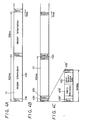
- Figs. 4A through 4C are format diagrams, respectively, of the first remote control signal 41 supplied from the multi-link center 3 to the multi-link receivers 25, 26 and 27 of the respective rooms, and the second remote control signal 42 supplied from the remote controllers 14a to 14c of the respective rooms to the multi-link center 3.
- Fig. 4A shows the format of the first remote control signal, which is formed of a synchronizing (sync.) signal 41a at the head thereof and of a next master information 41b such as data transmission room number and a transmission/reception permission flag or the like and which is repeatedly sent at every 100 ms of time.
- Fig. 4B shows the format of the second remote control signal 42, which is formed of control data 42a, 42b, ..., 42p of 1024 bits for the first room to sixteenth room, and which is repeatedly sent at every 100 ms of time.
- the data of each room as shown in Fig. 4C is formed of a sync.
- the second remote control signal 42 from the remote controllers 14a to 14c and which is distributed by the two-output distributor 32 within the master room 2 has a carrier of 17.5 MHz and undergoes RF processing in an RF circuit 43.
- the thus processed signal is then supplied to the following first decoder 44, in which data of certain bits of the second 100-ms remote control signal 42 shown in Fig. 4B is decoded and from which decoded data is derived.
- the decoded signal is supplied to the following second decoder 45, which then produces data of 64 bits of one room unit as shown in Fig. 4C.
- the output of the second decoder 45 is supplied to a microcomputer (hereinafter referred to as a CPU (central processing unit)) 47.
- a CPU central processing unit
- This CPU 47 is capable of simultaneously processing remote control signals 100-ms interval data of 16 rooms, and has a memory 46. This CPU 47 also arranges data read from the remote control signal of 64 bits at each room. If the CD player 4 and DAT 6 are found to be in the playback mode from the command state from the remote control signals 14a to 14c, then the CPU 47 raises flags on the table corresponding to the CD player 4 and the DAT 6 in the memory 46 and supplies control data with the flags raised, from parallel output terminals 49 of the CPU 47 to the CD player 4, the DAT 6 the tuner 7, the VTR 8, the main amplifier 10 and so on within 100 ms.
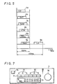
- This control data is the SIRCS signal of 45 ms per frame earlier noted with reference to Fig. 3.
- control data of two frames used to process one command are supplied to a plurality of electronic apparatus such as the CD player 4, the DAT 6, the tuner 7, the VTR 8, the main amplifier 10 or the like in parallel substantially simultaneously so that control data can be supplied to the plurality of electronic apparatus during 100 ms of time, as shown in Fig. 5.
- the CPU 47 in this embodiment is provided with a series output terminal 50 for SIRCS from which the remote control signal is derived because the control data cannot be supplied from the SIRCS control data output terminals 49.
- control data light-modulated is transmitted through the output terminal 50 from a light emitting element 51a, thus enabling the control data to be supplied to the deck 5 and the laser disc player 9 having no SIRCS terminal.
- the controlling time of 200 ms is required, but the waiting time upon operation can be reduced by selecting two modes at a time.
- a switch group 35 by which the series or parallel state can be selected is provided on the CPU 47, and the electronic apparatus which is desired to be controlled in series is made in ground potential by closing its corresponding switch so that the control data can be delivered in series. Also, although in Fig. 1 it is not shown that the AV informations are delivered from the electronic apparatus 4 to 9, these informations are supplied in parallel from these apparatus 4 to 9 to the multi-link center 3.
- control data is supplied to the deck 5 and the laser disc player 9 having no SIRCS terminal from the common light emitting device 51a as described above, if for the apparatus having no SIRCS terminal there are provided exclusive light emitting elements respectively, the controlling time can be reduced more.
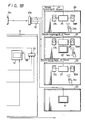
- Fig. 6 shows a second embodiment of the present invention in which the controlling time can be reduced more.
- Fig. 6 is formed of Figs. 6A and 6B drawn on two sheets of drawings so as to permit the use of a suitably large scale and in Fig. 6, like parts corresponding to those of Fig. 1 are marked with the same references and therefore need not be described in detail.
- the multi-link center 3 includes a conversion table 48 formed of a rewritable memory for the apparatus which cannot be operated by the SIRCS signal.
- the SIRCS signal is supplied to the conversion table 48, in which it is converted into control data stored therein by the operation which will be later referred to, and the thus converted control data is supplied to the corresponding apparatus.
- control data produced separately for the respective apparatus from the CPU 47 are switched by change-over switches 51 to 57 to be distributed to the path including the conversion table 48 and to the path not including the conversion table 48. Then, the output from the conversion table 48 and the control data directly supplied from the switches 51 to 57 are switched to respective single signal lines by change-over switches 61 to 67 and then transmitted through the parallel output terminals 49 to the respective apparatus as control data.
- the change-over switches 51 to 57 and the change-over switches 61 to 67 are operated in unison with each other under the control of the CPU 47, so that the change-over switches associated with the apparatus which have made operation of storing the control data are changed to the conversion table 48 side position.
- the CD player 4, the DAT 6, the tuner 7, the VTR 8 and the main amplifier 10 are the apparatus of the same maker which can be operated by the SIRCS signal and that the deck 5 and the laser disc player 9 are the apparatus of different makers which have no SIRCS terminals and which can be operated by the remote control signal of control codes different from the SIRCS signal.
- the apparatus 4, 6, 7, 8, 10 which can be operated by the SIRCS signals are directly supplied at their SIRCS signal input terminals with the control signals (SIRCS signals) produced through the parallel output terminals 49.
- the control signals produced from the parallel output terminals 49 are supplied to infrared signal light emitting units 5a, 9a which are respectively opposite the respective infrared remote control signal receiving portions of the apparatus 5, 9 and the infrared signal light emitting units 5a, 9a supply infrared signals as control data to the signal receiving portions of the apparatus.
- Fig. 7 shows one example of the front panel of the multi-link center 3.
- the mode change-over switch 74 is first operated to select an operation mode of the multi-link center 3 as a learning mode. At this time, the pilot lamps 72 associated with the function by which the control codes other than the SIRCS signals are already stored in the conversion table 48 are lit, and the pilot lamps 72 associated with the function by which the control codes other than the SIRCS signal are not stored are intermittently lit.
- the control data for the deck 5 and for the laser disc player 9 must be input.
- the user pushes the function change-over switch 71 associated with the deck 5.
- the pilot lamp 72 associated with the deck 5 blinks.
- the user brings the remote controller (not shown) attached to the deck 5 and which derives a remote control signal other than the SIRCS signal close to the remote control signal receiving portion 75 and pushes the operation key of the same function of the remote controller, so that the remote controller of the deck 5 emits the corresponding remote control signal to the remote control signal receiving portion 75.
- the remote control signal received by the remote control signal receiving portion 75 is stored in the corresponding address of the conversion table 48 under the control of the CPU 47.
- the blinking pilot lamp 72 is continuously turned on.
- the pilot lamp 72 is again blinked.
- the function change-over switch 71 associated with the laser disc player 9 is pushed and then the operation key 73 and the remote controller of the laser disc player 9 are operated. After the completion of the control data storing operation, the mode change-over switch 74 is operated to bring the operation mode of the multi-link center 3 back to the normal mode.
- the control codes to be supplied from the CPU 47 to the apparatus are controlled by the switching operation of the change-over switches 51 to 57 and change-over switches 61 to 67 so as to be fed through the conversion table 48 to the parallel output terminals 49.
- the SIRCS signal is supplied to the conversion table 48, the stored control data of other codes of the same function is read from the conversion table 48, and supplied through the parallel output terminals 49.
- control data of SIRCS signal is generated from the remote controller 14 within the master room 2
- control data of SIRCS signal are generated from the remote controllers 14a to 14c within the respective rooms 20, 21, 22, 23 and fed through the above-mentioned transmission paths to the multi-link center 3
- the control data of SIRCS signal are directly supplied to the apparatus (the CD player 4, the DAT 6, the tuner 7, the VTR 8 and the main amplifier 10) which can be operated by the SIRCS signal
- the corresponding control data read from the conversion table 48 are fed to the apparatus (the deck 5 and the laser disc player 9) which can be operated by other control codes, so that the respective apparatus can be controlled by the MLS irrespective of the kinds of the control codes.
- the control signal can be processed during a reduced time. Furthermore, even when the apparatus operable by the remote control signal of control code other than the SIRCS signal is installed within the master room, such remote control signal is converted into a remote control signal associated with the apparatus, thus making it possible to control apparatus having different control codes.
Landscapes
- Engineering & Computer Science (AREA)
- Computer Networks & Wireless Communication (AREA)
- Signal Processing (AREA)
- Selective Calling Equipment (AREA)
Applications Claiming Priority (4)
| Application Number | Priority Date | Filing Date | Title |
|---|---|---|---|
| JP113268/90 | 1990-04-28 | ||
| JP2113268A JP2830362B2 (ja) | 1990-04-28 | 1990-04-28 | 送受信装置 |
| JP144888/90 | 1990-06-01 | ||
| JP2144888A JPH0437394A (ja) | 1990-06-01 | 1990-06-01 | 信号処理装置 |
Publications (3)
| Publication Number | Publication Date |
|---|---|
| EP0455549A2 true EP0455549A2 (fr) | 1991-11-06 |
| EP0455549A3 EP0455549A3 (en) | 1992-09-16 |
| EP0455549B1 EP0455549B1 (fr) | 1998-08-19 |
Family
ID=26452261
Family Applications (1)
| Application Number | Title | Priority Date | Filing Date |
|---|---|---|---|
| EP91401126A Expired - Lifetime EP0455549B1 (fr) | 1990-04-28 | 1991-04-26 | Système de transmission de signaux pour télécommander des appareils électroniques |
Country Status (4)
| Country | Link |
|---|---|
| US (1) | US5321846A (fr) |
| EP (1) | EP0455549B1 (fr) |
| KR (1) | KR100246281B1 (fr) |
| DE (1) | DE69130001T2 (fr) |
Cited By (1)
| Publication number | Priority date | Publication date | Assignee | Title |
|---|---|---|---|---|
| US5321846A (en) * | 1990-04-28 | 1994-06-14 | Sony Corporation | Signal transmission system with quicker response and with parallel and serial outputs |
Families Citing this family (103)
| Publication number | Priority date | Publication date | Assignee | Title |
|---|---|---|---|---|
| US5666136A (en) * | 1991-12-17 | 1997-09-09 | Sony Corporation | Audio equipment and method of displaying operation thereof |
| US6067072A (en) * | 1991-12-17 | 2000-05-23 | Sony Corporation | Audio equipment and method of displaying operating thereof |
| US5631850A (en) * | 1992-09-11 | 1997-05-20 | Sony Corporation | Audio visual equipment with a digital bus system and method for initializing and confirming connection |
| CA2271555C (fr) | 1992-12-09 | 2003-11-11 | Discovery Communications, Inc. | Commande a distance pour systeme de television cable |
| US7336788B1 (en) | 1992-12-09 | 2008-02-26 | Discovery Communicatoins Inc. | Electronic book secure communication with home subsystem |
| US7849393B1 (en) | 1992-12-09 | 2010-12-07 | Discovery Communications, Inc. | Electronic book connection to world watch live |
| US7509270B1 (en) | 1992-12-09 | 2009-03-24 | Discovery Communications, Inc. | Electronic Book having electronic commerce features |
| US8073695B1 (en) | 1992-12-09 | 2011-12-06 | Adrea, LLC | Electronic book with voice emulation features |
| US7835989B1 (en) | 1992-12-09 | 2010-11-16 | Discovery Communications, Inc. | Electronic book alternative delivery systems |
| US7401286B1 (en) | 1993-12-02 | 2008-07-15 | Discovery Communications, Inc. | Electronic book electronic links |
| JPH06217250A (ja) * | 1993-01-20 | 1994-08-05 | Sony Corp | Av機器の信号ラインの制御方法 |
| US20020048448A1 (en) * | 1993-03-29 | 2002-04-25 | Microsoft Corporation | Pausing the display of a television program as a signal including the television program is received |
| US8046800B2 (en) * | 1993-03-29 | 2011-10-25 | Microsoft Corporation | Remotely controlling a video recorder |
| US7865567B1 (en) | 1993-12-02 | 2011-01-04 | Discovery Patent Holdings, Llc | Virtual on-demand electronic book |
| US8095949B1 (en) | 1993-12-02 | 2012-01-10 | Adrea, LLC | Electronic book with restricted access features |
| US7861166B1 (en) | 1993-12-02 | 2010-12-28 | Discovery Patent Holding, Llc | Resizing document pages to fit available hardware screens |
| US9053640B1 (en) | 1993-12-02 | 2015-06-09 | Adrea, LLC | Interactive electronic book |
| US8661477B2 (en) | 1994-10-12 | 2014-02-25 | Touchtunes Music Corporation | System for distributing and selecting audio and video information and method implemented by said system |
| US7188352B2 (en) | 1995-07-11 | 2007-03-06 | Touchtunes Music Corporation | Intelligent digital audiovisual playback system |
| US7424731B1 (en) | 1994-10-12 | 2008-09-09 | Touchtunes Music Corporation | Home digital audiovisual information recording and playback system |
| WO1996012255A1 (fr) | 1994-10-12 | 1996-04-25 | Technical Maintenance Corporation | Systeme de reproduction audio-visuelle numerique intelligent |
| TW250616B (en) | 1994-11-07 | 1995-07-01 | Discovery Communicat Inc | Electronic book selection and delivery system |
| US5710712A (en) * | 1994-11-22 | 1998-01-20 | Motorola, Inc. | Processor system and method for appliances |
| US7917922B1 (en) | 1995-06-08 | 2011-03-29 | Schwab Barry H | Video input switching and signal processing apparatus |
| FR2736787B1 (fr) * | 1995-07-11 | 1997-08-08 | Alcatel Business Systems | Systeme de communication et equipements correspondants pour installation d'abonne |
| US6177963B1 (en) | 1996-04-22 | 2001-01-23 | Multiplex Technology, Inc. | Video signal distribution system |
| FR2753868A1 (fr) | 1996-09-25 | 1998-03-27 | Technical Maintenance Corp | Procede de selection d'un enregistrement sur un systeme numerique de reproduction audiovisuel et systeme pour mise en oeuvre du procede |
| JP3658896B2 (ja) * | 1996-11-26 | 2005-06-08 | ソニー株式会社 | 情報信号伝送システム、再生装置及び表示装置 |
| US20030192053A1 (en) * | 1997-02-19 | 2003-10-09 | Next Level Communications, Inc. | Method and apparatus for transmitting wireless signals over media |
| US20040083493A1 (en) * | 1997-02-19 | 2004-04-29 | Next Level Communications, Inc. | Transmitting caller ID within a digital stream |
| US5936667A (en) * | 1997-05-13 | 1999-08-10 | Sony Corporation | System and method for testing and updating stored content of a remote transmitter for an entertainment system |
| FR2769165B1 (fr) | 1997-09-26 | 2002-11-29 | Technical Maintenance Corp | Systeme sans fil a transmission numerique pour haut-parleurs |
| US20030035556A1 (en) * | 1997-11-18 | 2003-02-20 | Jerry Curtis | Audio distribution system |
| FR2781582B1 (fr) | 1998-07-21 | 2001-01-12 | Technical Maintenance Corp | Systeme de telechargement d'objets ou de fichiers pour mise a jour de logiciels |
| FR2781593B1 (fr) * | 1998-07-22 | 2001-01-12 | Technical Maintenance Corp | Telecommande pour systeme de reproduction audiovisuelle numerique intelligent |
| FR2781580B1 (fr) | 1998-07-22 | 2000-09-22 | Technical Maintenance Corp | Circuit de commande de son pour systeme de reproduction audiovisuelle numerique intelligent |
| US8028318B2 (en) | 1999-07-21 | 2011-09-27 | Touchtunes Music Corporation | Remote control unit for activating and deactivating means for payment and for displaying payment status |
| FR2781591B1 (fr) | 1998-07-22 | 2000-09-22 | Technical Maintenance Corp | Systeme de reproduction audiovisuelle |
| US6189148B1 (en) * | 1999-01-28 | 2001-02-13 | Douglas G. Brown | Methods and circuits using frequency shift keying modulation to transfer data over transmission lines simultaneous with television signals |
| US8726330B2 (en) | 1999-02-22 | 2014-05-13 | Touchtunes Music Corporation | Intelligent digital audiovisual playback system |
| US8266657B2 (en) * | 2001-03-15 | 2012-09-11 | Sling Media Inc. | Method for effectively implementing a multi-room television system |
| US6263503B1 (en) * | 1999-05-26 | 2001-07-17 | Neal Margulis | Method for effectively implementing a wireless television system |
| FR2796482B1 (fr) | 1999-07-16 | 2002-09-06 | Touchtunes Music Corp | Systeme de gestion a distance d'au moins un dispositif de reproduction d'informations audiovisuelles |
| US6526581B1 (en) * | 1999-08-03 | 2003-02-25 | Ucentric Holdings, Llc | Multi-service in-home network with an open interface |
| FR2805377B1 (fr) | 2000-02-23 | 2003-09-12 | Touchtunes Music Corp | Procede de commande anticipee d'une selection, systeme numerique et juke-box permettant la mise en oeuvre du procede |
| FR2805060B1 (fr) | 2000-02-16 | 2005-04-08 | Touchtunes Music Corp | Procede de reception de fichiers lors d'un telechargement |
| FR2805072B1 (fr) | 2000-02-16 | 2002-04-05 | Touchtunes Music Corp | Procede d'ajustement du volume sonore d'un enregistrement sonore numerique |
| US6842459B1 (en) | 2000-04-19 | 2005-01-11 | Serconet Ltd. | Network combining wired and non-wired segments |
| FR2808906B1 (fr) | 2000-05-10 | 2005-02-11 | Touchtunes Music Corp | Dispositif et procede de gestion a distance d'un reseau de systemes de reproduction d'informations audiovisuelles |
| FR2811175B1 (fr) | 2000-06-29 | 2002-12-27 | Touchtunes Music Corp | Procede de distribution d'informations audiovisuelles et systeme de distribution d'informations audiovisuelles |
| FR2811114B1 (fr) | 2000-06-29 | 2002-12-27 | Touchtunes Music Corp | Dispositif et procede de communication entre un systeme de reproduction d'informations audiovisuelles et d'une machine electronique de divertissement |
| FR2814085B1 (fr) | 2000-09-15 | 2005-02-11 | Touchtunes Music Corp | Procede de divertissement base sur les jeux concours a choix multiples |
| US7690017B2 (en) * | 2001-05-03 | 2010-03-30 | Mitsubishi Digital Electronics America, Inc. | Control system and user interface for network of input devices |
| US20090031419A1 (en) | 2001-05-24 | 2009-01-29 | Indra Laksono | Multimedia system and server and methods for use therewith |
| US8291457B2 (en) | 2001-05-24 | 2012-10-16 | Vixs Systems, Inc. | Channel selection in a multimedia system |
| US7107608B2 (en) * | 2001-10-01 | 2006-09-12 | Microsoft Corporation | Remote task scheduling for a set top box |
| IL161190A0 (en) | 2001-10-11 | 2004-08-31 | Serconet Ltd | Outlet with analog signal adapter, method for use thereof and a network using said outlet |
| KR100454385B1 (ko) | 2002-02-25 | 2004-11-05 | 이용구 | 화장용 파우더가 내장되는 화장용구 |
| US9646339B2 (en) | 2002-09-16 | 2017-05-09 | Touchtunes Music Corporation | Digital downloading jukebox system with central and local music servers |
| US8332895B2 (en) | 2002-09-16 | 2012-12-11 | Touchtunes Music Corporation | Digital downloading jukebox system with user-tailored music management, communications, and other tools |
| US8103589B2 (en) | 2002-09-16 | 2012-01-24 | Touchtunes Music Corporation | Digital downloading jukebox system with central and local music servers |
| US12100258B2 (en) | 2002-09-16 | 2024-09-24 | Touchtunes Music Company, Llc | Digital downloading jukebox with enhanced communication features |
| US7822687B2 (en) | 2002-09-16 | 2010-10-26 | Francois Brillon | Jukebox with customizable avatar |
| US11029823B2 (en) | 2002-09-16 | 2021-06-08 | Touchtunes Music Corporation | Jukebox with customizable avatar |
| US8584175B2 (en) | 2002-09-16 | 2013-11-12 | Touchtunes Music Corporation | Digital downloading jukebox system with user-tailored music management, communications, and other tools |
| US10373420B2 (en) | 2002-09-16 | 2019-08-06 | Touchtunes Music Corporation | Digital downloading jukebox with enhanced communication features |
| US8151304B2 (en) | 2002-09-16 | 2012-04-03 | Touchtunes Music Corporation | Digital downloading jukebox system with user-tailored music management, communications, and other tools |
| IL152824A (en) | 2002-11-13 | 2012-05-31 | Mosaid Technologies Inc | A socket that can be connected to and the network that uses it |
| IL157787A (en) * | 2003-09-07 | 2010-12-30 | Mosaid Technologies Inc | Modular outlet for data communications network |
| IL159838A0 (en) | 2004-01-13 | 2004-06-20 | Yehuda Binder | Information device |
| IL160417A (en) * | 2004-02-16 | 2011-04-28 | Mosaid Technologies Inc | Unit added to the outlet |
| IL161869A (en) | 2004-05-06 | 2014-05-28 | Serconet Ltd | A system and method for carrying a signal originating is wired using wires |
| US7769756B2 (en) * | 2004-06-07 | 2010-08-03 | Sling Media, Inc. | Selection and presentation of context-relevant supplemental content and advertising |
| US9998802B2 (en) * | 2004-06-07 | 2018-06-12 | Sling Media LLC | Systems and methods for creating variable length clips from a media stream |
| US8099755B2 (en) * | 2004-06-07 | 2012-01-17 | Sling Media Pvt. Ltd. | Systems and methods for controlling the encoding of a media stream |
| US7975062B2 (en) * | 2004-06-07 | 2011-07-05 | Sling Media, Inc. | Capturing and sharing media content |
| US8346605B2 (en) * | 2004-06-07 | 2013-01-01 | Sling Media, Inc. | Management of shared media content |
| US7917932B2 (en) * | 2005-06-07 | 2011-03-29 | Sling Media, Inc. | Personal video recorder functionality for placeshifting systems |
| US7647614B2 (en) | 2004-06-07 | 2010-01-12 | Sling Media, Inc. | Fast-start streaming and buffering of streaming content for personal media player |
| JP3824004B2 (ja) * | 2005-03-03 | 2006-09-20 | オンキヨー株式会社 | 指令変換装置 |
| US7813451B2 (en) * | 2006-01-11 | 2010-10-12 | Mobileaccess Networks Ltd. | Apparatus and method for frequency shifting of a wireless signal and systems using frequency shifting |
| US12450978B2 (en) | 2007-01-17 | 2025-10-21 | Touchtunes Music Company Llc. | Coin operated entertainment system |
| US9330529B2 (en) | 2007-01-17 | 2016-05-03 | Touchtunes Music Corporation | Game terminal configured for interaction with jukebox device systems including same, and/or associated methods |
| US9171419B2 (en) | 2007-01-17 | 2015-10-27 | Touchtunes Music Corporation | Coin operated entertainment system |
| US9953481B2 (en) | 2007-03-26 | 2018-04-24 | Touchtunes Music Corporation | Jukebox with associated video server |
| US8332887B2 (en) | 2008-01-10 | 2012-12-11 | Touchtunes Music Corporation | System and/or methods for distributing advertisements from a central advertisement network to a peripheral device via a local advertisement server |
| US10290006B2 (en) | 2008-08-15 | 2019-05-14 | Touchtunes Music Corporation | Digital signage and gaming services to comply with federal and state alcohol and beverage laws and regulations |
| WO2009053910A2 (fr) | 2007-10-22 | 2009-04-30 | Mobileaccess Networks Ltd. | Système de communication utilisant des fils à faible bande passante |
| US8175649B2 (en) | 2008-06-20 | 2012-05-08 | Corning Mobileaccess Ltd | Method and system for real time control of an active antenna over a distributed antenna system |
| WO2010005569A1 (fr) | 2008-07-09 | 2010-01-14 | Touchtunes Music Corporation | Jukebox de téléchargement numérique à caractéristiques d'amélioration des recettes |
| WO2010089719A1 (fr) | 2009-02-08 | 2010-08-12 | Mobileaccess Networks Ltd. | Système de communication utilisant des câbles transportant des signaux ethernet |
| US10719149B2 (en) | 2009-03-18 | 2020-07-21 | Touchtunes Music Corporation | Digital jukebox device with improved user interfaces, and associated methods |
| US10564804B2 (en) | 2009-03-18 | 2020-02-18 | Touchtunes Music Corporation | Digital jukebox device with improved user interfaces, and associated methods |
| US12112093B2 (en) | 2009-03-18 | 2024-10-08 | Touchtunes Music Company, Llc | Entertainment server and associated social networking services |
| US9292166B2 (en) | 2009-03-18 | 2016-03-22 | Touchtunes Music Corporation | Digital jukebox device with improved karaoke-related user interfaces, and associated methods |
| EP2409273A4 (fr) | 2009-03-18 | 2016-05-11 | Touchtunes Music Corp | Serveur de divertissement et services de réseau social associés |
| CN105374380A (zh) | 2010-01-26 | 2016-03-02 | 踏途音乐公司 | 具有改进的用户界面的数字点播设备和相关方法 |
| GB2526955B (en) | 2011-09-18 | 2016-06-15 | Touchtunes Music Corp | Digital jukebox device with karaoke and/or photo booth features, and associated methods |
| US11151224B2 (en) | 2012-01-09 | 2021-10-19 | Touchtunes Music Corporation | Systems and/or methods for monitoring audio inputs to jukebox devices |
| WO2013142662A2 (fr) | 2012-03-23 | 2013-09-26 | Corning Mobile Access Ltd. | Puce(s) de circuit intégré à radiofréquence (rfic) servant à fournir des fonctionnalités de système d'antenne à répartition, et composants, systèmes, et procédés connexes |
| WO2015070070A1 (fr) | 2013-11-07 | 2015-05-14 | Touchtunes Music Corporation | Techniques de création de dispositions d'une interface utilisateur graphique d'un menu électronique destinées à être utilisées en association avec des dispositifs électroniques |
| CA2943616A1 (fr) | 2014-03-25 | 2015-10-01 | Touchtunes Music Corporation | Dispositif de juke-box numerique ayant des interfaces utilisateurs ameliorees, et procedes associes |
| US9184960B1 (en) | 2014-09-25 | 2015-11-10 | Corning Optical Communications Wireless Ltd | Frequency shifting a communications signal(s) in a multi-frequency distributed antenna system (DAS) to avoid or reduce frequency interference |
Family Cites Families (9)
| Publication number | Priority date | Publication date | Assignee | Title |
|---|---|---|---|---|
| JPS562789A (en) * | 1979-06-21 | 1981-01-13 | Pioneer Electronic Corp | Line remote monitor method in catv system |
| US4381522A (en) * | 1980-12-01 | 1983-04-26 | Adams-Russell Co., Inc. | Selective viewing |
| US4769833A (en) * | 1986-03-31 | 1988-09-06 | American Telephone And Telegraph Company | Wideband switching system |
| JPH07105895B2 (ja) * | 1986-06-02 | 1995-11-13 | ソニー株式会社 | 電子機器 |
| JP2722450B2 (ja) * | 1987-02-25 | 1998-03-04 | ソニー株式会社 | 集中管理装置 |
| US4885803A (en) * | 1987-03-17 | 1989-12-05 | Lawrence W. Hermann | System and method for controlling a plurality of electronic entertainment devices |
| JPS647791A (en) * | 1987-06-30 | 1989-01-11 | Nec Corp | Multiscreen video conference method and device therefor |
| JP2976434B2 (ja) * | 1989-02-28 | 1999-11-10 | ソニー株式会社 | 制御信号伝送システム |
| US5321846A (en) * | 1990-04-28 | 1994-06-14 | Sony Corporation | Signal transmission system with quicker response and with parallel and serial outputs |
-
1991
- 1991-04-19 US US07/687,749 patent/US5321846A/en not_active Expired - Lifetime
- 1991-04-26 EP EP91401126A patent/EP0455549B1/fr not_active Expired - Lifetime
- 1991-04-26 DE DE69130001T patent/DE69130001T2/de not_active Expired - Lifetime
- 1991-04-26 KR KR1019910006739A patent/KR100246281B1/ko not_active Expired - Lifetime
Cited By (1)
| Publication number | Priority date | Publication date | Assignee | Title |
|---|---|---|---|---|
| US5321846A (en) * | 1990-04-28 | 1994-06-14 | Sony Corporation | Signal transmission system with quicker response and with parallel and serial outputs |
Also Published As
| Publication number | Publication date |
|---|---|
| US5321846A (en) | 1994-06-14 |
| DE69130001D1 (de) | 1998-09-24 |
| DE69130001T2 (de) | 1999-04-01 |
| KR100246281B1 (ko) | 2000-03-15 |
| EP0455549A3 (en) | 1992-09-16 |
| EP0455549B1 (fr) | 1998-08-19 |
Similar Documents
| Publication | Publication Date | Title |
|---|---|---|
| US5321846A (en) | Signal transmission system with quicker response and with parallel and serial outputs | |
| US5193208A (en) | Signal transmission system | |
| EP0124331B2 (fr) | Dispositif émetteur de télécommande d'un ou plusieurs appareils de télévision | |
| US5341166A (en) | System for controlling selected devices having unique sets of control codes | |
| US5255180A (en) | Control apparatus for systematically operating audio and/or video sets | |
| US5828417A (en) | Television receiver with on screen display for reserving programs to be recorded or viewed | |
| US5959539A (en) | Apparatus for the remote control of electronic devices with key allocation | |
| US4771283A (en) | Remote control device | |
| US7821377B2 (en) | Remote controller, equipment operation system, and remote control method | |
| HU207918B (en) | Remote control control system | |
| CN1073820A (zh) | 盒带录像机电缆转换器单元的开/关控制 | |
| US20050151886A1 (en) | Remote controller | |
| GB2193608A (en) | Video source selecting systems | |
| CN1075838A (zh) | 耦合到盒式磁带录相机电缆转换器单元的自动检测 | |
| KR100201447B1 (ko) | 신호전송장치 | |
| JP2687392B2 (ja) | リモートコントロール装置 | |
| JPS6375805A (ja) | 遠隔操作装置 | |
| JP2830362B2 (ja) | 送受信装置 | |
| JPH0652664A (ja) | 制御装置 | |
| JPH0437394A (ja) | 信号処理装置 | |
| JP2913771B2 (ja) | 伝送装置 | |
| JPH0410279B2 (fr) | ||
| JP2913772B2 (ja) | ホームバスシステム、受信装置及び送信装置 | |
| JP2886395B2 (ja) | ホームターミナル | |
| CA2108054C (fr) | Dispositif de commande audio-visuel afin de determiner la connexion aux appareils et des commandes de fonctions des appareils |
Legal Events
| Date | Code | Title | Description |
|---|---|---|---|
| PUAI | Public reference made under article 153(3) epc to a published international application that has entered the european phase |
Free format text: ORIGINAL CODE: 0009012 |
|
| AK | Designated contracting states |
Kind code of ref document: A2 Designated state(s): DE FR GB IT |
|
| PUAL | Search report despatched |
Free format text: ORIGINAL CODE: 0009013 |
|
| AK | Designated contracting states |
Kind code of ref document: A3 Designated state(s): DE FR GB IT |
|
| 17P | Request for examination filed |
Effective date: 19930304 |
|
| 17Q | First examination report despatched |
Effective date: 19951221 |
|
| GRAG | Despatch of communication of intention to grant |
Free format text: ORIGINAL CODE: EPIDOS AGRA |
|
| GRAG | Despatch of communication of intention to grant |
Free format text: ORIGINAL CODE: EPIDOS AGRA |
|
| GRAH | Despatch of communication of intention to grant a patent |
Free format text: ORIGINAL CODE: EPIDOS IGRA |
|
| GRAH | Despatch of communication of intention to grant a patent |
Free format text: ORIGINAL CODE: EPIDOS IGRA |
|
| GRAA | (expected) grant |
Free format text: ORIGINAL CODE: 0009210 |
|
| AK | Designated contracting states |
Kind code of ref document: B1 Designated state(s): DE FR GB IT |
|
| REF | Corresponds to: |
Ref document number: 69130001 Country of ref document: DE Date of ref document: 19980924 |
|
| ET | Fr: translation filed | ||
| PLBQ | Unpublished change to opponent data |
Free format text: ORIGINAL CODE: EPIDOS OPPO |
|
| PLBI | Opposition filed |
Free format text: ORIGINAL CODE: 0009260 |
|
| PLAB | Opposition data, opponent's data or that of the opponent's representative modified |
Free format text: ORIGINAL CODE: 0009299OPPO |
|
| PLBF | Reply of patent proprietor to notice(s) of opposition |
Free format text: ORIGINAL CODE: EPIDOS OBSO |
|
| 26 | Opposition filed |
Opponent name: INTERESSENGEMEINSCHAFT FUER RUNDFUNKSCHUTZRECHTE E Effective date: 19990518 |
|
| R26 | Opposition filed (corrected) |
Opponent name: INTERESSENGEMEINSCHAFT FUER RUNDFUNKSCHUTZRECHTE G Effective date: 19990518 |
|
| PLBF | Reply of patent proprietor to notice(s) of opposition |
Free format text: ORIGINAL CODE: EPIDOS OBSO |
|
| PLBF | Reply of patent proprietor to notice(s) of opposition |
Free format text: ORIGINAL CODE: EPIDOS OBSO |
|
| PLBO | Opposition rejected |
Free format text: ORIGINAL CODE: EPIDOS REJO |
|
| PLBN | Opposition rejected |
Free format text: ORIGINAL CODE: 0009273 |
|
| STAA | Information on the status of an ep patent application or granted ep patent |
Free format text: STATUS: OPPOSITION REJECTED |
|
| REG | Reference to a national code |
Ref country code: GB Ref legal event code: IF02 |
|
| 27O | Opposition rejected |
Effective date: 20010713 |
|
| REG | Reference to a national code |
Ref country code: GB Ref legal event code: 746 Effective date: 20091124 |
|
| PGFP | Annual fee paid to national office [announced via postgrant information from national office to epo] |
Ref country code: GB Payment date: 20100331 Year of fee payment: 20 |
|
| PGFP | Annual fee paid to national office [announced via postgrant information from national office to epo] |
Ref country code: FR Payment date: 20100506 Year of fee payment: 20 |
|
| PGFP | Annual fee paid to national office [announced via postgrant information from national office to epo] |
Ref country code: DE Payment date: 20100423 Year of fee payment: 20 Ref country code: IT Payment date: 20100426 Year of fee payment: 20 |
|
| REG | Reference to a national code |
Ref country code: DE Ref legal event code: R071 Ref document number: 69130001 Country of ref document: DE |
|
| REG | Reference to a national code |
Ref country code: GB Ref legal event code: PE20 Expiry date: 20110425 |
|
| PG25 | Lapsed in a contracting state [announced via postgrant information from national office to epo] |
Ref country code: GB Free format text: LAPSE BECAUSE OF EXPIRATION OF PROTECTION Effective date: 20110425 |
|
| PG25 | Lapsed in a contracting state [announced via postgrant information from national office to epo] |
Ref country code: DE Free format text: LAPSE BECAUSE OF EXPIRATION OF PROTECTION Effective date: 20110426 |