EP0455552A1 - Betätigungsvorrichtung für Ausgabeventil - Google Patents
Betätigungsvorrichtung für Ausgabeventil Download PDFInfo
- Publication number
- EP0455552A1 EP0455552A1 EP91401134A EP91401134A EP0455552A1 EP 0455552 A1 EP0455552 A1 EP 0455552A1 EP 91401134 A EP91401134 A EP 91401134A EP 91401134 A EP91401134 A EP 91401134A EP 0455552 A1 EP0455552 A1 EP 0455552A1
- Authority
- EP
- European Patent Office
- Prior art keywords
- container
- ring
- valve
- longitudinal axis
- support
- Prior art date
- Legal status (The legal status is an assumption and is not a legal conclusion. Google has not performed a legal analysis and makes no representation as to the accuracy of the status listed.)
- Granted
Links
Images

Classifications
-
- B—PERFORMING OPERATIONS; TRANSPORTING
- B65—CONVEYING; PACKING; STORING; HANDLING THIN OR FILAMENTARY MATERIAL
- B65D—CONTAINERS FOR STORAGE OR TRANSPORT OF ARTICLES OR MATERIALS, e.g. BAGS, BARRELS, BOTTLES, BOXES, CANS, CARTONS, CRATES, DRUMS, JARS, TANKS, HOPPERS, FORWARDING CONTAINERS; ACCESSORIES, CLOSURES, OR FITTINGS THEREFOR; PACKAGING ELEMENTS; PACKAGES
- B65D83/00—Containers or packages with special means for dispensing contents
- B65D83/14—Containers for dispensing liquid or semi-liquid contents by internal gaseous pressure, i.e. aerosol containers comprising propellant
- B65D83/16—Actuating means
- B65D83/20—Actuator caps
Definitions
- the present invention relates to a device for actuating a dispensing valve fitted to a container, containing a product to be dispensed, in particular a pressurized aerosol, the valve comprising a tubular push control rod.
- FR-A-2 113 376 describes an actuating device for regulating the distribution of a material, from a pressurized container provided with an upper opening formed by a bowl for mounting a valve, the bowl being fixed to the container opening by a crimping bead or rolled seal.
- This device comprises a lever in one piece provided at one end with a surface which can be engaged by an operator's finger and at the other end with a flexible clip which clips onto the bead. Between these two ends, the lever comprises a stud coming into abutment against the end of the tubular control rod of the valve.
- the clip and the corresponding bead part constitute the fulcrum of the lever.
- the lever pivots substantially around an axis orthogonal to the longitudinal axis defined by the tubular rod.
- This construction has drawbacks.
- the area of application of the force has a small angular extent and it is advisable to apply a finger to the area provided for this purpose which is of modest size.
- the lever multiplier effect of the lever is limited by the very construction of the device, since the fulcrum of the lever is located approximately on the bead of the closure cup of the container while the other end preferably does not exceed the overall radial of the container for reasons of space and also to allow the establishment of a cover covering the entire device and coming to be fixed on the container.
- the force to be exerted must be applied to an angularly reduced area and, moreover, it remains significant since the leverage is limited by the very construction of the device.
- GB-A-1 359 152 describes a device in which the area of application of force by the user has an angular extent of 360 °, which allows the user to have a large bearing surface and choose without constraint the point where the actuation force will be exerted.
- the push button is constituted by a conical surface comprising on its axis a stud, which presses on the valve stem, a cylindrical skirt being integral with said conical surface and being provided with support means capable of cooperating , either outside or inside, with a stop constituted by the crimping bead of the valve bowl.
- a lever system is formed, the fulcrum of which is located on the crimping bead, this fulcrum being located substantially in a plane passing through the longitudinal axis and the point of application of the force.
- the lever multiplying effect of the lever is determined by the construction of the container and, consequently, the force to be applied necessarily remains significant.
- the present invention relates to a device in which the force to be applied by the user to depress the valve stem can be modularly reduced, without modifying the force of the valve spring.
- the present invention consists of a device for actuating a dispensing valve fitted to a container containing a product to be dispensed, in particular a pressurized aerosol, the valve comprising a tubular control rod defining a longitudinal axis and having an end provided a dispensing orifice, the device comprising lever means for actuating the valve, these means comprising a push button, the external face of which comprises an application zone for an actuating force of the valve, the push button comprising, on the one hand, a stud abutting against the end of the rod and equipped with a dispensing nozzle and a channel connecting the dispensing orifice to said nozzle and, on the other hand, means of '' own support to cooperate with complementary abutment means linked to the container to form a fulcrum of the lever, in which said zone of application has an angular extent centered s ur said longitudinal axis of at least about 180 ° and, the support means and the abutment means have
- the support points of the lever on the ring are preferably located closer to the valve than when said fulcrum is located on the crimping bead of the valve; therefore, the force required to operate the valve is lower.
- the ring can be attached to any type of container: one-piece container or three-piece container.
- the fulcrum of the lever is located on the crimping bead of the valve bowl, it is generally located at a level below the level of the top of the valve stem.
- the ring according to the invention can easily be dimensioned so that the support points of the lever are located substantially in a plane perpendicular to the axis of the ring and passing through the end of the tubular rod.
- said ring bears by a lower edge on the container and comprises a fixing means able to cooperate with a re-entrant part of the container included under said bead.
- this push-button has the advantage of a large surface of use, facilitating the control.
- said angular extent of the application area is between approximately 180 ° and 360 °, in particular, of the order of 270 °. This large area of use improves ergonomics. Indeed, it allows to put several fingers on the push button or a single finger if desired without any particular positioning effort: the placement of the finger is natural.
- the angular extent of the support means and stop means is between approximately 180 ° and 360 ° to be in correspondence with the preferred values of the angular extent of the application area.
- the support points formed by the support means and the complementary abutment means have, as a geometrical place, a narrow strip in an arc of a circle or circle whose angular opening is between approximately 180 ° and 360 °, and whose axis coincides with said longitudinal axis.
- This arrangement is preferred because the distance between any fulcrum and the end of the control rod is substantially constant, which has the effect of making the actuating force to be applied to the push button substantially constant when the point d application of this actuating force remains substantially at the same distance from the longitudinal axis.
- the lengths of the lever arms used then have practically constant values. Under these conditions, the effort to be exerted, for example by a finger, will essentially depend on the distance from its area of application to the longitudinal axis but will be independent of the angular position of the area. application on the push button.
- the support means surrounding said stop pin comprise a cylindrical sleeve, of revolution about the longitudinal axis, having, in the vicinity of its open end towards the container, a projecting radial shoulder generally forming a circular ring whose outer contour forms a support circle capable of cooperating with the complementary stop means.
- the complementary stop means located on the ring are constituted by a flat face substantially orthogonal to the longitudinal axis and fixed in position opposite the container, this face being delimited by a circular opening coaxial with the longitudinal axis and d 'a radius greater than the outside radius of the sleeve but less than the radius of the support circle.
- This arrangement has the advantage of retaining the push button because the circular ring of the socket bears against the flat face in a zone close to the circular opening.
- the above means together determine in a very simple manner a single fulcrum when the plane of the ring is slightly inclined relative to the planar face while remaining in contact with it.
- the circular ring is divided into several segments by interstices in order to make them slightly deformable and to facilitate, during assembly, the crossing of the coaxial circular opening by said ring.
- the circular ring is continued by a frustoconical side face converging towards the open end of the sleeve to also facilitate the positioning and the crossing by the ring of the circular opening. coaxial.
- the ring is in contact with said face or in the immediate vicinity thereof when the tubular stem of the valve is at rest. This arrangement allows an immediate attack of the valve by an actuating force by reducing the play of the mechanism.
- the channel opens into a frustoconical recess of the stud, this recess overlapping the end of the rod in abutment in a connection link.
- the dispensing nozzle is formed substantially in the center of the external face of the push button and in a substantially longitudinal direction. This arrangement makes it possible to confer an angular extent of 360 ° for the area of application of the actuating force.
- the dispensing nozzle is formed on the stud in a substantially radial direction.
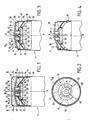
- Figures 1 to 4 show a first embodiment of the present invention in which there is a container, known per se, generally designated by the reference sign 1 and containing a pressurized aerosol.
- This container is of the type with upper opening closed by a circular bowl 2 for mounting a distribution valve from which there is a tubular control rod 3 defining a longitudinal axis X-X.
- the bowl 2 is fixed to the opening of the container by a crimping bead 4.
- the device according to the invention comprises lever means for actuating the valve, these means comprising two separate parts.
- the first part is constituted by a push button indicated overall by the reference 10.
- the second part comprises a fixing ring on the container, indicated overall by the reference 11.
- the push button 10 is a molded piece in one piece, in particular in a thermoplastic material.
- the push button 10 has an external face 15 of generally frustoconical shape of revolution, constituting an application zone 15 a , extending over more than 180 ° around the axis XX, for an actuating force of the valve .
- This face 15 is bordered at its periphery by an edge face 16 forming a cylindrical segment of revolution around the axis XX.
- the diameter of this cylindrical face 16 is less than that of the cylindrical container 1.
- the push button 10 has an internal face 17 corresponding to the face 15 and which is parallel to it.
- This internal face 17 of the push button defines a concave space generally opposite the container.
- the two faces 15 and 17 determine between them a wall 18 of generally constant thickness.
- the edge face 16 also corresponds to a parallel cylindrical internal face 19. The latter together determine a cylindrical wall of substantially constant thickness.
- the push button 10 comprises a cylindrical stud 20 of revolution of axis XX and in one piece with the wall 18.
- This stud 20 has at its upper part adjacent to the wall 18 a nozzle 21 whose axis is oriented substantially in a radial direction.
- This nozzle 21 is connected to a longitudinal channel 22 of axis X-X which opens at the lower end of said stud.
- This end comprises a frustoconical recess 23 which overlaps the end 24 of the control rod in abutment in a fluid connection link.
- the frustoconical shape of the recess 23 allows a certain inclination of the stud 20 relative to the axis of the control rod 3. This inclination nevertheless allows a connection connection between the end 24 of the rod and the nozzle 21.
- the stud is made of a resiliently deformable thermoplastic material to ensure good connection contact between the end of the rod and the frustoconical recess of the stud.
- a generally cylindrical sleeve 30 projects into the concave part defined by the internal face 17 of the push button.
- This cylindrical sleeve 30 of revolution about the axis XX surrounds at least part of the stud 20 and has, in the vicinity of its open end towards the container 1, a projecting radial shoulder 31 generally forming a circular ring whose outer contour forms a support circle 32 capable of cooperating with the complementary abutment means of the ring 11.
- the shoulder 31 is continued by a frustoconical side face 33 converging towards the open end 34 of the sleeve 30.
- the ring 11 has a first cylindrical external upper wall 35. This wall is continued by a shoulder 36, projecting radially, which is extended by a second cylindrical outer wall 37. The ring 11 is delimited by an upper circular edge 38 and a lower circular edge 39. The circular edge 39 comes to bear on a rim of the container 1.
- the first wall 35 is secured to an internal wall 40 to the ring 11.
- This wall 40 has the overall shape of a cone section converging upwards.
- This internal wall 40 is delimited at its upper part by a circular wall 41 comprising a circular opening 42 of axis X-X. This circular opening 42 has a radius greater than the outside radius of the sleeve 30 but less than the radius of the support circle 32.
- This circular wall 41 is delimited by an upper face 43 and a lower planar face 44, abutting for the shoulder 31 and the support circle 32.
- This lower planar face 44 is substantially orthogonal to the axis XX.
- the wall 40 which defines a concave space opposite the upper end of the container 1, is integral in one piece with a wall 45 in the form of a cylindrical ring which ends, towards the container, by a radial rim 46 delimiting a circular orifice 47.
- the radial rim 46 engages under the bead 4 to constitute the means for fixing the ring 11 to the container 1 in cooperation with the circular edge 39 of the ring 11.
- the face of the edge 16 of the push button engages inside the space defined by the upper end of the wall 35 of the ring 11.
- the radius of the support circle 32 is less than the radius of the circular bowl 4.
- a removable cover 50 in the form of a cylindrical cap can come to cover the device, by sliding on the external cylindrical face of the wall 35 of the ring 11 .
- the wall 18 of the push-button 10 and a part of the socket 30 are interrupted by two radial edges which define an angular sector greater than or equal to the angular sector of the jet exiting in operation from the nozzle 21
- the radial edges of the wall 18 continue downwards by two flat walls 51 and 52 which join the stud 20 and which end in a wall 53 in a circular sector substantially orthogonal to the axis XX and in one piece with the nipple 20 in an area close to its lower end.
- the generally circular lower end of the sleeve 30 continues in one piece with the wall 53 under the underside of the latter.
- the sleeve 30 and the circular ring 31 are divided into several segments by interstices.
- the walls 51, 52, 53 create in front of the nozzle a hollow area for the passage of the ejection cone.
- the mounting of the device on the container 1 is carried out as follows.
- the ring 11 is placed in position on the end of the container 1 by snap-fastening of the radial rim 46 on the bead 4 in the re-entrant part of the container included under the said bead.
- the push button 10 is fixed in the circular opening 42 of the ring, making this opening 42 pass through the shoulder 31 of the sleeve 30. This crossing is facilitated by the presence of interstices on the sleeve and the shoulder 31.
- FIG. 3 and 4 show the operation of the device according to the present invention.
- An actuating force (F) is applied to the left part of the application zone 15 a of the push button.
- the push button 10 tilts and, on the left side, penetrates slightly inside the ring 11.
- the support circle 32 then comes to bear opposite to the right, on the stop constituted by the flat face 44 of abutment of the ring 11.
- the stud 20 presses on the end of the control rod 3 and pushes it into the valve, which has the effect of starting the release of the product contained in the container 1.
- FIG. 3 shows a more significant tilting of the push button relative to the control rod 3, which has caused it to sink deeper into the valve and to open it more completely.
- Figures 5 and 6 show a second embodiment of the device according to the invention.
- the corresponding parts of those of the previous embodiment have reference numbers increased by 100.
- the essential difference is that the dispensing nozzle 121 is formed substantially in the center of the external face 115 of the push button 110 in the extension of channel 122 and along axis XX.
- the central part of the wall 118 of the push-button has a thickening, thanks to which a cylindrical recess 200 has been formed, into which the nozzle 121. opens.
- This cylindrical recess constitutes a small reservoir for small quantities of substance to be dispensing which could, at the end of an actuation of this valve, remain in contact with and in the vicinity of the dispensing nozzle 121, and thus, prevent any contamination of the bearing areas by this product.
- the angular extent of the application area 115 a is 360 °.
- FIG. 6 shows that in this embodiment, the sleeve 130 and the shoulder 131, forming a circular ring, have been divided into four segments by four interstices 201.
- the mounting of this device and its operation are in all points similar to those which have been previously described.
- the nozzle projects in the case where the container 101 is an aerosol can, a jet of conical shape whose axis then corresponds to the longitudinal axis X-X.
Landscapes
- Chemical & Material Sciences (AREA)
- Dispersion Chemistry (AREA)
- Engineering & Computer Science (AREA)
- Mechanical Engineering (AREA)
- Containers And Packaging Bodies Having A Special Means To Remove Contents (AREA)
- Nozzles (AREA)
- Mechanically-Actuated Valves (AREA)
- Preventing Unauthorised Actuation Of Valves (AREA)
Applications Claiming Priority (2)
| Application Number | Priority Date | Filing Date | Title |
|---|---|---|---|
| FR9005649A FR2661661B1 (fr) | 1990-05-04 | 1990-05-04 | Dispositif d'actionnement d'une valve de distribution. |
| FR9005649 | 1990-05-04 |
Publications (2)
| Publication Number | Publication Date |
|---|---|
| EP0455552A1 true EP0455552A1 (de) | 1991-11-06 |
| EP0455552B1 EP0455552B1 (de) | 1993-11-03 |
Family
ID=9396340
Family Applications (1)
| Application Number | Title | Priority Date | Filing Date |
|---|---|---|---|
| EP91401134A Expired - Lifetime EP0455552B1 (de) | 1990-05-04 | 1991-04-29 | Betätigungsvorrichtung für Ausgabeventil |
Country Status (6)
| Country | Link |
|---|---|
| EP (1) | EP0455552B1 (de) |
| JP (1) | JP3069924B2 (de) |
| CA (1) | CA2041711C (de) |
| DE (1) | DE69100582T2 (de) |
| ES (1) | ES2046869T3 (de) |
| FR (1) | FR2661661B1 (de) |
Cited By (11)
| Publication number | Priority date | Publication date | Assignee | Title |
|---|---|---|---|---|
| EP0556128A1 (de) * | 1992-02-14 | 1993-08-18 | L'oreal | Betätigungsvorrichtung für ein Ausgabeelement wie zum Beispiel eine Pumpe oder ein Ventil |
| FR2714032A1 (fr) * | 1993-12-17 | 1995-06-23 | Oreal | Dispositif pour actionner une valve de distribution. |
| FR2716445A1 (fr) * | 1994-02-24 | 1995-08-25 | Oreal | Dispositif pour actionner une valve de distribution, et bouton-poussoir pour un tel dispositif. |
| WO1996003335A1 (es) * | 1994-07-28 | 1996-02-08 | Artebel, S.L. | Un dispositivo pulsador y aplicador de liquidos |
| FR2723926A1 (fr) * | 1994-08-30 | 1996-03-01 | Oreal | Distributeur de produit liquide ou cremeux sous pression muni d'un bouton-poussoir equipe d'un systeme de non-violation |
| EP0757007A1 (de) * | 1995-08-01 | 1997-02-05 | Valois S.A. | Befestigungsring mit Doppelindexiervorrichtung |
| US5899623A (en) * | 1995-07-13 | 1999-05-04 | L'oreal | Device for dispensing a substance stored under pressure |
| EP0928750A1 (de) * | 1998-01-09 | 1999-07-14 | The Procter & Gamble Company | Druckbehälter mit Düse und Zusatzelement |
| US6056467A (en) * | 1995-08-08 | 2000-05-02 | L'oreal | Assembly for dispensing a liquid product through a product dispensing member |
| GB2364660A (en) * | 2000-07-14 | 2002-02-06 | Douglas Roger Cooper | Cap for an aerosol container |
| US20220258953A1 (en) * | 2020-12-30 | 2022-08-18 | Jong Pyo PARK | Container for Beverage |
Families Citing this family (1)
| Publication number | Priority date | Publication date | Assignee | Title |
|---|---|---|---|---|
| JP6958578B2 (ja) * | 2019-02-21 | 2021-11-02 | 花王株式会社 | 肌状態計測装置 |
Citations (3)
| Publication number | Priority date | Publication date | Assignee | Title |
|---|---|---|---|---|
| FR2128223A1 (de) * | 1971-03-12 | 1972-10-20 | Oreal | |
| FR2164439A1 (de) * | 1971-12-20 | 1973-08-03 | Ligier Laure | |
| GB1359152A (en) * | 1971-07-19 | 1974-07-10 | Metal Box Co Ltd | Valve actuators for pressurized dispensers |
-
1990
- 1990-05-04 FR FR9005649A patent/FR2661661B1/fr not_active Expired - Lifetime
-
1991
- 1991-04-29 DE DE69100582T patent/DE69100582T2/de not_active Expired - Fee Related
- 1991-04-29 EP EP91401134A patent/EP0455552B1/de not_active Expired - Lifetime
- 1991-04-29 ES ES199191401134T patent/ES2046869T3/es not_active Expired - Lifetime
- 1991-05-02 CA CA002041711A patent/CA2041711C/fr not_active Expired - Fee Related
- 1991-05-07 JP JP3196193A patent/JP3069924B2/ja not_active Expired - Fee Related
Patent Citations (3)
| Publication number | Priority date | Publication date | Assignee | Title |
|---|---|---|---|---|
| FR2128223A1 (de) * | 1971-03-12 | 1972-10-20 | Oreal | |
| GB1359152A (en) * | 1971-07-19 | 1974-07-10 | Metal Box Co Ltd | Valve actuators for pressurized dispensers |
| FR2164439A1 (de) * | 1971-12-20 | 1973-08-03 | Ligier Laure |
Cited By (21)
| Publication number | Priority date | Publication date | Assignee | Title |
|---|---|---|---|---|
| FR2687382A1 (fr) * | 1992-02-14 | 1993-08-20 | Oreal | Dispositif d'actionnement d'un mecanisme de distribution tel qu'une pompe ou une valve. |
| US5335832A (en) * | 1992-02-14 | 1994-08-09 | L'oreal | Device for activating a dispensing mechanism such as a pump or a valve |
| EP0556128A1 (de) * | 1992-02-14 | 1993-08-18 | L'oreal | Betätigungsvorrichtung für ein Ausgabeelement wie zum Beispiel eine Pumpe oder ein Ventil |
| FR2714032A1 (fr) * | 1993-12-17 | 1995-06-23 | Oreal | Dispositif pour actionner une valve de distribution. |
| FR2716445A1 (fr) * | 1994-02-24 | 1995-08-25 | Oreal | Dispositif pour actionner une valve de distribution, et bouton-poussoir pour un tel dispositif. |
| EP0669268A1 (de) * | 1994-02-24 | 1995-08-30 | L'oreal | Abgabevorrichtung für ein Produkt und Drucktaste für diese Vorrichtung |
| US5692846A (en) * | 1994-07-28 | 1997-12-02 | Artebel, S.L. | Push-button applicator device for dispensing liquids |
| WO1996003335A1 (es) * | 1994-07-28 | 1996-02-08 | Artebel, S.L. | Un dispositivo pulsador y aplicador de liquidos |
| FR2723926A1 (fr) * | 1994-08-30 | 1996-03-01 | Oreal | Distributeur de produit liquide ou cremeux sous pression muni d'un bouton-poussoir equipe d'un systeme de non-violation |
| EP0699596A1 (de) * | 1994-08-30 | 1996-03-06 | L'oreal | Vorrichtung zur Ausgabe von flüssigen oder pastösen Produkten unter Druck, versehen mit einem Garantiebetätigungsknopf |
| US5899623A (en) * | 1995-07-13 | 1999-05-04 | L'oreal | Device for dispensing a substance stored under pressure |
| FR2737471A1 (fr) * | 1995-08-01 | 1997-02-07 | Valois | Bague de fixation a double indexation |
| US5772080A (en) * | 1995-08-01 | 1998-06-30 | Valois S.A. | Fixing ring with dual indexing |
| EP0757007A1 (de) * | 1995-08-01 | 1997-02-05 | Valois S.A. | Befestigungsring mit Doppelindexiervorrichtung |
| US6056467A (en) * | 1995-08-08 | 2000-05-02 | L'oreal | Assembly for dispensing a liquid product through a product dispensing member |
| EP0928750A1 (de) * | 1998-01-09 | 1999-07-14 | The Procter & Gamble Company | Druckbehälter mit Düse und Zusatzelement |
| GB2364660A (en) * | 2000-07-14 | 2002-02-06 | Douglas Roger Cooper | Cap for an aerosol container |
| GB2364660B (en) * | 2000-07-14 | 2002-11-13 | Douglas Roger Cooper | Spray container controlled discharge cap |
| US20220258953A1 (en) * | 2020-12-30 | 2022-08-18 | Jong Pyo PARK | Container for Beverage |
| US11999555B2 (en) * | 2020-12-30 | 2024-06-04 | In Motion Design Inc. | Container for beverage |
| US20240270476A1 (en) * | 2020-12-30 | 2024-08-15 | In Motion Design Inc. | Container for Beverage |
Also Published As
| Publication number | Publication date |
|---|---|
| JPH072283A (ja) | 1995-01-06 |
| FR2661661B1 (fr) | 1992-11-13 |
| FR2661661A1 (fr) | 1991-11-08 |
| ES2046869T3 (es) | 1994-02-01 |
| DE69100582T2 (de) | 1994-06-01 |
| CA2041711C (fr) | 2002-07-16 |
| CA2041711A1 (fr) | 1991-11-05 |
| JP3069924B2 (ja) | 2000-07-24 |
| EP0455552B1 (de) | 1993-11-03 |
| DE69100582D1 (de) | 1993-12-09 |
Similar Documents
| Publication | Publication Date | Title |
|---|---|---|
| EP0486355B1 (de) | Abgabevorrichtung für ein flüssiges bis pastöses Erzeugnis und Halterung für eine solche Abgabevorrichtung | |
| EP1201318B1 (de) | Abgabeeinheit für die gleichzeitige Abgabe von zwei Produkten | |
| EP1380520B1 (de) | Ausgabevorrichtung für einen Behälter mit einem Ventil | |
| EP0540129B1 (de) | Abgabevorrichtung für ein flüssiges Produkt, insbesondere kosmetischer oder pharmazeutischer Art | |
| CA2262135C (fr) | Ensemble de conditionnement et de distribution d'un produit liquide | |
| EP0547925B1 (de) | Vorrichtung zum Abgeben eines Produktes, insbesondere eines aufschäumenden Produktes | |
| EP0714836B1 (de) | Betätigungsvorrichtung für des Abgabeventil eines Aerosolbehälters | |
| EP0323779B1 (de) | Ausgabeverschluss für ein flüssiges oder pastöses Produkt sowie Behälter, versehen mit diesem Verschluss | |
| EP0509872B1 (de) | Vorrichtung zur Diffusion eines flüssigen Produkts in feiner Tröpchenform | |
| EP0667301B1 (de) | Ausgabevorrichtung für Flüssigkeiten oder Pulver | |
| CH651270A5 (fr) | Capot de distribution pour recipient pressurise. | |
| EP0628355B1 (de) | Sprühkopf für pastose Produkte und damit ausgestattete Abgabevorrichtung | |
| FR2802187A1 (fr) | Dispositif de distribution d'un produit, comportant un flacon loge dans un recipient | |
| FR2750022A1 (fr) | Distributeur de produit a organe de manoeuvre rotatif et procede de fabrication | |
| EP0455552B1 (de) | Betätigungsvorrichtung für Ausgabeventil | |
| FR2836843A1 (fr) | Dispositif de distribution a gicleur basculant | |
| EP0850851B1 (de) | Ventil für die Abgabe von unter Druck stehenden Fluiden | |
| EP0669268A1 (de) | Abgabevorrichtung für ein Produkt und Drucktaste für diese Vorrichtung | |
| EP3972929A1 (de) | Getränkespender | |
| EP1588774B1 (de) | Verpackungseinheit mit Spenderkopf mit automatisch schliessender Öffnung | |
| EP0373989B1 (de) | Behälterverschlusskappe mit schwenkbarem Betätigungselement zum Abgeben des Behälterinhalts | |
| EP1661822A1 (de) | Verpackung und Ausgabevorrichtung für ein Produkt | |
| FR2517639A1 (fr) | Capot de distribution pour recipient pressurise et ensemble correspondant | |
| EP0499537B1 (de) | Vorrichtung zur Zerstäubung oder Abgabe eines flüssigen Produktes mit einem Schiebesteigrohr im Saugrohr | |
| FR2727670A1 (fr) | Dispositif pour prelever dans un recipient une dose d'un produit, notamment cosmetique, et pour appliquer cette dose |
Legal Events
| Date | Code | Title | Description |
|---|---|---|---|
| PUAI | Public reference made under article 153(3) epc to a published international application that has entered the european phase |
Free format text: ORIGINAL CODE: 0009012 |
|
| 17P | Request for examination filed |
Effective date: 19910430 |
|
| AK | Designated contracting states |
Kind code of ref document: A1 Designated state(s): BE CH DE ES GB IT LI NL |
|
| 17Q | First examination report despatched |
Effective date: 19921209 |
|
| GRAA | (expected) grant |
Free format text: ORIGINAL CODE: 0009210 |
|
| AK | Designated contracting states |
Kind code of ref document: B1 Designated state(s): BE CH DE ES GB IT LI NL |
|
| PG25 | Lapsed in a contracting state [announced via postgrant information from national office to epo] |
Ref country code: NL Effective date: 19931103 |
|
| ITF | It: translation for a ep patent filed | ||
| REF | Corresponds to: |
Ref document number: 69100582 Country of ref document: DE Date of ref document: 19931209 |
|
| GBT | Gb: translation of ep patent filed (gb section 77(6)(a)/1977) |
Effective date: 19931125 |
|
| REG | Reference to a national code |
Ref country code: ES Ref legal event code: FG2A Ref document number: 2046869 Country of ref document: ES Kind code of ref document: T3 |
|
| NLV1 | Nl: lapsed or annulled due to failure to fulfill the requirements of art. 29p and 29m of the patents act | ||
| PG25 | Lapsed in a contracting state [announced via postgrant information from national office to epo] |
Ref country code: CH Effective date: 19940430 Ref country code: BE Effective date: 19940430 Ref country code: LI Effective date: 19940430 |
|
| PLBE | No opposition filed within time limit |
Free format text: ORIGINAL CODE: 0009261 |
|
| STAA | Information on the status of an ep patent application or granted ep patent |
Free format text: STATUS: NO OPPOSITION FILED WITHIN TIME LIMIT |
|
| 26N | No opposition filed | ||
| BERE | Be: lapsed |
Owner name: L' OREAL Effective date: 19940430 |
|
| REG | Reference to a national code |
Ref country code: CH Ref legal event code: PL |
|
| REG | Reference to a national code |
Ref country code: GB Ref legal event code: IF02 |
|
| PGFP | Annual fee paid to national office [announced via postgrant information from national office to epo] |
Ref country code: DE Payment date: 20070426 Year of fee payment: 17 |
|
| PGFP | Annual fee paid to national office [announced via postgrant information from national office to epo] |
Ref country code: ES Payment date: 20070521 Year of fee payment: 17 |
|
| PGFP | Annual fee paid to national office [announced via postgrant information from national office to epo] |
Ref country code: GB Payment date: 20070425 Year of fee payment: 17 |
|
| PGFP | Annual fee paid to national office [announced via postgrant information from national office to epo] |
Ref country code: IT Payment date: 20070626 Year of fee payment: 17 |
|
| GBPC | Gb: european patent ceased through non-payment of renewal fee |
Effective date: 20080429 |
|
| PG25 | Lapsed in a contracting state [announced via postgrant information from national office to epo] |
Ref country code: DE Free format text: LAPSE BECAUSE OF NON-PAYMENT OF DUE FEES Effective date: 20081101 |
|
| REG | Reference to a national code |
Ref country code: ES Ref legal event code: FD2A Effective date: 20080430 |
|
| PG25 | Lapsed in a contracting state [announced via postgrant information from national office to epo] |
Ref country code: GB Free format text: LAPSE BECAUSE OF NON-PAYMENT OF DUE FEES Effective date: 20080429 |
|
| PG25 | Lapsed in a contracting state [announced via postgrant information from national office to epo] |
Ref country code: ES Free format text: LAPSE BECAUSE OF NON-PAYMENT OF DUE FEES Effective date: 20080430 |
|
| PG25 | Lapsed in a contracting state [announced via postgrant information from national office to epo] |
Ref country code: IT Free format text: LAPSE BECAUSE OF NON-PAYMENT OF DUE FEES Effective date: 20080429 |