EP0455591A1 - Scie de panneaux ayant un système de guidage parallèle pour l'unité de sciage - Google Patents
Scie de panneaux ayant un système de guidage parallèle pour l'unité de sciage Download PDFInfo
- Publication number
- EP0455591A1 EP0455591A1 EP91810306A EP91810306A EP0455591A1 EP 0455591 A1 EP0455591 A1 EP 0455591A1 EP 91810306 A EP91810306 A EP 91810306A EP 91810306 A EP91810306 A EP 91810306A EP 0455591 A1 EP0455591 A1 EP 0455591A1
- Authority
- EP
- European Patent Office
- Prior art keywords
- saw
- saw unit
- guide
- unit
- plate
- Prior art date
- Legal status (The legal status is an assumption and is not a legal conclusion. Google has not performed a legal analysis and makes no representation as to the accuracy of the status listed.)
- Granted
Links
Images


Classifications
-
- B—PERFORMING OPERATIONS; TRANSPORTING
- B23—MACHINE TOOLS; METAL-WORKING NOT OTHERWISE PROVIDED FOR
- B23D—PLANING; SLOTTING; SHEARING; BROACHING; SAWING; FILING; SCRAPING; LIKE OPERATIONS FOR WORKING METAL BY REMOVING MATERIAL, NOT OTHERWISE PROVIDED FOR
- B23D45/00—Sawing machines or sawing devices with circular saw blades or with friction saw discs
- B23D45/02—Sawing machines or sawing devices with circular saw blades or with friction saw discs with a circular saw blade or the stock mounted on a carriage
- B23D45/021—Sawing machines or sawing devices with circular saw blades or with friction saw discs with a circular saw blade or the stock mounted on a carriage with the saw blade mounted on a carriage
- B23D45/024—Sawing machines or sawing devices with circular saw blades or with friction saw discs with a circular saw blade or the stock mounted on a carriage with the saw blade mounted on a carriage the saw blade being adjustable according to depth or angle of cut
-
- B—PERFORMING OPERATIONS; TRANSPORTING
- B23—MACHINE TOOLS; METAL-WORKING NOT OTHERWISE PROVIDED FOR
- B23D—PLANING; SLOTTING; SHEARING; BROACHING; SAWING; FILING; SCRAPING; LIKE OPERATIONS FOR WORKING METAL BY REMOVING MATERIAL, NOT OTHERWISE PROVIDED FOR
- B23D59/00—Accessories specially designed for sawing machines or sawing devices
- B23D59/001—Measuring or control devices, e.g. for automatic control of work feed pressure on band saw blade
- B23D59/002—Measuring or control devices, e.g. for automatic control of work feed pressure on band saw blade for the position of the saw blade
-
- B—PERFORMING OPERATIONS; TRANSPORTING
- B23—MACHINE TOOLS; METAL-WORKING NOT OTHERWISE PROVIDED FOR
- B23Q—DETAILS, COMPONENTS, OR ACCESSORIES FOR MACHINE TOOLS, e.g. ARRANGEMENTS FOR COPYING OR CONTROLLING; MACHINE TOOLS IN GENERAL CHARACTERISED BY THE CONSTRUCTION OF PARTICULAR DETAILS OR COMPONENTS; COMBINATIONS OR ASSOCIATIONS OF METAL-WORKING MACHINES, NOT DIRECTED TO A PARTICULAR RESULT
- B23Q1/00—Members which are comprised in the general build-up of a form of machine, particularly relatively large fixed members
- B23Q1/25—Movable or adjustable work or tool supports
- B23Q1/26—Movable or adjustable work or tool supports characterised by constructional features relating to the co-operation of relatively movable members; Means for preventing relative movement of such members
- B23Q1/262—Movable or adjustable work or tool supports characterised by constructional features relating to the co-operation of relatively movable members; Means for preventing relative movement of such members with means to adjust the distance between the relatively slidable members
-
- B—PERFORMING OPERATIONS; TRANSPORTING
- B27—WORKING OR PRESERVING WOOD OR SIMILAR MATERIAL; NAILING OR STAPLING MACHINES IN GENERAL
- B27B—SAWS FOR WOOD OR SIMILAR MATERIAL; COMPONENTS OR ACCESSORIES THEREFOR
- B27B5/00—Sawing machines working with circular or cylindrical saw blades; Components or equipment therefor
- B27B5/02—Sawing machines working with circular or cylindrical saw blades; Components or equipment therefor characterised by a special purpose only
- B27B5/06—Sawing machines working with circular or cylindrical saw blades; Components or equipment therefor characterised by a special purpose only for dividing plates in parts of determined size, e.g. panels
- B27B5/065—Sawing machines working with circular or cylindrical saw blades; Components or equipment therefor characterised by a special purpose only for dividing plates in parts of determined size, e.g. panels with feedable saw blades, e.g. arranged on a carriage
- B27B5/07—Sawing machines working with circular or cylindrical saw blades; Components or equipment therefor characterised by a special purpose only for dividing plates in parts of determined size, e.g. panels with feedable saw blades, e.g. arranged on a carriage the plate being positioned in a substantially vertical plane
Definitions
- the invention relates to a panel saw as defined in the preamble of the independent claim.
- a saw beam 1 is horizontally displaceably mounted on the frame (not shown) of a panel saw, as can be seen for example from CH-PS 386 095, 621 083 and 659 424.
- a saw unit 2 arranged on the saw beam 1 can be moved vertically along the saw beam 1 on the one hand in the direction of the arrow P1, and on the other hand pivoted about an axis A by 90 ° in the direction of the double arrow P2.
- Another movement that can be carried out with the saw unit is the so-called immersion and immersion, wherein the electric motor-driven saw blade is moved towards or away from the clippings.
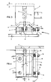
- a stop member 4 is fastened to the saw beam 1, which can be designed, for example, as a solid plastic block and has two stops 4a and 4b projecting downward on its lower edge.
- the stop member 4 is elastically supported by means of a spring 5, which is arranged in a bore 5a of the same, in such a way that it can deflect elastically upwards by the dimension a (FIG. 3) as long as a correspondingly upward force acts on it. In this upper alternative position, the stop member 4 then assumes the position indicated by broken lines.
- a metal guide plate 6 is also connected to the stop member 4, but is offset from the stops 4a and 4b below the plane of the drawing in the direction of the immersion movement, so that it can only come into contact with the saw unit when it is moved in the immersion direction.
- two practically identical guide devices 3 and 3a are fastened, which are offset from one another by 90 ° and are intended to cooperate with the stop member 4 and its guide plate 6 in the horizontal and vertical sectional position of the saw unit, in order to initially position the unit in its rest position secure and then guide it during the insertion and removal process.
- each of the devices 3 and 3a has a base plate 9 (FIGS. 2 to 4) on which two metal plates 11 and 12 delimiting a groove 10 are arranged.
- the metal plate 11 is rigidly attached to the base plate 9 by means of two screws 13 and 14, but its position relative to the base plate can be adjusted by known means.
- the screw 14 also forms the axis for receiving a ball bearing, not shown, which serves to support a roller 15. The position of the roller 15 with respect to the rigid plate 11 is selected so that it protrudes by a small amount b (FIG. 4) over the inner edge of the plate into the groove 10.
- the plate 11 in contrast to the plate 12, extends only up to the vertical projection of the stop member 4, so that the plate 11 does not lie in the region of the stops 4a / 4b when the saw unit is in the immersed state.
- the plate 12 delimiting the groove 10 on the opposite side is movably mounted on a parallel guide (not shown) known to the person skilled in the art and is elastically supported by two coil springs 16 and 17.
- the latter are arranged on the circumference of two screws which are anchored by nuts 18 and 19 to a web 9a (FIG. 3) of the base plate 9.
- the plate 12, which is elastically supported in this way, can thus yield under load in the direction of the base plate web 9a, but will return to its original position under the influence of the relatively strongly designed springs 16 and 17 as soon as no external forces act on it.
- a roller 20 is also rotatably mounted on the plate 12 by means of a ball bearing (not shown), which likewise projects into the groove 10 by a small amount c.
- the mutual distance d between the two rollers is selected such that it is preferably somewhat smaller, but in no case greater than the thickness e of the guide plate 6.
- a burr-shaped stop wedge 21 is formed on the plate 12.
- the stop 4b (FIG. 3) will first strike the stop wedge 21, the associated shock being intercepted and damped by the springs 16 and 17 . Since the stop member 4 itself is elastically resilient, the stop 4b can pass the stop wedge 21 and then assume the position shown in FIG. 3. In this position, the saw unit 2, which is still in the immersed position, is secured against unintentional pivoting and could only be pivoted out of this position by overcoming the elastic restoring force exerted by the spring 5.
- the guide plate 6 enters the groove 10 between the two rollers 15 and 20 and is pressed against the fixed roller 15 by the elastically preloaded roller 20.
- the latter can be adjusted by known means so that it guides the saw blade exactly in the desired - horizontal or vertical - cutting plane.
Landscapes
- Engineering & Computer Science (AREA)
- Mechanical Engineering (AREA)
- Life Sciences & Earth Sciences (AREA)
- Wood Science & Technology (AREA)
- Forests & Forestry (AREA)
- Sawing (AREA)
- Road Signs Or Road Markings (AREA)
Priority Applications (1)
| Application Number | Priority Date | Filing Date | Title |
|---|---|---|---|
| AT91810306T ATE93760T1 (de) | 1990-05-02 | 1991-04-24 | Plattensaege mit parallelfuehrung des saegeaggregates. |
Applications Claiming Priority (2)
| Application Number | Priority Date | Filing Date | Title |
|---|---|---|---|
| CH1490/90 | 1990-05-02 | ||
| CH149090 | 1990-05-02 |
Publications (2)
| Publication Number | Publication Date |
|---|---|
| EP0455591A1 true EP0455591A1 (fr) | 1991-11-06 |
| EP0455591B1 EP0455591B1 (fr) | 1993-09-01 |
Family
ID=4211684
Family Applications (1)
| Application Number | Title | Priority Date | Filing Date |
|---|---|---|---|
| EP91810306A Expired - Lifetime EP0455591B1 (fr) | 1990-05-02 | 1991-04-24 | Scie de panneaux ayant un système de guidage parallèle pour l'unité de sciage |
Country Status (4)
| Country | Link |
|---|---|
| EP (1) | EP0455591B1 (fr) |
| AT (1) | ATE93760T1 (fr) |
| DE (1) | DE59100340D1 (fr) |
| ES (1) | ES2043462T3 (fr) |
Cited By (1)
| Publication number | Priority date | Publication date | Assignee | Title |
|---|---|---|---|---|
| CN115726239A (zh) * | 2022-12-09 | 2023-03-03 | 广东众强建设工程有限公司 | 一种预应力路面及其施工方法 |
Citations (8)
| Publication number | Priority date | Publication date | Assignee | Title |
|---|---|---|---|---|
| US2289259A (en) * | 1939-06-17 | 1942-07-07 | Walt Products Corp De | Carriage for cutting or sawing machines |
| US2329905A (en) * | 1942-03-27 | 1943-09-21 | Wehr Steel Company | Grinding apparatus |
| US2590119A (en) * | 1948-02-09 | 1952-03-25 | Ralph R Roemer | Power-operated radial sawing machine |
| US3151642A (en) * | 1961-09-11 | 1964-10-06 | Eugene T Olson | Angularly shiftable saw mount |
| CH386095A (de) * | 1961-03-17 | 1964-12-31 | Striebig Ludwig | Einrichtung zum Zuschneiden und Ausschneiden von Abschnitten aus grösseren Bauplatten |
| US3465615A (en) * | 1967-12-29 | 1969-09-09 | Giddings & Lewis | Precision locating means for machine tools |
| FR2385503A1 (fr) * | 1977-04-01 | 1978-10-27 | Striebig Ludwig | Scie circulaire de panneaux |
| WO1989005709A2 (fr) * | 1987-12-15 | 1989-06-29 | Karl Rumpler | Installation de fabrication |
-
1991
- 1991-04-24 AT AT91810306T patent/ATE93760T1/de not_active IP Right Cessation
- 1991-04-24 DE DE91810306T patent/DE59100340D1/de not_active Expired - Lifetime
- 1991-04-24 EP EP91810306A patent/EP0455591B1/fr not_active Expired - Lifetime
- 1991-04-24 ES ES91810306T patent/ES2043462T3/es not_active Expired - Lifetime
Patent Citations (8)
| Publication number | Priority date | Publication date | Assignee | Title |
|---|---|---|---|---|
| US2289259A (en) * | 1939-06-17 | 1942-07-07 | Walt Products Corp De | Carriage for cutting or sawing machines |
| US2329905A (en) * | 1942-03-27 | 1943-09-21 | Wehr Steel Company | Grinding apparatus |
| US2590119A (en) * | 1948-02-09 | 1952-03-25 | Ralph R Roemer | Power-operated radial sawing machine |
| CH386095A (de) * | 1961-03-17 | 1964-12-31 | Striebig Ludwig | Einrichtung zum Zuschneiden und Ausschneiden von Abschnitten aus grösseren Bauplatten |
| US3151642A (en) * | 1961-09-11 | 1964-10-06 | Eugene T Olson | Angularly shiftable saw mount |
| US3465615A (en) * | 1967-12-29 | 1969-09-09 | Giddings & Lewis | Precision locating means for machine tools |
| FR2385503A1 (fr) * | 1977-04-01 | 1978-10-27 | Striebig Ludwig | Scie circulaire de panneaux |
| WO1989005709A2 (fr) * | 1987-12-15 | 1989-06-29 | Karl Rumpler | Installation de fabrication |
Cited By (1)
| Publication number | Priority date | Publication date | Assignee | Title |
|---|---|---|---|---|
| CN115726239A (zh) * | 2022-12-09 | 2023-03-03 | 广东众强建设工程有限公司 | 一种预应力路面及其施工方法 |
Also Published As
| Publication number | Publication date |
|---|---|
| ATE93760T1 (de) | 1993-09-15 |
| DE59100340D1 (de) | 1993-10-07 |
| ES2043462T3 (es) | 1993-12-16 |
| EP0455591B1 (fr) | 1993-09-01 |
Similar Documents
| Publication | Publication Date | Title |
|---|---|---|
| DE3905600C2 (de) | Verfahren zum Schneiden von Papier sowie Papierschneidemaschine | |
| DE3107199A1 (de) | Vorrichtung zum schneiden und/oder stanzen | |
| DE102011050520A1 (de) | Fliesenschneider | |
| DE2108064C3 (de) | Blechschere | |
| EP2251126B1 (fr) | Coulisseau transversal doté de plaques de butée déplaçables et motorisées pour scies circulaires à banc | |
| WO2003087506A1 (fr) | Porte dotee d'un dispositif de securite | |
| EP0052379A2 (fr) | Dispositif de serrage, notamment étau | |
| DE102019202861A1 (de) | Nicht-klemmender Anschlag für eine Tischkreissäge | |
| DE3026728C2 (de) | Scharnierkonstruktion für Stahlzargen | |
| DE2947581A1 (de) | Blechschneidevorrichtung | |
| CH684687A5 (de) | Schneidwerkzeug. | |
| EP0490268B1 (fr) | Dispositif pour couper des carreaux ou des plaques par exemple tuile | |
| DE3927817C5 (de) | Vorrichtung zur Öffnungsbegrenzung für eine Schwenktür | |
| EP0197140B1 (fr) | Dispositif de coupe et d'encadrement | |
| EP0455591B1 (fr) | Scie de panneaux ayant un système de guidage parallèle pour l'unité de sciage | |
| DE2910508C2 (de) | Sicherheitsbindung für Ski | |
| EP0204023B1 (fr) | Guidage longitudinal, spécialement pour une scie circulaire | |
| DE2732001A1 (de) | Schnittstrecker an mikrotomen | |
| DE2443444C2 (de) | Türfeststeller am unteren Rand eines Türblattes | |
| DE8408489U1 (de) | Schutzvorrichtung fuer holzbearbeitende maschinen | |
| DE69403591T2 (de) | Kombinierte Tisch- und Gehrungssäge | |
| DE10030325C2 (de) | Gleitstück | |
| EP0141279A2 (fr) | Dispositif pour couper les bouts de fils de raccordement de composants dépassant d'une plaquette à circuit imprimé | |
| DE9306314U1 (de) | Vorrichtung zum Zertrennen von Gitterrosten | |
| DE8331882U1 (de) | Scherschneidvorrichtung zum ablaengen offener blech- oder kunststoffprofile |
Legal Events
| Date | Code | Title | Description |
|---|---|---|---|
| PUAI | Public reference made under article 153(3) epc to a published international application that has entered the european phase |
Free format text: ORIGINAL CODE: 0009012 |
|
| AK | Designated contracting states |
Kind code of ref document: A1 Designated state(s): AT BE CH DE DK ES FR GB GR IT LI LU NL SE |
|
| 17P | Request for examination filed |
Effective date: 19911212 |
|
| 17Q | First examination report despatched |
Effective date: 19921217 |
|
| GRAA | (expected) grant |
Free format text: ORIGINAL CODE: 0009210 |
|
| AK | Designated contracting states |
Kind code of ref document: B1 Designated state(s): AT BE CH DE DK ES FR GB GR IT LI LU NL SE |
|
| PG25 | Lapsed in a contracting state [announced via postgrant information from national office to epo] |
Ref country code: BE Effective date: 19930901 Ref country code: DK Effective date: 19930901 Ref country code: GR Free format text: LAPSE BECAUSE OF FAILURE TO SUBMIT A TRANSLATION OF THE DESCRIPTION OR TO PAY THE FEE WITHIN THE PRESCRIBED TIME-LIMIT Effective date: 19930901 Ref country code: SE Effective date: 19930901 |
|
| REF | Corresponds to: |
Ref document number: 93760 Country of ref document: AT Date of ref document: 19930915 Kind code of ref document: T |
|
| GBT | Gb: translation of ep patent filed (gb section 77(6)(a)/1977) |
Effective date: 19930903 |
|
| REF | Corresponds to: |
Ref document number: 59100340 Country of ref document: DE Date of ref document: 19931007 |
|
| ITF | It: translation for a ep patent filed | ||
| ET | Fr: translation filed | ||
| REG | Reference to a national code |
Ref country code: ES Ref legal event code: FG2A Ref document number: 2043462 Country of ref document: ES Kind code of ref document: T3 |
|
| PG25 | Lapsed in a contracting state [announced via postgrant information from national office to epo] |
Ref country code: LU Free format text: LAPSE BECAUSE OF NON-PAYMENT OF DUE FEES Effective date: 19940430 |
|
| PLBE | No opposition filed within time limit |
Free format text: ORIGINAL CODE: 0009261 |
|
| 26N | No opposition filed | ||
| REG | Reference to a national code |
Ref country code: GB Ref legal event code: IF02 |
|
| REG | Reference to a national code |
Ref country code: CH Ref legal event code: PFA Owner name: STRIEBIG AG Free format text: STRIEBIG AG#GROSSMATTE 26A#6014 LITTAU (CH) -TRANSFER TO- STRIEBIG AG#GROSSMATTE 26A#6014 LITTAU (CH) |
|
| PGFP | Annual fee paid to national office [announced via postgrant information from national office to epo] |
Ref country code: FR Payment date: 20100427 Year of fee payment: 20 Ref country code: ES Payment date: 20100406 Year of fee payment: 20 |
|
| PGFP | Annual fee paid to national office [announced via postgrant information from national office to epo] |
Ref country code: AT Payment date: 20100426 Year of fee payment: 20 Ref country code: IT Payment date: 20100427 Year of fee payment: 20 Ref country code: NL Payment date: 20100421 Year of fee payment: 20 |
|
| PGFP | Annual fee paid to national office [announced via postgrant information from national office to epo] |
Ref country code: CH Payment date: 20100427 Year of fee payment: 20 |
|
| PGFP | Annual fee paid to national office [announced via postgrant information from national office to epo] |
Ref country code: DE Payment date: 20100629 Year of fee payment: 20 Ref country code: GB Payment date: 20100401 Year of fee payment: 20 |
|
| REG | Reference to a national code |
Ref country code: DE Ref legal event code: R071 Ref document number: 59100340 Country of ref document: DE |
|
| REG | Reference to a national code |
Ref country code: CH Ref legal event code: PL |
|
| REG | Reference to a national code |
Ref country code: NL Ref legal event code: V4 Effective date: 20110424 |
|
| REG | Reference to a national code |
Ref country code: GB Ref legal event code: PE20 Expiry date: 20110423 |
|
| PG25 | Lapsed in a contracting state [announced via postgrant information from national office to epo] |
Ref country code: GB Free format text: LAPSE BECAUSE OF EXPIRATION OF PROTECTION Effective date: 20110423 Ref country code: NL Free format text: LAPSE BECAUSE OF EXPIRATION OF PROTECTION Effective date: 20110424 |
|
| REG | Reference to a national code |
Ref country code: ES Ref legal event code: FD2A Effective date: 20120206 |
|
| PG25 | Lapsed in a contracting state [announced via postgrant information from national office to epo] |
Ref country code: ES Free format text: LAPSE BECAUSE OF EXPIRATION OF PROTECTION Effective date: 20110425 |
|
| PG25 | Lapsed in a contracting state [announced via postgrant information from national office to epo] |
Ref country code: DE Free format text: LAPSE BECAUSE OF EXPIRATION OF PROTECTION Effective date: 20110424 |