EP0455671B1 - Motorgetriebenes befestigungswerkzeug - Google Patents
Motorgetriebenes befestigungswerkzeug Download PDFInfo
- Publication number
- EP0455671B1 EP0455671B1 EP90902122A EP90902122A EP0455671B1 EP 0455671 B1 EP0455671 B1 EP 0455671B1 EP 90902122 A EP90902122 A EP 90902122A EP 90902122 A EP90902122 A EP 90902122A EP 0455671 B1 EP0455671 B1 EP 0455671B1
- Authority
- EP
- European Patent Office
- Prior art keywords
- sear
- firing
- firing pin
- pin
- barrel
- Prior art date
- Legal status (The legal status is an assumption and is not a legal conclusion. Google has not performed a legal analysis and makes no representation as to the accuracy of the status listed.)
- Expired - Lifetime
Links
- 238000010304 firing Methods 0.000 claims abstract description 83
- 230000007246 mechanism Effects 0.000 claims abstract description 24
- 239000002360 explosive Substances 0.000 claims abstract description 6
- 230000006835 compression Effects 0.000 claims description 7
- 238000007906 compression Methods 0.000 claims description 7
- 238000006073 displacement reaction Methods 0.000 claims description 5
- 239000000758 substrate Substances 0.000 claims description 4
- 238000010276 construction Methods 0.000 description 2
- 238000005474 detonation Methods 0.000 description 1
- 230000000694 effects Effects 0.000 description 1
- 238000003780 insertion Methods 0.000 description 1
- 230000037431 insertion Effects 0.000 description 1
- 238000012986 modification Methods 0.000 description 1
- 230000004048 modification Effects 0.000 description 1
- 230000000717 retained effect Effects 0.000 description 1
Images


Classifications
-
- B—PERFORMING OPERATIONS; TRANSPORTING
- B25—HAND TOOLS; PORTABLE POWER-DRIVEN TOOLS; MANIPULATORS
- B25C—HAND-HELD NAILING OR STAPLING TOOLS; MANUALLY OPERATED PORTABLE STAPLING TOOLS
- B25C1/00—Hand-held nailing tools; Nail feeding devices
- B25C1/08—Hand-held nailing tools; Nail feeding devices operated by combustion pressure
- B25C1/10—Hand-held nailing tools; Nail feeding devices operated by combustion pressure generated by detonation of a cartridge
- B25C1/14—Hand-held nailing tools; Nail feeding devices operated by combustion pressure generated by detonation of a cartridge acting on an intermediate plunger or anvil
- B25C1/143—Hand-held nailing tools; Nail feeding devices operated by combustion pressure generated by detonation of a cartridge acting on an intermediate plunger or anvil trigger operated
-
- F—MECHANICAL ENGINEERING; LIGHTING; HEATING; WEAPONS; BLASTING
- F41—WEAPONS
- F41A—FUNCTIONAL FEATURES OR DETAILS COMMON TO BOTH SMALLARMS AND ORDNANCE, e.g. CANNONS; MOUNTINGS FOR SMALLARMS OR ORDNANCE
- F41A19/00—Firing or trigger mechanisms; Cocking mechanisms
- F41A19/06—Mechanical firing mechanisms, e.g. counterrecoil firing, recoil actuated firing mechanisms
- F41A19/12—Sears; Sear mountings
Definitions
- the present invention relates to power actuated fastener tools.
- Power actuated tools for driving a fastener such as a nail, into a substrate, such as a concrete beam conventionally comprise a barrel from which the fastener is expelled by means of a piston driven by detonation of an explosive charge. The charge is fired by release of a firing pin after cocking of the tool.
- the firing pin has a slot of sufficient depth to allow a pawl to be contained within the slot. A spring inside the slot biases the pawl to project out of the slot to engage with, and be retained by, a cocking piece.
- a sear which is connected to the trigger is aligned with the pawl.
- the sear retracts the pawl into the firing pin, thus releasing the firing pin from the cocking piece whereby the firing pin is driven by the firing pin spring towards the explosive charge to fire the power actuated tool.
- the firing pin is of relatively small diameter and the space available for mounting the pawl within the firing pin is limited.
- the space available for mounting the pawl within the firing pin is limited.
- For the tool to perform consistently the fit between the pawl and the slot in the firing pin must be maintained. It has been found that repeated firing results in the pawl wearing against both the cocking piece and the slot wall. This results in the pawl becoming loose within the cocking piece and firing pin. Consequently when the sear applies the upward force upon actuation of the trigger, instead of driving the pawl upward into the slot of the firing pin, the pawl may twist and jam. Thus a greater release force is required which makes actuation of the trigger increasingly difficult. It has also been known for a pawl to jam and then to suddenly, and unexpectedly, release, thus firing the tool, which can be very dangerous.
- the present invention relates to a power actuated tool for driving a fastener into a substrate, comprising a firing mechanism including a firing pin for firing an explosive charge to drive the fastener from a barrel of the tool, spring means for driving the firing pin, and a rotary sear pivotal about an axis parallel to the axis of the firing pin between a position in which the sear engages an abutment surface of the pin whereby to entrain the pin and a released position in which the sear is released from the abutment surface whereby to permit driving of the firing pin towards the charge under the bias of the spring means.
- US-A-2,923,940 there is disclosed such a tool in which the charge is contained in a breach chamber, having two parts which are locked together after insertion of the charge.
- This is known as a locked breach and requires separate locking and unlocking systems for the breach chamber.
- the sear is attached to the breach and when the breach moves rearwardly, the firing pin is entrained by the breach structure to move rearwardly.
- the locked breach represents a relatively complex structure, which leads to complexities in the system required for cocking the tool.
- the tool of the invention is characterised in that the sear is movable in a direction parallel to the axis of the firing pin so as to entrain the pin by engagement with the abutment surface in order to cock the firing mechanism, the barrel is displaceable within a body of the tool, and cocking of the firing mechanism is effected by pressing the front of the barrel against a work surface to displace the barrel rearwardly, the sear being displaced rearwardly by the rearwards displacement of the barrel to thereby cause rearwards displacement of the firing pin against the bias of the spring means with the pin being entrained by the sear.
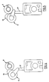
- the power actuated tool 1 comprises a barrel 3 mounted in a receiver assembly 5, and a firing mechanism 7 having a firing pin 9 mounted in the receiver assembly rearwardly of the barrel 3.
- the barrel 3 houses a piston (not shown) which is actuated by an explosive charge mounted in a charge chamber 11 at the rear of the barrel 3, to drive a fastener within the forward end of the barrel 3 into a substrate such as a beam.
- the barrel 3 is mounted for axial movement within the receiver assembly 5 and after firing can be moved forwardly of the receiver assembly 5 in order to reset the piston into the rear end of the barrel 3 in preparation for the next firing.
- a fresh charge is inserted into the charge chamber 11 (either manually or automatically) and the barrel 3 together with the piston is withdrawn into the receiver assembly 5.
- the forward end of the barrel 3 is pressed against the work surface which has the effect of moving the barrel 3 back further into the receiver assembly 5 which causes cocking of the firing mechanism 7.
- the firing pin 9 of the firing mechanism 7 is stepped to provide a forwardly facing abutment face 13.
- the firing pin 9 is biased in an axially forwards direction by means of a compression spring 15.
- the firing pin 9 is associated with a rotary sear 17 which is mounted to one side of the firing pin 9 for rectilinear movement parallel to the axis of the firing pin 9 and also for rotation about the axis of rectilinear movement.
- the sear 17 comprises, at its rear end, a radial lug 19 which co-operates with the firing pin 9 to hold the pin 9 in its cocked position, as will be described.
- a compression spring 21 acts to apply an axially forwards bias to the rotary sear 17 and is also fixed to both the receiver assembly 5 and the sear 17 so as to apply a torsional bias to the sear 17 in a sense to pivot the lug 19 into engagement with the firing pin 9.
- the rotary sear 17 is fixedly mounted at the rear end of a cocking rod 23 so that the sear 17 and cocking rod 23 are movable as a unit.
- a radial lug 25 at the forward end of the cocking rod 23 co-acts with a sear plate 27 of a trigger mechanism 29 in the cocked position, as will be described.
- the trigger mechanism 29 includes a trigger 31.
- the rotary sear 17 is forwardly of the abutment face 13 of the firing pin 9 with the lug 19 being biased towards the firing pin 9 by the torsional bias of the spring 21 .
- the lug 25 at the forward end of the cocking rod 23 is also forwardly of the trigger sear plate 27 in this condition.
- a stepped abutment surface 33 at the rear end of the barrel 3 engages the forward end of the cocking rod 23 and causes the cocking rod and rotary sear 17 to be displaced rearwardly with the barrel 3 against the bias of the spring 21.
- the lug 19 on the rotary sear 17 engages the forward abutment face 13 on the firing pin 9 and causes retraction of the firing pin 9 against the bias of the compression spring 15.
- Actuation of the trigger 31 causes linear displacement of the sear plate 27 which engages the lug 25 and pivots the lug 25 and thus the cocking rod 23 and rotary sear 17 in a sense to move the lug 19 angularly away from the firing pin 9, to thereby release the firing pin 9 which is then driven against the charge in the charge chamber 11 under the bias of the compression spring 15.
- the barrel 3 After firing, the barrel 3 is moved forwardly to reset the piston.
- the forwards movement of the barrel 3 permits the rotary sear 17 and cocking rod 23 to move forwardly under the bias of the spring 21 whereby the lug 19 on the rotary sear 17 moves along the larger diameter rear portion 37 of the firing pin 9 until it reaches the stepped abutment face 13 at which point the torsional bias of the spring 21 causes the lug 19 to pivot inwardly across the abutment face 13 in preparation for the next firing.
- the rotary sear 17 and cocking rod 23 are installed separately and are then locked together to form a unit by means of a connecting pin.
- the components are installed separately and come into that working relation only during the cocking stroke.
- the firing mechanism 7 described is advantageous because there are no components of the release mechanism within the firing pin 9 so the difficulties of mounting the components within the small diameter firing pin 9 and of maintaining the fit between the firing pin 9 and release components are avoided.
- the firing mechanism 7 also provides a very smooth firing action. This is due to the relatively small angle of rotation of the rotary sear 17. The rotation is typically 20° during the firing operation and this results in only a small increase in the torsional force component of the compression spring 21. Accordingly a much smoother searing action is provided.
- the compression spring 21 is relatively long so that it can easily handle this small degree of rotation without jamming.
- firing mechanism 7 is wear-compensating as any wear of the lug 19 against the stepped abutment face 13 will automatically be taken up by the spring bias applied to the firing pin 9 by the firing pin spring.
Landscapes
- Engineering & Computer Science (AREA)
- Chemical & Material Sciences (AREA)
- Combustion & Propulsion (AREA)
- Mechanical Engineering (AREA)
- General Engineering & Computer Science (AREA)
- Portable Nailing Machines And Staplers (AREA)
- Percussive Tools And Related Accessories (AREA)
Claims (7)
- Energiebetätigtes Werkzeug zum Eintreiben eines Verbindungselements in ein Trägermaterial, umfassend einen Zündmechanismus (7), enthaltend einen Zündstift (9) zum Zünden einer Explosionsladung, um das Verbindungselement aus einer Trommel (3) des Werkzeugs zu treiben, Federmittel (15) zum Antreiben des Zündstiftes (9) und eine drehbare Verschlußhammer-Verriegelung (17), die um eine parallel zur Achse des Zündstiftes (9) verlaufende Achse zwischen einer Stellung, in der die Verschlußhammer-Verriegelung (17) an eine Widerlagerfläche (13) des Stiftes (9) greift, um dadurch den Stift (9) mitzureißen, und einer ausgerückten Stellung, in der die Verschlußhammer-Verriegelung (17) von der Widerlagerfläche (13) abgerückt wird, um dadurch das Antreiben des Zündstiftes (9) in Richtung der Ladung unter Vorspannung des Federmittels (15) zu gestatten, drehbar ist, dadurch gekennzeichnet, daß die Verschlußhammer-Verriegelung (17) in einer Richtung parallel zu der Achse des Zündstiftes (9) bewegbar ist, um den Stift (9) durch Eingriff mit der Widerlagerfläche (13) mitzureißen, um den Zündmechanismus (7) zu spannen, die Trommel (3) innerhalb eines Körpers des Werkzeuges verschiebbar ist und das Spannen des Zündmechanismus (7) durch Drücken der Stirnseite der Trommel (3) gegen eine Arbeitsfläche bewirkt wird, um die Trommel (3) nach hinten zu verschieben, wobei die Verschlußhammer-Verriegelung (17) durch die rückwärts gerichtete Verschiebung der Trommel (3) nach hinten verschoben wird, um dabei eine rückwärts gerichtete Verschiebung des Zündstiftes (9) gegen die Vorspannung des Federmittels (15) hervorzurufen, wobei der Stift (9) durch die Verschlußhammer-Verriegelung (17) mitgerissen wird.
- Werkzeug nach Anspruch 1, dadurch gekennzeichnet, daß die Verschlußhammer-Verriegelung (17) im gespannten Zustand des Zündmechanismus (7) mit einem Auslösemechanismus (29) axial ausgerichtet ist, so daS eine Betätigung des Auslösemechanismus (29) die Verschlußhammer-Verriegelung (17) in ihre ausgerückte Stellung verschwenkt.
- Werkzeug nach Anspruch 2, dadurch gekennzeichnet, daß der Auslösemechanismus (29) ein Verschlußhammer-Verriegelungselement (27) umfaßt und die Verschlußhammer-Verriegelung einen Vorsprung (25) aufweist, der mit dem Verschlußhammer-Verriegelungselement (27) fluchtet, wenn die Verschlußhammer-Verriegelung (17) beim Spannen nach hinten bewegt wird, wobei die Betätigung eines Auslösers (31) des Auslösemechanismus einen Eingriff des Verschlußhammer-Verriegelungselements (27) mit dem Vorsprung (25) bewirkt, um die Verschlußhammer-Verriegelung (17) in ihre ausgerückte Stellung zu schwenken.
- Werkzeug nacheinem der vorangehenden Ansprüche, dadurch gekennzeichnet, daß Torsionsfedermittel (21) die Verschlußhammer-Verriegelung (17) in ihre Eingriffsstellung vorspannen.
- Werkzeug nach Anspruch 4, dadurch gekennzeichnet, daß das Torsionsfedermittel (21) eine Druckfeder umfaßt, die eine Torsionsvorspannung und ferner eine nach vorne gerichtete Axialvorspannung auf die Verschlußhammer-Verriegelung (17) ausübt.
- Werkzeug nach einem der vorangehenden Ansprüche, dadurch gekennzeichnet, daß die Verschlußhammer-Verriegelung (17) einen Ansatz (19) umfaßt, der sich radial von der Drehachse der Verschlußhammer-Verriegelung (17) erstreckt, um an die Widerlagerfläche (13) des Zündstiftes (9) anzugreifen.
- Werkzeug nach einem der vorangehenden Ansprüche, dadurch gekennzeichnet, daß die Widerlagerfläche (13) des Zündstiftes (9) durch eine Vorderseite definiert ist, die auf einem Absatz in dem Zündstift ausgebildet ist.
Applications Claiming Priority (3)
| Application Number | Priority Date | Filing Date | Title |
|---|---|---|---|
| AU2401/89 | 1989-01-25 | ||
| AUPJ240189 | 1989-01-25 | ||
| PCT/AU1990/000018 WO1990008628A1 (en) | 1989-01-25 | 1990-01-23 | Power actuated fastener tool |
Publications (3)
| Publication Number | Publication Date |
|---|---|
| EP0455671A1 EP0455671A1 (de) | 1991-11-13 |
| EP0455671A4 EP0455671A4 (en) | 1992-10-28 |
| EP0455671B1 true EP0455671B1 (de) | 1996-06-05 |
Family
ID=3773663
Family Applications (1)
| Application Number | Title | Priority Date | Filing Date |
|---|---|---|---|
| EP90902122A Expired - Lifetime EP0455671B1 (de) | 1989-01-25 | 1990-01-23 | Motorgetriebenes befestigungswerkzeug |
Country Status (7)
| Country | Link |
|---|---|
| US (1) | US5135151A (de) |
| EP (1) | EP0455671B1 (de) |
| AU (1) | AU621456B2 (de) |
| DE (1) | DE69027305T2 (de) |
| HK (1) | HK1002702A1 (de) |
| NZ (1) | NZ232251A (de) |
| WO (1) | WO1990008628A1 (de) |
Families Citing this family (7)
| Publication number | Priority date | Publication date | Assignee | Title |
|---|---|---|---|---|
| FR2680234B1 (fr) * | 1991-08-07 | 1993-11-05 | Georges Mathys | Dispositif de commande multifonction d'arme a feu. |
| US6711842B1 (en) * | 1997-10-31 | 2004-03-30 | Daniel L. Chapman | Firing mechanism |
| US6981630B2 (en) * | 2000-10-12 | 2006-01-03 | Illinois Tool Works Inc. | Cartridge strip advancing mechanism for fastener driving tool |
| AU2002951658A0 (en) * | 2002-09-25 | 2002-10-10 | Cetram Pty Ltd | Explosively actuated tools |
| DE10251307B4 (de) * | 2002-11-04 | 2014-04-10 | Hilti Aktiengesellschaft | Brennkraftbetriebenes Setzgerät |
| US7240448B2 (en) * | 2003-08-21 | 2007-07-10 | Less Lethal, Inc. | Bean bag baton |
| US7237705B2 (en) * | 2004-08-09 | 2007-07-03 | Powers Products Iii, Llc | Firing pin actuation and reset mechanism for a powder actuated setting tool and method |
Citations (1)
| Publication number | Priority date | Publication date | Assignee | Title |
|---|---|---|---|---|
| DE810947C (de) * | 1948-12-24 | 1951-08-16 | Kriegeskorte & Co G M B H | Schlagbolzenspann- und Sicherungsvorrichtung fuer Viehbetaeubungs-apparate, Handfeuerwaffen u. dgl. |
Family Cites Families (20)
| Publication number | Priority date | Publication date | Assignee | Title |
|---|---|---|---|---|
| US2923940A (en) * | 1960-02-09 | Certificate of correction | ||
| FR599153A (fr) * | 1925-06-06 | 1926-01-06 | Dispositif de percussion pour armes à feu | |
| FR836859A (fr) * | 1938-04-20 | 1939-01-27 | Mécanisme simplifié pour constituer les organes essentiels nécessaires à un fusil de chasse à un coup ou à une carabine | |
| CH242371A (de) * | 1943-11-05 | 1946-05-15 | Zbrojovka Brno As | Abzugsvorrichtung für Repetiergewehre. |
| US2512638A (en) * | 1946-07-03 | 1950-06-27 | Alonzo F Gaidos | Fire control selector for automatic firearms |
| US2945236A (en) * | 1953-05-14 | 1960-07-19 | Olin Mathieson | Explosively actuated tools |
| CH344643A (de) * | 1956-08-21 | 1960-02-15 | Konstrukta Praha Narodni Podni | Abzugsvorrichtung an einer Repetierfeuerwaffe mit Zylinderverschluss |
| CH348078A (de) * | 1957-05-01 | 1960-07-31 | Haemmerli Ag Jagd Und Sportwaf | Abzugseinrichtung für Handfeuerwaffen |
| GB892960A (en) * | 1958-06-11 | 1962-04-04 | Marian Karol Jurek | Improvements relating to trigger mechanism of rifles, pistols and like firearms |
| US3048850A (en) * | 1959-03-17 | 1962-08-14 | Arden L Schilling | Universal stud driver |
| FR1252075A (fr) * | 1959-12-03 | 1961-01-27 | Prospection & Inventions | Perfectionnements aux mécanismes de percussion, en particulier pour pistolets de scellement |
| US3248032A (en) * | 1964-01-06 | 1966-04-26 | Hi Shear Corp | Cartridge powered fastener driver |
| US3217441A (en) * | 1964-05-07 | 1965-11-16 | Kerr Raymond William | Practice firearm |
| US3447525A (en) * | 1965-04-26 | 1969-06-03 | Z Jana Svermy Narodni Podnik | Trigger mechanism for automatic weapons |
| DE1728249A1 (de) * | 1968-09-18 | 1972-08-24 | Heckler & Koch Gmbh | Selbstladepistole mit Spannabzug |
| US3548590A (en) * | 1969-03-07 | 1970-12-22 | Star Expansion Ind Corp | Power actuated tool |
| US3816951A (en) * | 1973-01-30 | 1974-06-18 | Gunnabo Bruks Ag | Trigger mechanism for cartridge tool |
| EP0044632B1 (de) * | 1980-07-14 | 1984-10-24 | The Secretary of State for Defence in Her Britannic Majesty's Government of the United Kingdom of Great Britain and | Bedienungsmechanismus für Handfeuerwaffen |
| US4598851A (en) * | 1982-07-02 | 1986-07-08 | Uniset Corporation | Fastener driving tool |
| FR2578639B1 (fr) * | 1985-03-08 | 1989-03-10 | Termet Pierre | Dispositif d'alimentation en cartouches d'un appareil fonctionnant a l'aide d'une charge explosive et chargeur destine a alimenter ledit appareil |
-
1990
- 1990-01-23 EP EP90902122A patent/EP0455671B1/de not_active Expired - Lifetime
- 1990-01-23 HK HK98101877A patent/HK1002702A1/en not_active IP Right Cessation
- 1990-01-23 US US07/721,592 patent/US5135151A/en not_active Expired - Lifetime
- 1990-01-23 DE DE69027305T patent/DE69027305T2/de not_active Expired - Lifetime
- 1990-01-23 AU AU49693/90A patent/AU621456B2/en not_active Expired
- 1990-01-23 WO PCT/AU1990/000018 patent/WO1990008628A1/en not_active Ceased
- 1990-01-25 NZ NZ232251A patent/NZ232251A/en unknown
Patent Citations (1)
| Publication number | Priority date | Publication date | Assignee | Title |
|---|---|---|---|---|
| DE810947C (de) * | 1948-12-24 | 1951-08-16 | Kriegeskorte & Co G M B H | Schlagbolzenspann- und Sicherungsvorrichtung fuer Viehbetaeubungs-apparate, Handfeuerwaffen u. dgl. |
Also Published As
| Publication number | Publication date |
|---|---|
| NZ232251A (en) | 1992-06-25 |
| DE69027305D1 (de) | 1996-07-11 |
| US5135151A (en) | 1992-08-04 |
| EP0455671A4 (en) | 1992-10-28 |
| EP0455671A1 (de) | 1991-11-13 |
| AU621456B2 (en) | 1992-03-12 |
| HK1002702A1 (en) | 1998-09-11 |
| DE69027305T2 (de) | 1996-10-02 |
| WO1990008628A1 (en) | 1990-08-09 |
| AU4969390A (en) | 1990-08-24 |
Similar Documents
| Publication | Publication Date | Title |
|---|---|---|
| US4804127A (en) | Fastener driving gun | |
| US6981630B2 (en) | Cartridge strip advancing mechanism for fastener driving tool | |
| US5114064A (en) | Powder charge operated setting tool | |
| CA2297429C (en) | Explosive powder charge operated setting tool | |
| CA2469579C (en) | Explosively actuated tools | |
| US5135151A (en) | Power actuated fastener tool | |
| US4883042A (en) | Air guns | |
| HK1002702B (en) | Power actuated fastener tool | |
| US6857548B1 (en) | Power actuated tools | |
| US4364506A (en) | Fastener driving tool with cartridge ejector | |
| US5048740A (en) | Fastener setting tools | |
| EP0042070B1 (de) | Von Pulverkraft betriebenes Setzwerkzeug mit Kolben | |
| EP1403006B1 (de) | Explosionskraftbetriebenes Werkzeug | |
| CA2244319A1 (en) | Cocking trigger device | |
| GB1226397A (de) | ||
| US2872682A (en) | Cartridge actuated tool | |
| CA2354477C (en) | Power actuated tools | |
| JPH0123742Y2 (de) | ||
| US3949921A (en) | Fastening gun | |
| US4262578A (en) | Cartridge ejector | |
| CA1051602A (en) | Device for inserting plugs at difficulty accessible points | |
| US3041615A (en) | Inertia operated sear block | |
| AU2003236483B2 (en) | Explosively actuated tools | |
| US20030019902A1 (en) | Cartridge strip advancing mechanism for fastener driving tool | |
| AU765697B2 (en) | Power actuated tools |
Legal Events
| Date | Code | Title | Description |
|---|---|---|---|
| PUAI | Public reference made under article 153(3) epc to a published international application that has entered the european phase |
Free format text: ORIGINAL CODE: 0009012 |
|
| 17P | Request for examination filed |
Effective date: 19910815 |
|
| AK | Designated contracting states |
Kind code of ref document: A1 Designated state(s): DE FR GB IT |
|
| A4 | Supplementary search report drawn up and despatched |
Effective date: 19920910 |
|
| AK | Designated contracting states |
Kind code of ref document: A4 Designated state(s): DE FR GB IT |
|
| 17Q | First examination report despatched |
Effective date: 19950102 |
|
| GRAH | Despatch of communication of intention to grant a patent |
Free format text: ORIGINAL CODE: EPIDOS IGRA |
|
| GRAH | Despatch of communication of intention to grant a patent |
Free format text: ORIGINAL CODE: EPIDOS IGRA |
|
| GRAA | (expected) grant |
Free format text: ORIGINAL CODE: 0009210 |
|
| AK | Designated contracting states |
Kind code of ref document: B1 Designated state(s): DE FR GB IT |
|
| PG25 | Lapsed in a contracting state [announced via postgrant information from national office to epo] |
Ref country code: IT Free format text: LAPSE BECAUSE OF FAILURE TO SUBMIT A TRANSLATION OF THE DESCRIPTION OR TO PAY THE FEE WITHIN THE PRESCRIBED TIME-LIMIT;WARNING: LAPSES OF ITALIAN PATENTS WITH EFFECTIVE DATE BEFORE 2007 MAY HAVE OCCURRED AT ANY TIME BEFORE 2007. THE CORRECT EFFECTIVE DATE MAY BE DIFFERENT FROM THE ONE RECORDED. Effective date: 19960605 Ref country code: FR Effective date: 19960605 |
|
| REF | Corresponds to: |
Ref document number: 69027305 Country of ref document: DE Date of ref document: 19960711 |
|
| EN | Fr: translation not filed | ||
| PLBE | No opposition filed within time limit |
Free format text: ORIGINAL CODE: 0009261 |
|
| STAA | Information on the status of an ep patent application or granted ep patent |
Free format text: STATUS: NO OPPOSITION FILED WITHIN TIME LIMIT |
|
| 26N | No opposition filed | ||
| ET3 | Fr: translation filed ** decision concerning opposition | ||
| REG | Reference to a national code |
Ref country code: GB Ref legal event code: 732E |
|
| REG | Reference to a national code |
Ref country code: GB Ref legal event code: IF02 |
|
| PGFP | Annual fee paid to national office [announced via postgrant information from national office to epo] |
Ref country code: DE Payment date: 20090302 Year of fee payment: 20 |
|
| PGFP | Annual fee paid to national office [announced via postgrant information from national office to epo] |
Ref country code: GB Payment date: 20090129 Year of fee payment: 20 |
|
| REG | Reference to a national code |
Ref country code: GB Ref legal event code: PE20 Expiry date: 20100122 |
|
| PG25 | Lapsed in a contracting state [announced via postgrant information from national office to epo] |
Ref country code: GB Free format text: LAPSE BECAUSE OF EXPIRATION OF PROTECTION Effective date: 20100122 |
|
| PG25 | Lapsed in a contracting state [announced via postgrant information from national office to epo] |
Ref country code: DE Free format text: LAPSE BECAUSE OF EXPIRATION OF PROTECTION Effective date: 20100123 |