EP0455843A1 - Appareil de rétrovision pour véhicules automobiles - Google Patents
Appareil de rétrovision pour véhicules automobiles Download PDFInfo
- Publication number
- EP0455843A1 EP0455843A1 EP90108536A EP90108536A EP0455843A1 EP 0455843 A1 EP0455843 A1 EP 0455843A1 EP 90108536 A EP90108536 A EP 90108536A EP 90108536 A EP90108536 A EP 90108536A EP 0455843 A1 EP0455843 A1 EP 0455843A1
- Authority
- EP
- European Patent Office
- Prior art keywords
- optical conduit
- disposed
- vehicle
- lens
- optical
- Prior art date
- Legal status (The legal status is an assumption and is not a legal conclusion. Google has not performed a legal analysis and makes no representation as to the accuracy of the status listed.)
- Granted
Links
- 230000003287 optical effect Effects 0.000 claims abstract description 71
- 230000000007 visual effect Effects 0.000 abstract description 14
- 238000012986 modification Methods 0.000 description 2
- 230000004048 modification Effects 0.000 description 2
- 231100001261 hazardous Toxicity 0.000 description 1
Images






Classifications
-
- G—PHYSICS
- G02—OPTICS
- G02B—OPTICAL ELEMENTS, SYSTEMS OR APPARATUS
- G02B7/00—Mountings, adjusting means, or light-tight connections, for optical elements
- G02B7/02—Mountings, adjusting means, or light-tight connections, for optical elements for lenses
- G02B7/021—Mountings, adjusting means, or light-tight connections, for optical elements for lenses for more than one lens
-
- B—PERFORMING OPERATIONS; TRANSPORTING
- B60—VEHICLES IN GENERAL
- B60R—VEHICLES, VEHICLE FITTINGS, OR VEHICLE PARTS, NOT OTHERWISE PROVIDED FOR
- B60R1/00—Optical viewing arrangements; Real-time viewing arrangements for drivers or passengers using optical image capturing systems, e.g. cameras or video systems specially adapted for use in or on vehicles
- B60R1/10—Front-view mirror arrangements; Periscope arrangements, i.e. optical devices using combinations of mirrors, lenses, prisms or the like ; Other mirror arrangements giving a view from above or under the vehicle
Definitions
- This invention relates to an optical means to enable a viewer to expand the viewing scope around a visual obstacle, and more particularly to an optical system for a vehicle to enable a driver within the vehicle to see those areas adjacent a rear bumper of the vehicle which are normally not visible by means of conventional rear view mirrors.
- a conventional internal rear view mirror in a vehicle usually has a visual restriction, i.e., it cannot cover the area closely behind the rear bumper.
- This "BLIND" spot to the vision of a driver in the vehicle usually extends five meters of more of ground space beyond the rear bumper.
- Side mounted external mirrors cannot provide a rear view behind the rear bumper at all. The existing of this "BLIND" spot makes driving reverse awkward or even hazardous.
- the present invention embodying these objects comprises several forms and embodiments, all of which utilize an elongated optical conduit in which a multiple number of convex lenses have been purposefully distanced from each other so that the rear view behind the vehicle can be captured, and be formed into a final real and upright image in the front portion of the optical conduit.
- a viewing mirror or reflecting means is provided in front of the optical conduit to enable a driver in the vehicle to see the image in the optical conduit readily.
- FIG.1 Is a schematic side view of a vehicle showing visual coverage afforded by conventional internal and external mirrors.
- FIG.2 Is a schematic top view of a vehicle showing visual coverage afforded by conventional internal and external mirrors.
- FIG.3 Is a schematic side view of the embodiments of the present invention, showing the range of visual coverage on a vehicle.
- FIG.4 Is a sectional side view of an embodiment of the present invention adapted for use on a sedan type automobile.
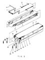
- FIG.5 Is a fragmentary break-up view of another embodiment of the present invention relating to the structure of a foldable optical conduit.
- FIG.6 Is a fragmentary front view of another embodiment of the present invention shown in FIG.5.
- FIG.7 Is another fragmentary front view of another embodiment of the present invention shown in FIG.5.
- FIG.8 Is a fragmentary break-up view of another embodiment of the present invention relating to the structure of lens sets of the foldable optical conduit shown in FIG.5.
- FIG.9 Is a fragmentary front view of another embodiment of the present invention shown in FIG.8.
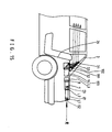
- FIG.10 Is a fragmentary cutaway side view of another embodiment of the present invention, showing actuating frame and lens sets shown in FIG.8.
- FIG.11 Is a fragmentary cutaway side view of another embodiment of the present invention, showing actuating frame and lens sets IN a folded state shown in FIG.8.
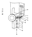
- FIG.12 Is a fragmentary cutaway side view of another embodiment of the present invention showing handle and actuating frame in a folded state shown in FIG.5.
- FIG.13 Is a fragmentary cutaway side view of another embodiment of the present invention showing the handle in an intermediate position shown in FIG.5.
- FIG.14 Is a fragmentary cutaway side view of another embodiment of the present invention showing the handle and actuating frame in a vertical position, shown in FIG.5.
- FIG.15 Is a fragmentary cutaway side view of a further embodiment of the present invention.
- FIG.16 Is a top view of a further embodiment of the present invention shown in FIG.15.
- FIG.17 Is a top view of another embodiment of the present invention.
- FIG.18 Is a fragmentary cutaway side view of another embodiment of the present invention shown in FIG.17.
- FIG.19 Is a fragmentary rear view of another embodiment of the present invention shown in FIG.17.
- FIGS.1 and 2 illustrate the rear visual coverage area of a typical automobile, including a "BLIND" spot shown by a shaded portion.
- This "BLIND" spot usually is not visible by a driver through conventional internal or external rear view mirrors.
- A1 and A2 show the visual boundary of an internal rear view mirror 51,B1 and B2 show the visual boundary of the external rear view mirrors 52.
- the resultant "BLIND" spot behind the vehicle usually cover five meters or more of ground space from rear bumper 83 to boundary A1.
- FIG.3 illustrates the rear visual coverage area after adopting the present invention. depending on the focal lengths of the lenses being used and different types of embodiments, the "BLIND" spot can be reduced to one meter or less.
- C1 and C2 depict the rear visual boundary of an embodiment which affixed underneath vehicle roof; D1 and D2 depict the rear visual boundary of an embodiment which is placed in the rear trunk compartment.
- FIG.4 illustrates an embodiment of the present invention being adopted to a sedan type automobile.
- An optical conduit 1 is longitudinally affixed underneath car roof 2, with its rear opening 1R facing the upper side of rear window 3, and its front opening 1F facing windshield 5.
- object lens L1 is a convex lens with a relatively short focal length and is secured at the rear opening 1R and is able to capture wide angle of picture.
- Transfer lens L2 a convex lens with focal length and diameter greater than that of object lens L1, is located in front of object lens L1 and at a distance greater than the sum of focal lengths L1 and L2.
- Rear view R first forms a real and inverted image I1 after passing through lens L1, then becomes a real and upright image I2 after passing through lens L2.
- Viewing lens L3 is so positioned that its focal point F3 locates beyond image I2, whereby a final magnified, real and upright image I3 will be formed in the front portion of optical conduit 1.
- a viewing mirror 4 is placed in front of the front opening 1F to allow a driver in the front seat of the vehicle to see the image I3, which represents rear view R.
- Mirror 4 is attached underneath vehicle top, or attached to an extension of the optical conduit 1 by means of a bracket 42 and a ball joint 41. This mounting arrangement allows the driver to tilt the viewing mirror 4 to suit his view.
- F1,F2, and F3 are focal points of lens L1, L2 and L3 respectively.
- FIGS.5, 6, and 7 illustrate an embodiment of the present invention which is capable of being folded into a compact size so as to create more headroom in the vehicle.
- This embodiment comprises a top wall 11 which affixed underneath car top, two upper side walls 12,each connecting with a lower side wall 13 via a hinge 14 respectively, a fixed bordering frame 127 is provided outside of each upper side wall 12, a pivot 121 fixed on a front edge of each bordering frame 127, a rocker arm 122 held on the pivot 121, one end of the rocked arm 122 having a slot 123 which engages with a stud 131 attached to a front edge of a lower side wall 13, another end of the rocker arm serves as an actuating lever 124 and being inserted into a curved slot 61 on a slidable actuating frame 6 which is sandwiched between the side wall 12 and the bordering frame 127, a retaining washer 125 which keeps rocker arm 122 on the pivot 121, a tension spring 126 which has one end
- linkage 72 pushes actuating frame 6 in a rearward direction and slot 61 moves actuating lever 124 downward.
- slot 123 of the rocker arm 122 pushes stud 131 downward, thus moving lower side walls 13 from horizontal and folded position to vertical and extended position. Applying same principle in reverse, moving handle 7 back to horizontal position, lower side walls 13 will be moved back to horizontal and folded position.
- FIGS.8,9,10 and 11 illustrate means to fold or extend the lenses in a foldable optical conduit.
- Lens sets L3, L2, and L1 are held respectively in rectangular lens frames 16, 17 and 18, which are transversely held on the upper side walls 12.
- 161 is a supporting spindle
- 128 is a supporting hole on wall 12.
- bottom wall 15 of the optical conduit is formed in a "U" shape cross-section, and is hung on the lower lateral side of the lens frame 16 by a stud pin 163 through a hole 151 on the upward flange of bottom wall 15.same practice applies to lens frames 17 and 18 for hanging bottom wall 15.
- a stud pin 162 On each upper and altear side of lens frame 16 and 17, there is a fixed stud pin 162, 172 which is inserted respectively into slots 129, 130 on the upper side wall 12.
- actuating frame 6 has curved slots 62, 63 which engage with stud pins 162, 172 respectively.
- actuating frames 6 move in rearward direction, and slots 62, 63 move stud pins 162, 172 downward,which in turn move lens frames 16,17 from horizontal position to vertical position.
- Bottom wall 15 will then drag lens frame 18 from a horizontal to a vertical position.
- top wall 11,side walls 12 and 13, and bottom wall 15 will be fully extended to form a rectangular optical conduit.
- actuating frames 6 By moving handle 7 from a vertical position to a horizontal position, actuating frames 6 will firstly move lens frames 16, 17 and 18 into horizontal position through the motion of slots 62 and 63; then the lower side wall 13 will be moved to horizontal and folding position through the motion of of slot 61. thus the whole structure can be packed into a compact size to free up more headroom in the vehicle.
- FIG. 15 and 16 illustrate a further embodiment of the present invention,preferably for vehicle with a rear trunk compartment ,comprising an optical conduit 1.
- an optical conduit 1 which is centrally and longitudinally affixed underneath a trunk lid 81, a multiple number of convex lenses being disposed within said optical conduit, an object lens L1 faces an aperture 82 on a rear lateral wall of the trunk lid 81, a hollow conduit 19 which is placed longitudinally under the rear window shelf 32 and having its rear opening 190 facing the front opening of the optical conduit 1.
- Figs.17, 18 and 19 illustrate another embodiment of the present invention, similar to that shown in figs. 15 and 16 except that instead of placing an optical conduit 1 underneath trunk lid , two optical conduits 1 have been disposed longitudinally along both side walls of a rear trunk compartment. the rear opening of the optical conduit 1 and the object lens L1 point toward an opening in the rear lamp combination 35, thereby can capture rear view R to form a real and upright image I3.
- a hollow conduit 19 connects the front end of optical conduit 1 and is located under a rear window shelt 32.
- An optical means for an automotive vehicle which expands a driver's visual coverage to include areas which are usually not visible by means of conventional rear view mirrors, comprising an elongated optical conduit which contains a multiple number of convex lenses inside, said convex lenses are purposefully distanced from one another,so that outside view closely behind the vehicle can be captured by said optical conduit and to form a magnified real and upright image in the front portion of the optical conduit, a tiltable viewing mirror is provided in front of the optical conduit to enable a driver to view the image in the optical conduit.
- the optical conduit may be placed underneath vehicle top or in a rear trunk compartment.
- the optical conduit may also be made foldable into compact size to reduce headroom intereference in the vehicle.
Landscapes
- Physics & Mathematics (AREA)
- Engineering & Computer Science (AREA)
- General Physics & Mathematics (AREA)
- Optics & Photonics (AREA)
- Multimedia (AREA)
- Mechanical Engineering (AREA)
- Rear-View Mirror Devices That Are Mounted On The Exterior Of The Vehicle (AREA)
Priority Applications (1)
| Application Number | Priority Date | Filing Date | Title |
|---|---|---|---|
| DE1990613673 DE69013673T2 (de) | 1990-05-07 | 1990-05-07 | Rückblickapparat für Kraftfahrzeuge. |
Applications Claiming Priority (1)
| Application Number | Priority Date | Filing Date | Title |
|---|---|---|---|
| US07/258,170 US4961637A (en) | 1988-10-14 | 1988-10-14 | Rear view lens apparatus for automotive vehicle |
Publications (2)
| Publication Number | Publication Date |
|---|---|
| EP0455843A1 true EP0455843A1 (fr) | 1991-11-13 |
| EP0455843B1 EP0455843B1 (fr) | 1994-10-26 |
Family
ID=22979402
Family Applications (1)
| Application Number | Title | Priority Date | Filing Date |
|---|---|---|---|
| EP90108536A Expired - Lifetime EP0455843B1 (fr) | 1988-10-14 | 1990-05-07 | Appareil de rétrovision pour véhicules automobiles |
Country Status (2)
| Country | Link |
|---|---|
| US (1) | US4961637A (fr) |
| EP (1) | EP0455843B1 (fr) |
Cited By (3)
| Publication number | Priority date | Publication date | Assignee | Title |
|---|---|---|---|---|
| WO1996015921A1 (fr) * | 1994-11-22 | 1996-05-30 | Koo Ko | Systeme de retroviseur destine a des vehicules |
| WO1996031365A1 (fr) * | 1995-04-03 | 1996-10-10 | Li Su | Retroviseur destine a un vehicule |
| EP0772078A1 (fr) * | 1995-11-01 | 1997-05-07 | Niles Parts Co., Ltd. | Caméra à multiple-directions |
Families Citing this family (6)
| Publication number | Priority date | Publication date | Assignee | Title |
|---|---|---|---|---|
| DE4134198A1 (de) * | 1991-10-16 | 1993-04-22 | Bayerische Motoren Werke Ag | Rueckblickeinrichtung fuer kraftfahrzeuge |
| GB9124919D0 (en) * | 1991-11-22 | 1992-01-22 | Patel Sunil C | Viewing arrangement |
| US5774280A (en) * | 1995-08-25 | 1998-06-30 | Canon Kabushiki Kaisha | Lens barrel and optical apparatus |
| FR2751430B1 (fr) * | 1996-07-16 | 1998-09-11 | Aerospatiale | Dispositif de suspension et de guidage en translation pour un appareil et appareil equipe d'un tel dispositif |
| JP4364900B2 (ja) * | 2006-12-26 | 2009-11-18 | 本田技研工業株式会社 | セダン型車両の後部車体構造 |
| CN117557660B (zh) * | 2024-01-09 | 2024-04-12 | 北京集度科技有限公司 | 数据处理方法、装置、电子设备以及车辆 |
Citations (3)
| Publication number | Priority date | Publication date | Assignee | Title |
|---|---|---|---|---|
| GB473539A (en) * | 1936-04-16 | 1937-10-15 | Houghton Butcher Mfg Co Ltd | Improvements in and relating to viewing devices especially for aircraft |
| GB1217223A (en) * | 1967-05-23 | 1970-12-31 | Cesare Morais | Rear-view optical system |
| DE2330275A1 (de) * | 1973-06-14 | 1975-01-09 | Werner Dr Ohl | Sicherheitseinrichtung, insbesondere fuer kraftfahrzeuge |
Family Cites Families (11)
| Publication number | Priority date | Publication date | Assignee | Title |
|---|---|---|---|---|
| US1977019A (en) * | 1933-05-27 | 1934-10-16 | Frank L Smith | Rear vision device |
| US2398354A (en) * | 1944-09-11 | 1946-04-16 | Dyron L Brinkley | Motor vehicle periscope |
| US2512792A (en) * | 1948-06-19 | 1950-06-27 | John J Delaney | Rear vision reflector tube for motor vehicles |
| FR1227476A (fr) * | 1959-03-23 | 1960-08-22 | Rétroviseur perfectionné | |
| US3280700A (en) * | 1962-12-06 | 1966-10-25 | Donnelly Mirrors Inc | Periscopic rear view system |
| US3809462A (en) * | 1972-05-12 | 1974-05-07 | Donnelly Mirrors Inc | View expanding and directing optical system |
| US3809461A (en) * | 1972-05-12 | 1974-05-07 | Donnelly Mirrors Inc | View expanding and directing optical system |
| FR2425959A1 (fr) * | 1978-05-17 | 1979-12-14 | Grandbarbe Norbert | Dispositif de controle optique des plages arriere ou avant non visibles par retroviseur pour les vehicules routiers ou de chantier |
| JPS5822831Y2 (ja) * | 1978-07-15 | 1983-05-16 | 岡村 誠 | 自動車用後方監視装置 |
| US4277804A (en) * | 1978-11-01 | 1981-07-07 | Elburn Robison | System for viewing the area rearwardly of a vehicle |
| JPS60213534A (ja) * | 1984-04-06 | 1985-10-25 | Makoto Okamura | 監視装置 |
-
1988
- 1988-10-14 US US07/258,170 patent/US4961637A/en not_active Expired - Fee Related
-
1990
- 1990-05-07 EP EP90108536A patent/EP0455843B1/fr not_active Expired - Lifetime
Patent Citations (3)
| Publication number | Priority date | Publication date | Assignee | Title |
|---|---|---|---|---|
| GB473539A (en) * | 1936-04-16 | 1937-10-15 | Houghton Butcher Mfg Co Ltd | Improvements in and relating to viewing devices especially for aircraft |
| GB1217223A (en) * | 1967-05-23 | 1970-12-31 | Cesare Morais | Rear-view optical system |
| DE2330275A1 (de) * | 1973-06-14 | 1975-01-09 | Werner Dr Ohl | Sicherheitseinrichtung, insbesondere fuer kraftfahrzeuge |
Non-Patent Citations (1)
| Title |
|---|
| PATENT ABSTRACTS OF JAPAN, vol. 4, no. 60 (M-10)[542], 23rd February 1980, page 38 M 10; & JP-A-55 25 665 (HIROKO YABANETA) 06-05-1980 * |
Cited By (7)
| Publication number | Priority date | Publication date | Assignee | Title |
|---|---|---|---|---|
| WO1996015921A1 (fr) * | 1994-11-22 | 1996-05-30 | Koo Ko | Systeme de retroviseur destine a des vehicules |
| WO1996031365A1 (fr) * | 1995-04-03 | 1996-10-10 | Li Su | Retroviseur destine a un vehicule |
| AU686507B2 (en) * | 1995-04-03 | 1998-02-05 | Fuksang So | A rear view mirror unit for a vehicle |
| RU2127201C1 (ru) * | 1995-04-03 | 1999-03-10 | Ли Су | Зеркальный блок заднего вида для транспортного средства |
| US6033078A (en) * | 1995-04-03 | 2000-03-07 | Su; Li | Rear view mirror unit for a vehicle |
| CN1070128C (zh) * | 1995-04-03 | 2001-08-29 | 苏力 | 车辆的后视反射镜机构 |
| EP0772078A1 (fr) * | 1995-11-01 | 1997-05-07 | Niles Parts Co., Ltd. | Caméra à multiple-directions |
Also Published As
| Publication number | Publication date |
|---|---|
| EP0455843B1 (fr) | 1994-10-26 |
| US4961637A (en) | 1990-10-09 |
Similar Documents
| Publication | Publication Date | Title |
|---|---|---|
| US5237459A (en) | Vehicular visual safety device | |
| US5550681A (en) | Rear-mounted vehicle mirror | |
| US6909408B2 (en) | Mounting assembly for night vision display unit | |
| JP2001187547A (ja) | 車両用画像取得及び表示組立体 | |
| US4961637A (en) | Rear view lens apparatus for automotive vehicle | |
| US5127700A (en) | Rear view mirror and sun visor assembly for a vehicle | |
| US3394978A (en) | Dual side split rearview reflecting system | |
| CA2189165A1 (fr) | Retroviseur non deformant a vision de l'angle mort | |
| US6076934A (en) | Vehicle blind spot mirror | |
| US5748395A (en) | Rear view mirror with stowable dual view mirror | |
| US20040046899A1 (en) | Vehicle interior projection entertainment system | |
| US5946150A (en) | Top mount universal swiveling rear view mirror | |
| US4906082A (en) | Lens apparatus for a vehicle | |
| WO1998019888A1 (fr) | Dispositif de securite de la visibilite pour vehicules | |
| GB2177361A (en) | Sideways-viewing mirror assembly for vehicles | |
| US4277142A (en) | Periscopic mirror | |
| JPH04368241A (ja) | 車両用間接視界確認システム | |
| US6179428B1 (en) | Adjustable rearview mirror | |
| WO2005039926A2 (fr) | Dispositif de retrovision pour vehicules | |
| US5109301A (en) | Motor vehicle auxiliary front view mirror | |
| JP3573187B2 (ja) | 車両用周辺視認装置 | |
| US20020186481A1 (en) | Lateral-view mirror assembly for a vehicle | |
| US6431713B1 (en) | Mirror assembly for trucks | |
| KR200311607Y1 (ko) | 자동차용 후사경 | |
| JP3065662U (ja) | モニタ―タイプ自動車後方目視装置 |
Legal Events
| Date | Code | Title | Description |
|---|---|---|---|
| PUAI | Public reference made under article 153(3) epc to a published international application that has entered the european phase |
Free format text: ORIGINAL CODE: 0009012 |
|
| AK | Designated contracting states |
Kind code of ref document: A1 Designated state(s): DE FR GB IT |
|
| 17P | Request for examination filed |
Effective date: 19920508 |
|
| 17Q | First examination report despatched |
Effective date: 19930107 |
|
| GRAA | (expected) grant |
Free format text: ORIGINAL CODE: 0009210 |
|
| AK | Designated contracting states |
Kind code of ref document: B1 Designated state(s): DE FR GB IT |
|
| ITF | It: translation for a ep patent filed | ||
| REF | Corresponds to: |
Ref document number: 69013673 Country of ref document: DE Date of ref document: 19941201 |
|
| ET | Fr: translation filed | ||
| PGFP | Annual fee paid to national office [announced via postgrant information from national office to epo] |
Ref country code: FR Payment date: 19950517 Year of fee payment: 6 |
|
| PGFP | Annual fee paid to national office [announced via postgrant information from national office to epo] |
Ref country code: GB Payment date: 19950522 Year of fee payment: 6 |
|
| PGFP | Annual fee paid to national office [announced via postgrant information from national office to epo] |
Ref country code: DE Payment date: 19950722 Year of fee payment: 6 |
|
| PLBE | No opposition filed within time limit |
Free format text: ORIGINAL CODE: 0009261 |
|
| STAA | Information on the status of an ep patent application or granted ep patent |
Free format text: STATUS: NO OPPOSITION FILED WITHIN TIME LIMIT |
|
| 26N | No opposition filed | ||
| PG25 | Lapsed in a contracting state [announced via postgrant information from national office to epo] |
Ref country code: GB Effective date: 19960507 |
|
| GBPC | Gb: european patent ceased through non-payment of renewal fee |
Effective date: 19960507 |
|
| PG25 | Lapsed in a contracting state [announced via postgrant information from national office to epo] |
Ref country code: FR Effective date: 19970131 |
|
| PG25 | Lapsed in a contracting state [announced via postgrant information from national office to epo] |
Ref country code: DE Effective date: 19970201 |
|
| REG | Reference to a national code |
Ref country code: FR Ref legal event code: ST |
|
| PG25 | Lapsed in a contracting state [announced via postgrant information from national office to epo] |
Ref country code: IT Free format text: LAPSE BECAUSE OF NON-PAYMENT OF DUE FEES;WARNING: LAPSES OF ITALIAN PATENTS WITH EFFECTIVE DATE BEFORE 2007 MAY HAVE OCCURRED AT ANY TIME BEFORE 2007. THE CORRECT EFFECTIVE DATE MAY BE DIFFERENT FROM THE ONE RECORDED. Effective date: 20050507 |