EP0455855A1 - Procédé et dispositif pour fabriquer des prothèses médicales en particulier dentaires - Google Patents
Procédé et dispositif pour fabriquer des prothèses médicales en particulier dentaires Download PDFInfo
- Publication number
- EP0455855A1 EP0455855A1 EP90108743A EP90108743A EP0455855A1 EP 0455855 A1 EP0455855 A1 EP 0455855A1 EP 90108743 A EP90108743 A EP 90108743A EP 90108743 A EP90108743 A EP 90108743A EP 0455855 A1 EP0455855 A1 EP 0455855A1
- Authority
- EP
- European Patent Office
- Prior art keywords
- model
- fitting body
- measuring device
- tool
- measured
- Prior art date
- Legal status (The legal status is an assumption and is not a legal conclusion. Google has not performed a legal analysis and makes no representation as to the accuracy of the status listed.)
- Granted
Links
Images

Classifications
-
- A—HUMAN NECESSITIES
- A61—MEDICAL OR VETERINARY SCIENCE; HYGIENE
- A61C—DENTISTRY; APPARATUS OR METHODS FOR ORAL OR DENTAL HYGIENE
- A61C13/00—Dental prostheses; Making same
- A61C13/0003—Making bridge-work, inlays, implants or the like
- A61C13/0006—Production methods
- A61C13/0009—Production methods using a copying machine
-
- A—HUMAN NECESSITIES
- A61—MEDICAL OR VETERINARY SCIENCE; HYGIENE
- A61C—DENTISTRY; APPARATUS OR METHODS FOR ORAL OR DENTAL HYGIENE
- A61C13/00—Dental prostheses; Making same
- A61C13/0003—Making bridge-work, inlays, implants or the like
- A61C13/0004—Computer-assisted sizing or machining of dental prostheses
-
- G—PHYSICS
- G05—CONTROLLING; REGULATING
- G05B—CONTROL OR REGULATING SYSTEMS IN GENERAL; FUNCTIONAL ELEMENTS OF SUCH SYSTEMS; MONITORING OR TESTING ARRANGEMENTS FOR SUCH SYSTEMS OR ELEMENTS
- G05B19/00—Program-control systems
- G05B19/02—Program-control systems electric
- G05B19/42—Recording and playback systems, i.e. in which the program is recorded from a cycle of operations, e.g. the cycle of operations being manually controlled, after which this record is played back on the same machine
- G05B19/4202—Recording and playback systems, i.e. in which the program is recorded from a cycle of operations, e.g. the cycle of operations being manually controlled, after which this record is played back on the same machine preparation of the program medium using a drawing, a model
- G05B19/4207—Recording and playback systems, i.e. in which the program is recorded from a cycle of operations, e.g. the cycle of operations being manually controlled, after which this record is played back on the same machine preparation of the program medium using a drawing, a model in which a model is traced or scanned and corresponding data recorded
-
- A—HUMAN NECESSITIES
- A61—MEDICAL OR VETERINARY SCIENCE; HYGIENE
- A61C—DENTISTRY; APPARATUS OR METHODS FOR ORAL OR DENTAL HYGIENE
- A61C13/00—Dental prostheses; Making same
- A61C13/0003—Making bridge-work, inlays, implants or the like
- A61C13/0022—Blanks or green, unfinished dental restoration parts
-
- G—PHYSICS
- G16—INFORMATION AND COMMUNICATION TECHNOLOGY [ICT] SPECIALLY ADAPTED FOR SPECIFIC APPLICATION FIELDS
- G16H—HEALTHCARE INFORMATICS, i.e. INFORMATION AND COMMUNICATION TECHNOLOGY [ICT] SPECIALLY ADAPTED FOR THE HANDLING OR PROCESSING OF MEDICAL OR HEALTHCARE DATA
- G16H20/00—ICT specially adapted for therapies or health-improving plans, e.g. for handling prescriptions, for steering therapy or for monitoring patient compliance
- G16H20/40—ICT specially adapted for therapies or health-improving plans, e.g. for handling prescriptions, for steering therapy or for monitoring patient compliance relating to mechanical, radiation or invasive therapies, e.g. surgery, laser therapy, dialysis or acupuncture
Definitions
- the invention relates to a method for producing medical, in particular dental, prosthetic fitting bodies and a device for carrying out the method.
- prosthetic fitting body should be understood here to mean both alloplastic as well as endoprosthetic and exoprosthetic fitting bodies. In the dental field, these can be inlays, onlays, crowns, bridges, prostheses or even implants.
- the procedure is normally that an impression is first taken of the prepared site. Based on the impression, a working model (positive model) is then created in the laboratory, from which a casting model (negative model) is finally made. Wax is applied to the working model, which is usually a plaster model, as a molding material.
- the wax is cut with a suitable contouring tool, e.g. a milling machine, machined. During this process, it must be ensured that the wax layer has a certain minimum thickness on all parts of the peripheral surface.
- Another way of producing prosthetic fitting bodies is that liquid plastic is introduced into a negative mold corresponding to the prosthetic fitting body and the plastic is then, e.g. is polymerized by means of UV rays or heat.
- EP-A-0 182 098 and EP-A-0 054 785 describe a method and a device for producing ready-to-use dental fitting bodies.
- the preparation site in the patient's mouth is scanned with the aid of an optical camera.
- the measured values are then entered into a computer, where they are processed together with further design data to form control data, with which the fitting body is finally made from a suitable material with the aid of a CNC processing machine.
- this method is very advantageous, the technical effort could be reduced even further, in particular because of the relatively complicated structure of the camera.
- the object of the invention specified in claim 1 is to provide a method for creating a prosthetic fitting body which is, in contrast, simpler and less expensive, and an apparatus for carrying out the method.
- the present invention is based on the fact that the optical scanning is not carried out on site at the preparation site, but rather externally in an already existing processing machine, with the aid of which the fitting body is created.
- a relatively simple impression can advantageously be taken, which is either inserted directly into the processing machine as a negative model and then measured three-dimensionally there, or from which a positive model, for example a plaster model, is first created, which is measured in the processing machine.
- a positive model for example a plaster model
- Control signals are formed from the measurement data obtained, with which drive and servomotors for processing tools are controlled, which finally manufacture the fitting body from a workpiece blank in accordance with the contours measured using the model and then calculated.
- the invention is based on the knowledge that the parts which are necessary for the machining of the fitting body and which the processing machine must have, in particular the precisely movable and controllable parts (degrees of freedom) of the processing machine for the measurements of the model.
- the holding and clamping device of the processing machine is used twice, first to hold the model, preferably for optical measurement, and then to hold the workpiece blank for ready-to-use shaping of the fitting body. It is particularly advantageous to carry out the measurement with the aid of an optical measuring device, which can either be fixed in the housing of the processing machine or on an adjustable tool carrier head.
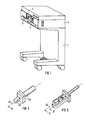
- FIG. 1 shows a diagrammatic representation of the overall arrangement of the device according to the invention in one embodiment for producing a tooth restoration fitting body.
- the device contains a mobile stand 1 with an attached housing 2, which contains a processing machine, generally designated 3. The individual components of this processing machine are described in more detail with reference to the following figure.
- the housing 2 forms a processing chamber 4, which can be closed by means of a preferably transparent cover 5 when the machine is in operation.
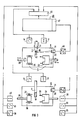
- Figure 2 shows the processing machine seen from above in section.
- the housing 2 accommodates all three components important for the production of the fitting body, namely a receiving device 7, a measuring device 8 and a processing device 9.
- the holding device 7 serves on the one hand to hold a model of the fitting body or of the object in which the fitting body is to be inserted later, and on the other hand (alternatively) to hold a workpiece blank made of a suitable material from which the fitting body is to be made.
- the model can be a positive or negative model of the fitting body or of the object.
- FIG. 4 shows a positive model of a MOD inlay fitting body
- FIG. 5 shows a positive model of a prepared tooth object.
- FIG. 2 shows the processing machine in a phase prepared for processing such a MOD inlay.
- the receiving device 7 is therefore already equipped with a workpiece blank 10, for example made of dental ceramic.
- the receiving device 7 contains a spindle 11 designed as a hollow shaft, which on its end facing away from the workpiece blank 10 has a spindle nut 12 which cooperates with a threaded spindle 13 which is directly coupled to the drive shaft of a drive motor 14 fastened to the housing 2.
- a gear 15 is connected in a rotationally fixed manner to the spindle 11, which gear meshes with a toothed shaft 16, which is mounted between two walls of the housing, which are not described in more detail, and is likewise directly coupled to the drive shaft of a second drive motor 17.
- the drive motor 17 serves to set the spindle 11 in a rotational movement, while a linear movement (longitudinal feed) of the spindle 11 is achieved with the drive 14. If both drive motors 14, 17 run simultaneously, the object held in the front end of the spindle 11 facing the processing chamber 4 by means of a clamping device, generally designated 18, in the present case the workpiece blank 10, is moved spirally. It is understandable that the spindle 11 is guided in a suitable longitudinal and rotary bearing.
- the measuring device 8 consists essentially of a light source 20 which generates a sharply focused light beam which can be aligned with the object held in the receiving device 7, and an optical sensor 21 on which the light spot projected by the light source 20 onto the object is imaged.
- the processing device 9 consists of two mutually opposite spindle arrangements 22 and 35 which, apart from the arrangement of the tools, are of completely identical design. Therefore, only the structure of the spindle arrangement 22 on the right in the figure is explained in more detail below.
- the spindle arrangement 22 contains a spindle 23 designed as a hollow shaft, one of which End protrudes into the processing chamber 4 and carries a tool carrier head 24 there.
- the tool carrier head 24 is connected in a rotationally fixed manner to the spindle 23 and contains in the center an electric motor indicated by 25, the drive shafts on both sides of which drive two similar machining tools 26, 26 'via a gear (not specified).
- a spindle nut 27 is fastened to the spindle 23 and engages with a threaded spindle 29 driven by a drive motor 28. With these drive elements, the spindle 23 can be adjusted in the axial direction.
- the entire tool carrier head 24 can be rotated about the spindle axis, specifically by at least 90 °, but preferably by 180 °.
- a rotation through 90 ° is particularly indicated in order to bring the tool carrier head from the work position shown in the figure, which is suitable for workpiece machining, to a basic or rest position, in which access to the workpiece blank 10 is facilitated on the one hand and no obstruction during measurement on the other hand of the model, as will be explained later, with the aid of the measuring device 20, 21.
- stepper motors as drive motors, which can be controlled in any small step units.
- the stepper motors are provided with feedback.
- Such feedback can consist, for example, in the fact that in the vicinity of the feed spindle, or also coupled to it, on a resistance, capacitance, inductance, ultrasound, magnet and / or optical basis
- Sensor means are provided which are electrically connected to the associated stepper motors via a computer. With the help of such a measuring system, it is possible to increase the accuracy of the spindle movements.
- a fork light barrier 33 is provided on a housing wall, which cooperates with a ring 34 of the gearwheel 30 interrupted by a slot in such a way that the spindle position is exactly defined, both in relation to the Rotational position as well as in relation to the position in the axial direction. While the position in the direction of the feed axis is detected by immersing the ring 34 in the fork light barrier 33, the angular position of the spindle is detected by a signal when the slot 34 interrupting the slot 34 is passed through the light barrier.
- the tool carrier head 36 arranged opposite is constructed identically with regard to the adjustment of the spindle; since the tools held there are not finger-shaped machining tools, as in the case of the tools 26, 26 ', but rather disk-shaped tools (items 37, 37'), the angular gear provided in the tool carrier head 24 is omitted.
- the two drive shafts of the electric motor 38 arranged in the tool carrier head 36 thus drive the two tools 37, 37 'directly.
- the two drive motors for adjusting the spindle 39 (analogous to the spindle 23) are denoted by 40 and 41.
- a positive model is first created from the fitting body to be created, that is to say the MOD inlay.
- an impression is first made of the prepared tooth, in which the fitting body is to be inserted later, and a positive model of the inlay is made from this impression.
- This positive model designated 42 in the upper part of FIG. 3 and shown enlarged in FIG. 4, can be made of plaster or plastic and mounted on a peg-shaped carrier 43.
- the model 42 is inserted with the aid of the carrier 43 with a defined stop into the quick-release device of the receiving device 7, which is denoted by 18. Then the optical measurement of the model begins.
- the light source 20 FIG.
- the model is measured using the triangulation method with a specific (as small as possible) parallax angle between the projection and observation beam path. This method is known per se and is used, for example, in 3-D laser scanners.
- the model is moved spirally with the aid of the spindle 11 and the two servomotors 14 and 17 with sufficient fineness (for example with a pitch of 25 ⁇ m).
- the measured values are digitized in an A / D converter 46 and then fed to a memory 47 of a computing unit 48.
- the measured values are converted into feed values, with which the actuating and drive motors 14, 17, 25, 28, 31, 38, 40, 41 are then controlled via a corresponding interface 49 in the processing phase.
- the workpiece blank designated by 10 in FIG. 2 is inserted into the receiving device 7 (lower image phase in FIG. 3).
- the fitting body is then worked out of the workpiece blank according to the calculated control program with the aid of the two machining tools 26, 37 which are arranged in the tool carrier heads 24 and 36.
- FIG. 5 shows such a positive model of a prepared row of teeth.
- this variant would be technically more complex overall, in particular because of the larger computer that would be required, but it would have certain advantages when creating palate plates for full dentures, because here the impression could be optically scanned as a negative model and directly from this negative model Fit body, i.e. create the palate plate.
- the optical measuring device 20, 21 on one of the tool carrier heads 24, 35.
- the sensor could then be brought into an optimal measuring position via defined movements.
- the movements which are then generated by the movements of the tool spindles are known to the computer and can be superimposed on the actual sensor measured value as a correction.
- the sensor can be designed so that it does not determine a measured value over the distance to the surface of the model, but only signals whether the surface is at a certain distance or not. Then the sensor is moved during the measurement until it is at this certain distance; the measured value of the surface then results from knowledge of the travel path.
- Suitable detectors would be, for example, detectors that work on the principle of the confocal microscope or other focus detectors.
- the movement of the sensor can also be used to measure the model from different viewing directions.
Landscapes
- Health & Medical Sciences (AREA)
- Oral & Maxillofacial Surgery (AREA)
- Dentistry (AREA)
- Epidemiology (AREA)
- Life Sciences & Earth Sciences (AREA)
- Animal Behavior & Ethology (AREA)
- General Health & Medical Sciences (AREA)
- Public Health (AREA)
- Veterinary Medicine (AREA)
- Engineering & Computer Science (AREA)
- Manufacturing & Machinery (AREA)
- Physics & Mathematics (AREA)
- General Physics & Mathematics (AREA)
- Automation & Control Theory (AREA)
- Dental Prosthetics (AREA)
- Machine Tool Sensing Apparatuses (AREA)
Priority Applications (2)
| Application Number | Priority Date | Filing Date | Title |
|---|---|---|---|
| EP90108743A EP0455855B1 (fr) | 1990-05-09 | 1990-05-09 | Procédé et dispositif pour fabriquer des prothèses médicales en particulier dentaires |
| DE59008902T DE59008902D1 (de) | 1990-05-09 | 1990-05-09 | Verfahren und Vorrichtung zur Erstellung von medizinischen, insbesondere zahnmedizinischen Prothetik- Passkörpern. |
Applications Claiming Priority (1)
| Application Number | Priority Date | Filing Date | Title |
|---|---|---|---|
| EP90108743A EP0455855B1 (fr) | 1990-05-09 | 1990-05-09 | Procédé et dispositif pour fabriquer des prothèses médicales en particulier dentaires |
Publications (2)
| Publication Number | Publication Date |
|---|---|
| EP0455855A1 true EP0455855A1 (fr) | 1991-11-13 |
| EP0455855B1 EP0455855B1 (fr) | 1995-04-12 |
Family
ID=8203966
Family Applications (1)
| Application Number | Title | Priority Date | Filing Date |
|---|---|---|---|
| EP90108743A Expired - Lifetime EP0455855B1 (fr) | 1990-05-09 | 1990-05-09 | Procédé et dispositif pour fabriquer des prothèses médicales en particulier dentaires |
Country Status (2)
| Country | Link |
|---|---|
| EP (1) | EP0455855B1 (fr) |
| DE (1) | DE59008902D1 (fr) |
Cited By (13)
| Publication number | Priority date | Publication date | Assignee | Title |
|---|---|---|---|---|
| EP0541500A1 (fr) * | 1991-11-01 | 1993-05-12 | Nobelpharma AB | Dispositif de balayage |
| EP0634149A1 (fr) * | 1993-06-24 | 1995-01-18 | Metoxit Ag | Procédé de fabrication de prothèses |
| WO1996005782A1 (fr) * | 1994-08-19 | 1996-02-29 | Andreas Dahr | Dispositif pour fabriquer des obturations dentaires et similaire |
| EP0543258A3 (en) * | 1991-11-17 | 1996-03-20 | Liconic Ag | Method and device for the production of dental prosthesis |
| WO1997021156A1 (fr) * | 1995-12-05 | 1997-06-12 | Nobel Biocare Ab (Publ) | Dispositif de compression utilise conjointement avec un produit de dentisterie ou un autre produit en relation avec le corps humain, ou outil pour ce produit |
| WO1998040031A1 (fr) * | 1997-03-13 | 1998-09-17 | Heraeus Kulzer Dental Gmbh & Co. Kg | Procede et dispositif de faconnage de pieces en technique dentaire |
| US5910273A (en) * | 1992-11-25 | 1999-06-08 | Vita Zahnfabrik H. Rauter Gmbh & Co. Kg | Process for manufacturing dental prosthetics based on ceramics |
| DE19930859A1 (de) * | 1999-07-05 | 2001-01-18 | Sirona Dental Systems Gmbh | Verfahren zur Erstellung von medizinischen, insbesondere zahnmedizinischen Paßkörpern |
| EP1093768A2 (fr) | 1999-10-21 | 2001-04-25 | Sirona Dental Systems GmbH | Procédé et dispositif de prise d'empreinte optique d'objets médicaux, en particulier de modèles de dents |
| US6427352B1 (en) | 1999-05-07 | 2002-08-06 | Sirona Dental Systems Gmbh | Device to align and mount a workpiece on a holding device |
| WO2003046412A1 (fr) * | 2001-11-27 | 2003-06-05 | Renishaw Plc | Porte-echantillons mobile |
| DE4436231B4 (de) * | 1994-05-05 | 2006-06-01 | Hint-Els Gmbh | Verfahren und Vorrichtung zur Herstellung einer Dentalprothese |
| EP1339345B1 (fr) * | 2000-12-07 | 2009-05-06 | Eidgenössische Technische Hochschule Zürich Nichtmetallische Werkstoffe | Dispositif de retenue pour une ebauche en ceramique |
Families Citing this family (2)
| Publication number | Priority date | Publication date | Assignee | Title |
|---|---|---|---|---|
| DE102006023673B4 (de) * | 2006-05-19 | 2013-07-04 | Institut Straumann Ag | Fraesvorrichtung zum Herstellen von Zahnersatzteilen |
| GB0803666D0 (en) | 2008-02-28 | 2008-04-09 | Renishaw Plc | Indexer |
Citations (6)
| Publication number | Priority date | Publication date | Assignee | Title |
|---|---|---|---|---|
| DE2934658A1 (de) * | 1979-06-28 | 1981-01-15 | Willemin Machines Sa | Verfahren zur erstellung eines in einer werkzeugmaschine einesetzbaren elektronischen programmes |
| EP0025911A1 (fr) * | 1979-09-12 | 1981-04-01 | Paul Dr. Heitlinger | Procédé pour la fabrication de dents artificielles et dispositif pour sa mise en oeuvre |
| EP0091876A1 (fr) * | 1982-04-14 | 1983-10-19 | Duret, François | Dispositif de prise d'empreinte par des moyens optiques, notamment en vue de la réalisation automatique de prothèses |
| EP0163076A1 (fr) * | 1984-04-17 | 1985-12-04 | Kawasaki Jukogyo Kabushiki Kaisha | Dispositif pour réaliser une copie tridimensionelle d'un objet |
| DE3541891A1 (de) * | 1985-11-27 | 1987-06-04 | Kambiz Kachanian | Verfahren zur erfassung, speicherung und wiedergabe von geometrischen daten von objekten, insbesondere von kiefermodellen und eine vorrichtung zur durchfuehrung des verfahrens |
| US4745290A (en) * | 1987-03-19 | 1988-05-17 | David Frankel | Method and apparatus for use in making custom shoes |
-
1990
- 1990-05-09 EP EP90108743A patent/EP0455855B1/fr not_active Expired - Lifetime
- 1990-05-09 DE DE59008902T patent/DE59008902D1/de not_active Expired - Lifetime
Patent Citations (6)
| Publication number | Priority date | Publication date | Assignee | Title |
|---|---|---|---|---|
| DE2934658A1 (de) * | 1979-06-28 | 1981-01-15 | Willemin Machines Sa | Verfahren zur erstellung eines in einer werkzeugmaschine einesetzbaren elektronischen programmes |
| EP0025911A1 (fr) * | 1979-09-12 | 1981-04-01 | Paul Dr. Heitlinger | Procédé pour la fabrication de dents artificielles et dispositif pour sa mise en oeuvre |
| EP0091876A1 (fr) * | 1982-04-14 | 1983-10-19 | Duret, François | Dispositif de prise d'empreinte par des moyens optiques, notamment en vue de la réalisation automatique de prothèses |
| EP0163076A1 (fr) * | 1984-04-17 | 1985-12-04 | Kawasaki Jukogyo Kabushiki Kaisha | Dispositif pour réaliser une copie tridimensionelle d'un objet |
| DE3541891A1 (de) * | 1985-11-27 | 1987-06-04 | Kambiz Kachanian | Verfahren zur erfassung, speicherung und wiedergabe von geometrischen daten von objekten, insbesondere von kiefermodellen und eine vorrichtung zur durchfuehrung des verfahrens |
| US4745290A (en) * | 1987-03-19 | 1988-05-17 | David Frankel | Method and apparatus for use in making custom shoes |
Non-Patent Citations (1)
| Title |
|---|
| KONSERVIERENDE ZAHNHEILKUNDE, Heft 3, März 1987, Seiten 1-14; MÖRMANN et al.: "Das Cerec-System: Computergestützte Herstellung direkter Keramikinlays in einer Sitzung" * |
Cited By (22)
| Publication number | Priority date | Publication date | Assignee | Title |
|---|---|---|---|---|
| US5652709A (en) * | 1991-11-01 | 1997-07-29 | Nobel Biocare Ab | Scanning device for use in manufacturing implants |
| EP0541500A1 (fr) * | 1991-11-01 | 1993-05-12 | Nobelpharma AB | Dispositif de balayage |
| EP0543258A3 (en) * | 1991-11-17 | 1996-03-20 | Liconic Ag | Method and device for the production of dental prosthesis |
| US5910273A (en) * | 1992-11-25 | 1999-06-08 | Vita Zahnfabrik H. Rauter Gmbh & Co. Kg | Process for manufacturing dental prosthetics based on ceramics |
| EP0634149A1 (fr) * | 1993-06-24 | 1995-01-18 | Metoxit Ag | Procédé de fabrication de prothèses |
| DE4436231B4 (de) * | 1994-05-05 | 2006-06-01 | Hint-Els Gmbh | Verfahren und Vorrichtung zur Herstellung einer Dentalprothese |
| WO1996005782A1 (fr) * | 1994-08-19 | 1996-02-29 | Andreas Dahr | Dispositif pour fabriquer des obturations dentaires et similaire |
| WO1996005781A1 (fr) * | 1994-08-19 | 1996-02-29 | Andreas Dahr | Dispositif de fabrication d'obturations dentaires et similaires |
| US6212442B1 (en) | 1995-12-05 | 2001-04-03 | Nobel Biocare Ab | Compressing device in association with a dental product or other product related to the human body, or tool for this product |
| WO1997021156A1 (fr) * | 1995-12-05 | 1997-06-12 | Nobel Biocare Ab (Publ) | Dispositif de compression utilise conjointement avec un produit de dentisterie ou un autre produit en relation avec le corps humain, ou outil pour ce produit |
| WO1998040031A1 (fr) * | 1997-03-13 | 1998-09-17 | Heraeus Kulzer Dental Gmbh & Co. Kg | Procede et dispositif de faconnage de pieces en technique dentaire |
| US6427352B1 (en) | 1999-05-07 | 2002-08-06 | Sirona Dental Systems Gmbh | Device to align and mount a workpiece on a holding device |
| DE19930859A1 (de) * | 1999-07-05 | 2001-01-18 | Sirona Dental Systems Gmbh | Verfahren zur Erstellung von medizinischen, insbesondere zahnmedizinischen Paßkörpern |
| DE19950780A1 (de) * | 1999-10-21 | 2001-05-23 | Sirona Dental Systems Gmbh | Verfahren und Vorrichtung zur Erfassung medizinischer Objekte, insbesondere von Modellen präparierter Zähne |
| EP1093768A3 (fr) * | 1999-10-21 | 2003-05-14 | Sirona Dental Systems GmbH | Procédé et dispositif de prise d'empreinte optique d'objets médicaux, en particulier de modèles de dents |
| DE19950780C2 (de) * | 1999-10-21 | 2003-06-18 | Sirona Dental Systems Gmbh | Verfahren und Vorrichtung zur Erfassung medizinischer Objekte, insbesondere von Modellen präparierter Zähne |
| US6614538B1 (en) | 1999-10-21 | 2003-09-02 | Sirona Dental Systems Gmbh | Method and apparatus for recording medical objects, in particular for recording models of prepared teeth |
| EP1093768A2 (fr) | 1999-10-21 | 2001-04-25 | Sirona Dental Systems GmbH | Procédé et dispositif de prise d'empreinte optique d'objets médicaux, en particulier de modèles de dents |
| EP1339345B1 (fr) * | 2000-12-07 | 2009-05-06 | Eidgenössische Technische Hochschule Zürich Nichtmetallische Werkstoffe | Dispositif de retenue pour une ebauche en ceramique |
| WO2003046412A1 (fr) * | 2001-11-27 | 2003-06-05 | Renishaw Plc | Porte-echantillons mobile |
| US7185552B2 (en) | 2001-11-27 | 2007-03-06 | Renishaw Plc | Movable sample holder |
| CN100353137C (zh) * | 2001-11-27 | 2007-12-05 | 瑞尼斯豪公司 | 可运动样本固定器 |
Also Published As
| Publication number | Publication date |
|---|---|
| EP0455855B1 (fr) | 1995-04-12 |
| DE59008902D1 (de) | 1995-05-18 |
Similar Documents
| Publication | Publication Date | Title |
|---|---|---|
| EP0913130B1 (fr) | Méthode et dispositif pour la fabrication d'une prothèse dentaire | |
| DE69229291T2 (de) | Vorrichtung und Verfahren zum Herstellen einer zahnärtzlichen Füllmasse für die Wiederherstellung von Zahnkronen | |
| DE69124213T2 (de) | Vorrichtung und Verfahren zum Herstellen dreidimensionaler individuell entworfener Objekte, verwendbar als Kunstzähne, Prothesen, etc. | |
| EP0455855B1 (fr) | Procédé et dispositif pour fabriquer des prothèses médicales en particulier dentaires | |
| EP1392174B1 (fr) | Procede et appareil pour extraire de la matiere ou pour travailler de la matiere | |
| EP2261598B1 (fr) | Procédé de placement d'une prothèse dentaire | |
| EP0182098B1 (fr) | Procédé et dispositif pour la fabrication d'un corps restauratif de dent apte à être utilisé individuellement | |
| EP0543258B1 (fr) | Procédé et dispositif pour la fabrication d'une prothèse dentaire | |
| DE4218219C2 (de) | Vorrichtung zum berührungslosen Vermessen eines schlecht zugänglichen, dreidimensionalen medizinischen oder zahntechnischen Objektes | |
| EP1406555B1 (fr) | Procede et dispositif pour mesurer et numeriser en trois dimensions un modele dentaire | |
| DE3712084C2 (de) | Verfahren und Einrichtung zur Herstellung einer modifizierten, dreidimensionalen Reproduktion eines weichen, deformierbaren Objektes | |
| DE602005004716T2 (de) | Verfahren zur Erzeugung von dreidimensionalen Formdaten einer Zahnprothese | |
| EP1793739B1 (fr) | Procede pour determiner la position relative theorique d'un patient dans un appareil radiographique panoramique dentaire et la trajectoire theorique selon laquelle ledit appareil doit etre deplace par rapport a un patient et dispositif approprie a cet effet | |
| EP1523285A1 (fr) | Dispositif de mesure de modeles et machine d'usinage equipee d'un tel dispositif | |
| DD297913A5 (de) | Verfahren und geraete zur herstellung von formkoerpern, insbesondere von inlays, onlays und kronen in der zahnmedizin | |
| EP1245332A1 (fr) | Fraiseuse/meuleuse pour la fabrication de pièces dentaires | |
| EP0033492A1 (fr) | Procédé et dispositif pour la fabrication d'une couronne dentaire | |
| DE4030185A1 (de) | Verfahren zum kalibrieren eines motorisch angetriebenen werkzeuges in bezug auf ein mit diesem zu bearbeitendes werkstueck sowie vorrichtung zur durchfuehrung des verfahrens | |
| EP2303177A1 (fr) | Dispositif d'usinage pour la réalisation d'un gabarit de forage destiné à des implants dentaires | |
| WO1991003980A1 (fr) | Dispositif pour l'exploration d'une region de la cavite buccale | |
| EP0455853B1 (fr) | Dispositif pour la fabrication de prothèses médicales, en particulier prothèses dentaires | |
| DE4030175C2 (de) | Verfahren zum Kalibrieren eines motorisch angetriebenen Werkzeuges in bezug auf ein mit diesem zu bearbeitendes Werkstück sowie Vorrichtung zur Durchführung des Verfahrens | |
| DE3604531A1 (de) | Verfahren zur herstellung von zahnersatzteilen und vorrichtung zur durchfuehrung dieses verfahrens | |
| WO1994024957A1 (fr) | Procede de saisie de donnees concernant la disposition/structure des dents, dispositif et porte-empreinte de mise en ×uvre du procede | |
| DE4030176A1 (de) | Verfahren zum kalibrieren eines motorisch angetriebenen werkzeuges in bezug auf ein mit diesem zu bearbeitendes werkstueck sowie vorrichtung zur durchfuehrung des verfahren |
Legal Events
| Date | Code | Title | Description |
|---|---|---|---|
| PUAI | Public reference made under article 153(3) epc to a published international application that has entered the european phase |
Free format text: ORIGINAL CODE: 0009012 |
|
| 17P | Request for examination filed |
Effective date: 19901205 |
|
| AK | Designated contracting states |
Kind code of ref document: A1 Designated state(s): CH DE FR IT LI SE |
|
| 17Q | First examination report despatched |
Effective date: 19931221 |
|
| GRAA | (expected) grant |
Free format text: ORIGINAL CODE: 0009210 |
|
| AK | Designated contracting states |
Kind code of ref document: B1 Designated state(s): CH DE FR IT LI SE |
|
| REF | Corresponds to: |
Ref document number: 59008902 Country of ref document: DE Date of ref document: 19950518 |
|
| ITF | It: translation for a ep patent filed | ||
| ET | Fr: translation filed | ||
| PLBE | No opposition filed within time limit |
Free format text: ORIGINAL CODE: 0009261 |
|
| STAA | Information on the status of an ep patent application or granted ep patent |
Free format text: STATUS: NO OPPOSITION FILED WITHIN TIME LIMIT |
|
| 26N | No opposition filed | ||
| REG | Reference to a national code |
Ref country code: CH Ref legal event code: PUE Owner name: SIEMENS AKTIENGESELLSCHAFT TRANSFER- SIRONA DENTAL |
|
| REG | Reference to a national code |
Ref country code: FR Ref legal event code: TP |
|
| REG | Reference to a national code |
Ref country code: CH Ref legal event code: PFA Free format text: SIRONA DENTAL SYSTEMS GMBH & CO.KG TRANSFER- SIRONA DENTAL SYSTEMS GMBH Ref country code: CH Ref legal event code: NV Representative=s name: SCHMAUDER & PARTNER AG PATENTANWALTSBUERO |
|
| PG25 | Lapsed in a contracting state [announced via postgrant information from national office to epo] |
Ref country code: IT Free format text: LAPSE BECAUSE OF NON-PAYMENT OF DUE FEES;WARNING: LAPSES OF ITALIAN PATENTS WITH EFFECTIVE DATE BEFORE 2007 MAY HAVE OCCURRED AT ANY TIME BEFORE 2007. THE CORRECT EFFECTIVE DATE MAY BE DIFFERENT FROM THE ONE RECORDED. Effective date: 20050509 |
|
| PGRI | Patent reinstated in contracting state [announced from national office to epo] |
Ref country code: IT Effective date: 20080301 |
|
| REG | Reference to a national code |
Ref country code: CH Ref legal event code: PCAR Free format text: SCHMAUDER & PARTNER AG PATENT- UND MARKENANWAELTE VSP;ZWAENGIWEG 7;8038 ZUERICH (CH) |
|
| PGFP | Annual fee paid to national office [announced via postgrant information from national office to epo] |
Ref country code: DE Payment date: 20090526 Year of fee payment: 20 Ref country code: FR Payment date: 20090519 Year of fee payment: 20 Ref country code: SE Payment date: 20090519 Year of fee payment: 20 Ref country code: IT Payment date: 20090522 Year of fee payment: 20 |
|
| PGFP | Annual fee paid to national office [announced via postgrant information from national office to epo] |
Ref country code: CH Payment date: 20090525 Year of fee payment: 20 |
|
| REG | Reference to a national code |
Ref country code: CH Ref legal event code: PL |
|
| EUG | Se: european patent has lapsed | ||
| PG25 | Lapsed in a contracting state [announced via postgrant information from national office to epo] |
Ref country code: DE Free format text: LAPSE BECAUSE OF EXPIRATION OF PROTECTION Effective date: 20100509 |