EP0455902A1 - Verbesserter automatischer Bleistift - Google Patents
Verbesserter automatischer Bleistift Download PDFInfo
- Publication number
- EP0455902A1 EP0455902A1 EP90305130A EP90305130A EP0455902A1 EP 0455902 A1 EP0455902 A1 EP 0455902A1 EP 90305130 A EP90305130 A EP 90305130A EP 90305130 A EP90305130 A EP 90305130A EP 0455902 A1 EP0455902 A1 EP 0455902A1
- Authority
- EP
- European Patent Office
- Prior art keywords
- elongated tube
- elongated
- push rod
- leads
- elongated cylinder
- Prior art date
- Legal status (The legal status is an assumption and is not a legal conclusion. Google has not performed a legal analysis and makes no representation as to the accuracy of the status listed.)
- Withdrawn
Links
- 230000000881 depressing effect Effects 0.000 claims description 3
- 230000000994 depressogenic effect Effects 0.000 claims description 3
- 238000009877 rendering Methods 0.000 description 2
Images


Classifications
-
- B—PERFORMING OPERATIONS; TRANSPORTING
- B43—WRITING OR DRAWING IMPLEMENTS; BUREAU ACCESSORIES
- B43K—IMPLEMENTS FOR WRITING OR DRAWING
- B43K21/00—Propelling pencils
- B43K21/003—Propelling pencils with lead sections or lead cartridges
Definitions
- This invention relates to an automatic pencil, more particularly to an automatic pencil which includes an elongated tube having a plurality of receiving grooves provided therein for receiving spare leads.
- Automatic pencils are a convenient and widely used writing implement. However, because a conventional automatic pencil can only receive one or two leads, a user must frequently replace those leads thereto.
- an automatic pencil of this invention includes an elongated tube having an upper open end, a tapered lower end, and a central bore formed therein.
- a plurality of leads are received in the elongated tube.
- a guiding means is mounted in the elongated tube near the lower end of the elongated tube for preventing the leads from moving toward the upper end of the elongated tube.
- a propelling mechanism is provided for forcing the leads to enter the guiding means and protrude from the lower end of the elongated tube for writing purposes.
- the elongated tube has a plurality of positioning grooves of a predetermined length axially formed around an inner surface thereof near the upper open end.
- the central bore of the elongated tube has an upper section and a lower section the diameter of the lower section being smaller than that of the upper section, so that a shoulder portion is formed below the positioning grooves.
- the lower end of the lower section is adjacent to the guiding means, and a plurality of receiving grooves radially extending from the lower section for receiving the leads.
- Each of the receiving grooves is correspondingly aligned with the respective positioning groove and has an upper end communicating with the upper section and a lower end bounded by an inclined inner face of the elongated tube. The inclined inner face converges toward the lower end of the lower section.
- the propelling mechanism includes an elongated cylinder with an upper end and a lower end slidably mounted to the upper end of the elongated tube, and a push rod slidably fitted in the lower section.
- the push rod has an upper end detachably connected to the lower end of the elongated cylinder so that rotating the elongated cylinder rotates the push rod.
- the lower end of the push rod extends to the lower end of the lower section of the elongated tube.
- the push rod has a slot axially extending from its lower end.
- the slot of the push rod and one of the receiving grooves cooperate to define a passage allowing the leads in the one of the receiving grooves to singly enter the guiding means, so that the leads in the guiding means can be pushed downward by the push rod to protrude from the lower end of the elongated tube by depressing the elongated cylinder.
- the elongated cylinder has a mounting hole radially formed therein.
- the mounting hole has a spring and a ball biased by the spring so as to engage with one of the positioning grooves, allowing the elongated cylinder to move between a first position where the upper end of the elongated cylinder is protruded from the upper end of the elongated tube with the ball being partially engaged with the upper end of one of the positioning grooves and a second position where the push rod pushes the leads in the guiding means to protrude from the lower end of the elongated tube.
- a coil spring is sleeved around the push rod and one end of the spring is connected to the upper end of the push rod.
- the coil spring is disposed between the lower end of the elongated cylinder and the shoulder portion of the elongated tube to force the the upper end of the push rod to abut the lower end of the elongated cylinder thereby forcing the elongated cylinder to the first position as a rest state.
- the slot of the push rod may be rotated to communicate with an adjacent receiving groove of the elongated tube by manually rotating the elongated cylinder several degrees from one to another of the positioning grooves and the leads in the receiving grooves can in turn enter the guiding means and be pushed to protrude from the lower end of the elongated tube when the elongated cylinder is depressed to the second position. In this way, many spear leads can be received in the receiving grooves of the automatic pencil of this invention, rendering frequent supplying of leads unnecessary.
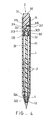
- the automatic pencil includes an elongated tube 1 having an upper open end 11, a tapered lower end 12, and a central bore 13 formed therein.
- a plurality of leads 2 (see Fig. 2) are received in the elongated tube 1.
- a guiding ring 4 is mounted in the elongated tube 1 near the lower end 12 of the elongated tube 1 to prevent the leads from moving toward the upper end 11 of the elongated tube 1.
- a propelling mechanism 3 is mounted to the elongated tube 1 to force the leads 2 to enter and pass through the guiding ring 4 to protrude from the lower end 12 of the elongated tube 1 for writing purposes, in a manner that will be described later.
- the elongated tube 1 has a plurality of positioning grooves 14 of a predetermined length axially formed around an inner surface thereof near the upper open end 11.
- the central bore 13 of the elongated tube 1 has an upper section 131 and a lower section 132 the diameter of the lower section 132 being smaller than that of the upper section 131, so that a shoulder portion 133 is formed below the positioning grooves 14.
- the lower section 132 has a lower end 134 adjacent to the guiding ring 4, and a plurality of receiving grooves 15 radially extending from the lower section 132 for receiving the leads 2, as best illustrated in Fig. 3.
- Each of the receiving grooves 15 is correspondingly aligned with the respective positioning groove 14 and has an upper end communicating with the upper section 131 and a lower end bounded by an inclined inner face 151 of the elongated tube 1.
- the inclined inner face 151 converges toward the lower end 134 of the lower section 132.
- the propelling mechanism 3 includes an elongated cylinder 31 with an upper end 311 and a lower end 322 slidably mounted to the upper end 11 of the elongated tube 1, and a push rod 32 slidably fitted in the lower section 132, so that the leads 2 can be confined in the receiving grooves 15 in such a manner that the butt end of one lead is in series in contact with the sharp end of the one behind it, as shown in Figs 2 and 3.
- the push rod 32 has a diametrical cross projection 321 formed at the upper end 320, thereof and the lower end 312 of the elongated cylinder 31 has a cavity 313 formed therein.
- the cavity 313 has a recess portion 314 formed at its innermost end so that the upper end 320 and the diametrical cross projection 321 of the push rod 32 can be detachably fitted into the cavity 313 and the recess portion 314 of the elongated cylinder 31 respectively, thus enabling the push rod 32 to be rotated by turning the elongated cylinder 31.
- the lower end of the push rod 32 extends to the lower end 134 of the lower section 132 of the elongated tube 1.
- the push rod 32 has a slot 324 axially extending from the lower end 322 thereof.
- the slot 324 of the push rod 32 cooperates with any one of the receiving grooves 15 to define a passage which allows the leads 2 in said one of the receiving grooves 15 to enter the guiding ring 4 one at a time, so that the leads 2 in the guiding ring 4 can be pushed to protrude from the lower end 12 of the elongated tube 1 by depressing the elongated cylinder 31, as best illustrated in Fig. 4.
- the elongated cylinder 31 has a mounting hole 315 radially formed therein.
- the mounting hole 315 has a spring 316 and a ball 317 biased by the spring 316 so as to engage with any one of the positioning grooves 14, allowing the elongated cylinder 31 to move between a first position where the upper end 311 of the elongated cylinder 31 is protruded from the upper end of the elongated tube with the ball 317 partially engaged with the upper end of one of the positioning grooves 14, as shown in Fig. 2, and a second position where the push rod 32 pushes the leads 2 into the guiding ring 4 so that that lead protrudes from the lower end 12 of the elongated tube 1, as best illustrated in Fig. 4.
- a coil spring 33 is sleeved around the push rod 31 and has one end portion 331 inserted into a retaining hole 323 formed near the upper end 320 of the push rod 31.
- the coil spring 33 is disposed between the lower end 312 of the elongated cylinder 31 and the shoulder portion 133 of the elongated tube 1 so as to force the elongated cylinder 31 to rest in the first position and force the upper end 320 of the push rod 32 to abut the lower end 312 of the elongated cylinder 31.
- the slot 324 of the push rod 32 may be rotated to communicate with an adjacent receiving groove 15 of the elongated tube 1 by manually rotating the elongated cylinder 31 several degrees from one to another of the positioning grooves 14 and the leads 2 in the receiving grooves can in turn enter the guiding ring 4 and be pushed to protrude from the lower end 12 of the elongated tube 1 when the elongated cylinder 31 is depressed to the second position.
- a axial first marking line 318 is provided on the outer face of the elongated cylinder 31 near the upper end 311.
- a plurality of second marking lines 17 is provided on the outer face of the elongated tube 1 near its upper end 11, which are correspondingly aligned with the positioning grooves 14 in the elongated tube 1.
- a user can thereby ensure the ball 317 is positively engaged with one of the positioning grooves 14 by aligning the first marking line 318 with one of the second marking lines 17.
- many spear leads 2 can be received in the receiving grooves 15 of the automatic pencil of this invention, rendering frequent supplying of the leads unnecessary.
- the elongated cylinder 31 is detached from the push rod 32 and removed from the elongated tube 1 by a force larger than that exerted by the coil spring 33, said larger force being sufficient to disengage the ball 317 from the positioning grooves 14.
- the push rod 32 is not removed as a result of its detachable seating in the elongated cylinder. Therefore, the leads supplied to the receiving grooves 15 will not be dropped into the second section 132 of the central bore 13 but arranged orderly in a stack with the tip of one lead abutting the base of the next.
Landscapes
- Mechanical Pencils And Projecting And Retracting Systems Therefor, And Multi-System Writing Instruments (AREA)
Priority Applications (1)
| Application Number | Priority Date | Filing Date | Title |
|---|---|---|---|
| EP90305130A EP0455902A1 (de) | 1990-05-11 | 1990-05-11 | Verbesserter automatischer Bleistift |
Applications Claiming Priority (1)
| Application Number | Priority Date | Filing Date | Title |
|---|---|---|---|
| EP90305130A EP0455902A1 (de) | 1990-05-11 | 1990-05-11 | Verbesserter automatischer Bleistift |
Publications (1)
| Publication Number | Publication Date |
|---|---|
| EP0455902A1 true EP0455902A1 (de) | 1991-11-13 |
Family
ID=8205418
Family Applications (1)
| Application Number | Title | Priority Date | Filing Date |
|---|---|---|---|
| EP90305130A Withdrawn EP0455902A1 (de) | 1990-05-11 | 1990-05-11 | Verbesserter automatischer Bleistift |
Country Status (1)
| Country | Link |
|---|---|
| EP (1) | EP0455902A1 (de) |
Citations (5)
| Publication number | Priority date | Publication date | Assignee | Title |
|---|---|---|---|---|
| GB144515A (en) * | 1919-08-21 | 1920-06-17 | Andrew Valeggia | Improvements in pencil-holders |
| US2219769A (en) * | 1939-01-10 | 1940-10-29 | Robert S Dorfman | Mechanical pencil |
| LU48571A1 (de) * | 1965-03-03 | 1965-07-12 | ||
| US4915521A (en) * | 1987-09-25 | 1990-04-10 | Saint Island International Patent And Law Offices | Mechanical pencil with rotary discharge member |
| US4944622A (en) * | 1989-03-16 | 1990-07-31 | Sheu Tyng Jen | Writing implement |
-
1990
- 1990-05-11 EP EP90305130A patent/EP0455902A1/de not_active Withdrawn
Patent Citations (5)
| Publication number | Priority date | Publication date | Assignee | Title |
|---|---|---|---|---|
| GB144515A (en) * | 1919-08-21 | 1920-06-17 | Andrew Valeggia | Improvements in pencil-holders |
| US2219769A (en) * | 1939-01-10 | 1940-10-29 | Robert S Dorfman | Mechanical pencil |
| LU48571A1 (de) * | 1965-03-03 | 1965-07-12 | ||
| US4915521A (en) * | 1987-09-25 | 1990-04-10 | Saint Island International Patent And Law Offices | Mechanical pencil with rotary discharge member |
| US4944622A (en) * | 1989-03-16 | 1990-07-31 | Sheu Tyng Jen | Writing implement |
Similar Documents
| Publication | Publication Date | Title |
|---|---|---|
| US6601483B2 (en) | Automatic bit changing screwdriver | |
| US5325745A (en) | Screwdriver | |
| EP0311121A1 (de) | Schreibgerät | |
| US2736562A (en) | Interchangeable drill | |
| US6517272B1 (en) | Double-chuck mechanical pencil | |
| US4973179A (en) | Clip actuated latch mechanism for retractable writing instruments | |
| US4377349A (en) | Ball point pen | |
| KR970003363Y1 (ko) | 복합필기구 | |
| US4480668A (en) | Screw driver kit | |
| US20020085874A1 (en) | Composite holding device | |
| EP0378724A1 (de) | Mehrfachschreibgerät | |
| US4948285A (en) | Ball point pen with two cartridges | |
| US4955739A (en) | Mechanical pencil having side push button actuated lead advance | |
| US2219769A (en) | Mechanical pencil | |
| US4515492A (en) | Writing implement and kit | |
| US6322267B1 (en) | Adjustable crayon holder | |
| EP0709233B1 (de) | Gleitkörper für einen Füllminenstift | |
| CA2017686A1 (en) | Automatic pencil | |
| US6254296B1 (en) | Automatic pencil structure | |
| US2690736A (en) | Mechanical pencil employing clip in assembly | |
| US11305576B2 (en) | Multi pen dry erase marker | |
| US3019768A (en) | Connector means for a tandem writing unit | |
| US4944622A (en) | Writing implement | |
| US2130230A (en) | Mechanically operated magazine pencil | |
| US5882132A (en) | Side knock-type mechanical pencil |
Legal Events
| Date | Code | Title | Description |
|---|---|---|---|
| PUAI | Public reference made under article 153(3) epc to a published international application that has entered the european phase |
Free format text: ORIGINAL CODE: 0009012 |
|
| AK | Designated contracting states |
Kind code of ref document: A1 Designated state(s): AT BE CH DE DK ES FR GB GR IT LI LU NL SE |
|
| STAA | Information on the status of an ep patent application or granted ep patent |
Free format text: STATUS: THE APPLICATION IS DEEMED TO BE WITHDRAWN |
|
| 18D | Application deemed to be withdrawn |
Effective date: 19920514 |