EP0455932B1 - Appareil de mesure de la position ou de la vitesse d'une pièce mobile au moins partiellement ferromagnétique - Google Patents
Appareil de mesure de la position ou de la vitesse d'une pièce mobile au moins partiellement ferromagnétique Download PDFInfo
- Publication number
- EP0455932B1 EP0455932B1 EP19910100930 EP91100930A EP0455932B1 EP 0455932 B1 EP0455932 B1 EP 0455932B1 EP 19910100930 EP19910100930 EP 19910100930 EP 91100930 A EP91100930 A EP 91100930A EP 0455932 B1 EP0455932 B1 EP 0455932B1
- Authority
- EP
- European Patent Office
- Prior art keywords
- measuring
- magnetic
- coils
- movable body
- core
- Prior art date
- Legal status (The legal status is an assumption and is not a legal conclusion. Google has not performed a legal analysis and makes no representation as to the accuracy of the status listed.)
- Expired - Lifetime
Links
Images

Classifications
-
- G—PHYSICS
- G01—MEASURING; TESTING
- G01P—MEASURING LINEAR OR ANGULAR SPEED, ACCELERATION, DECELERATION, OR SHOCK; INDICATING PRESENCE, ABSENCE, OR DIRECTION, OF MOVEMENT
- G01P3/00—Measuring linear or angular speed; Measuring differences of linear or angular speeds
- G01P3/42—Devices characterised by the use of electric or magnetic means
- G01P3/44—Devices characterised by the use of electric or magnetic means for measuring angular speed
- G01P3/48—Devices characterised by the use of electric or magnetic means for measuring angular speed by measuring frequency of generated current or voltage
- G01P3/481—Devices characterised by the use of electric or magnetic means for measuring angular speed by measuring frequency of generated current or voltage of pulse signals
- G01P3/488—Devices characterised by the use of electric or magnetic means for measuring angular speed by measuring frequency of generated current or voltage of pulse signals delivered by variable reluctance detectors
Definitions
- the invention relates to an arrangement for position detection or for speed measurement of an at least partially magnetic and toothed movable body according to the preamble of claim 1.
- Such arrangements can be used, for example, in automotive engines, transmissions or braking systems to measure the speed of a rotating body part, e.g. a gear.
- An arrangement for position detection or for speed measurement according to the preamble of claim 1 is known from DE-A-1 523 191, where a sensor provided with an E-shaped magnetic core is used in a method and a device for the remote display of a rotational speed or one Angle of rotation of a rotating toothed disc, which consists of two cap-like disc halves.
- the speeds can also be recorded when the two disc halves are at a standstill.
- a single excitation winding excited by an alternating current is arranged on the middle leg of the magnetic core and a measuring winding is arranged on each of the two outer legs.
- the two measuring windings are connected to one another in a differential circuit. In operation, several teeth of the toothed disk are temporarily located in the front of each of two air gaps in the magnetic core.
- the invention has for its object to provide an arrangement for position detection or for speed measurement of at least partially magnetic bodies, which is pre-economical and without great effort while avoiding the use of semiconductor components and permanent magnets can be produced and with which even very low speeds, including zero speed, can be detected or measured with great efficiency.
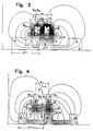
- FIGS. 1 to 4 each show, inter alia, a cross section of part of the gear 1 running perpendicular to the axis of rotation of the gear 1, it being assumed that the cross section of the teeth 2 is preferably trapezoidal.
- FIGS. 1 to 4 there is at least one core 4 or 4a; 4b provided with an air gap 3, on which coils 5, 6, 7 and 8 are arranged.
- the coils 5 to 8 consist of at least two measuring coils 5 and 6 and two excitation coils 7 and 8.
- the direction of movement of the teeth 2 of the gear 1 and thus the direction of movement of the movable body is parallel or tangential to an outer side of the air gap 3.
- a ferromagnetic Part of the movable body, namely the teeth 2 of the gear 1, is located at least temporarily in the front of the air gap 3 during its movement.
- the two excitation coils 7 and 8 are fed by at least one alternating current i during operation to generate two magnetic fluxes ⁇ 1 and ⁇ 2, which each generate a voltage at the output of the two measuring coils 5 and 6 by means of magnetic induction, which is denoted by u 1 and u 2 in FIGS.
- a measuring coil combination 5; 6 the turns of the two measuring coils 5 and 6 are each connected in series so that a voltage u is present at the output of the measuring coil combination 5; 6, which is equal to the difference between the two by the magnetic fluxes ⁇ 1 and ⁇ 2 is 5 or 6 induced voltages in the individual measuring coils.
- the core 4 or 4a; 4b and the two Excitation coils 7 and 8 are each designed, arranged and dimensioned such that the two magnetic fluxes im1 and ⁇ 2 in operation are present in at least partial absence in front of the air gap 3 of the ferromagnetic part of the movable body, ie in the absence of teeth 2 of gear 1, approximately are the same size.
- the core 4 or 4a; 4b each has at least two ferromagnetic core parts which are arranged spatially separated.
- the two excitation coils 7 and 8 are then each arranged on one of the two ferromagnetic core parts for the purpose of generating one of the two magnetic fluxes ⁇ 1 and ⁇ 2 in the latter.
- One of the two measuring coils 5 and 6 is assigned to each of the two ferromagnetic core parts and the windings of the two measuring coils 5 and 6 are each arranged on the ferromagnetic core part assigned to the respective measuring coil 5 and 6.
- the core 4 each has two magnetic circuits ABCD and EBCF and a central web BC common to the two magnetic circuits ABCD and EBCF. 3, the three points F, C and D coincide and form a single point F; C; D.
- the two magnetic circuits ABCD and EBCF each represent the above-mentioned two spatially separated ferromagnetic core parts in the two variants.
- the two measuring coils 5 and 6 and the two excitation coils 7 and 8 are each outside the central web BC on one of the two magnetic circuits ABCD or EBCF arranged.
- the two measuring coils 5 and 6 are in each case electrically connected in series in such a way that a voltage u is present at the output of the series connection of the two measuring coils 5 and 6, which is equal to the difference u1-u2 of the two by the magnetic fluxes ⁇ 1 and ⁇ 2 in the individual measuring coils 5 and 6 induced voltages u1 and u2.
- the magnetic fluxes ⁇ 1 and ⁇ 2 flowing in the two magnetic circuits ABCD and EBCF also have the same sense of direction in the common central web BC, so that a total magnetic flux ⁇ 1 + ⁇ 2 flows there.
- the excitation coils 7 and 8 are each arranged as close as possible to the air gap 3 or 9 on their magnetic circuit ABCD or EBCF.
- the two air gaps 3 and 9 are arranged on the magnetic circuit ABCD or EBCF outside of the common central web BC and the ferromagnetic part of the movable body, i. H. the teeth 2 of the gear 1 is only in the front of one of the two air gaps 3 and 9, namely z. B. in the front of the air gap 3.
- the direction of movement of the movable body, d. H. of the gear 1, in this case runs only parallel or tangential to an outer side of a single one of the two air gaps 3 and 9, namely the air gap 3.
- the two air gaps 3 and 9 are arranged outside the common central web BC in their magnetic circuit ABCD or EBCF in such a way that outer sides of at least the two air gaps 3 and 9 are the same, in the illustration of FIG Horizontal plane.
- the moving direction of the movable body, i.e. H. of the gear 1 then runs parallel or tangential to the plane and a ferromagnetic part of the movable body, namely the teeth 2 of the gear 1, is alternately in the front of each of the two air gaps 3 and 9.
- the direction of movement of the movable body runs in this case parallel or tangential to an outer side of each of the two air gaps 3 and 9.
- the center bar BC preferably has a symmetry surface in the two variants, and the two magnetic circuits ABCD and EBCF are then preferably formed symmetrically to the symmetry surface of the center bar BC.
- the core 4 used in the second variant then preferably has an E-shaped cross section, as shown in FIG. 3. Otherwise corresponds to the sub-variant shown in FIG. 3 the second variant shown in FIG. 2.
- the core 4a; 4b consists of two separate lower cores 4a and 4b, which are arranged surface-symmetrically to one another.
- the symmetry surface is designated by S in FIG. 4. 4 it was assumed that the two lower cores 4a and 4b are rod-shaped and of the same length. They are then parallel and their ends are preferably arranged flush with one another.
- the lower cores 4a and 4b represent the two ferromagnetic core parts mentioned above, both a first and a second end of the two lower cores 4a and 4b being separated from one another by an air gap 3 and 9, respectively.
- the direction of movement of the movable body is preferably parallel or tangential to a narrow side of the lower cores 4a and 4b.
- the two measuring coils 5 and 6 are connected to each other to form a measuring coil combination 5; 6 in such a way that alternately one turn of one measuring coil 5 is connected in series with one turn of the other measuring coil 6 in such a way that the direction of the magnetic fluxes ⁇ 1 and ⁇ 2 in the Both lower cores 4a and 4b and the winding direction of the turns of the individual measuring coils 5 and 6 around the associated lower core 4a and 4b are each selected so that the voltages induced by the two magnetic fluxes ⁇ 1 and ⁇ 2 in the turns of the measuring coils 5 and 6 have an opposite sense of direction in the two measuring coils 5 and 6, so that only the difference between the two magnetic fluxes ⁇ 1 and ⁇ 2 at the output of the measuring coil combination 5; 6 is effective as voltage u.
- the turns of the measuring coils 5 and 6 preferably have an opposite turn sense.
- the two magnetic fluxes ⁇ 1 and ⁇ 2 can also have an opposite parallel direction.
- the turns of the turns of the measuring coils 5 and 6 should preferably be selected in the same direction.
- the two excitation coils 7 and 8 are preferably approximately the same, are electrically connected in series and, in operation, are fed by a single alternating current i, that of an alternating current source 10 (see Figures 1 and 2) is supplied, which in turn is connected to the series connection of the two excitation coils 7 and 8.
- a tooth period L of the gear 1 is to be chosen so large that when a tooth 2 of the gear 1 is in the front of one of the two air gaps 3 or 9, no other tooth 2 of the gear 1 is located located in the front of the other of the two air gaps 9 or 3.
- the tooth period L of the gear 1 is to be selected to be greater than or equal to twice the center distance a of the two outer webs of the core 4 provided with an E-shaped cross section or of the two lower cores 4a and 4b.
- the second variant and the arrangement according to the invention can be twice as efficient as the first variant.
- the distance d preferably has a value of 0.1 to 3 mm.
- the other air gap 9 and 3 remains unchanged, so that greatly different magnetic fluxes fladore1 and ⁇ 2 flow, which in Figures 3 and 4 by the number of field lines of the respective Magnetic flux ⁇ 1 or ⁇ 2 is shown symbolically. This results in a relatively large magnetic flux difference ⁇ 1- ⁇ 2, which can be measured by means of the measuring coil combination 5; 6 and a voltmeter connected to it as an alternating voltage u of constant amplitude.
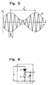
- the alternating voltage u (see FIG. 5) only represents a higher-frequency carrier signal 11, the frequency of which is f h and the amplitude of which is modulated by the rotational movement of the gear 1.
- the frequency f n of a low-frequency modulation signal 12 generated in this way is proportional to the speed of the gear 1 and can be determined by means of a detector.
- the amplitude signal modulated by means of the modulation signal 12 is shown in FIG. 5 as a function of the time t.
- An evaluation device (not shown in FIGS. 1 to 4), which is either a voltmeter or a detector, must therefore be connected to the measuring coil combination 5; 6.
- a structure of the latter can be seen in FIG. 6.
- the known detector shown there consists of the series circuit D; R; C of a diode D and an RC parallel circuit R; C.
- the latter consists of a resistor R and a capacitor C, both of which are connected in parallel.
- the output voltage u of the measuring coil combination 5; 6 feeds the input of the detector, which is formed by the two poles of the series circuit D; R; C, while the output of the detector is formed by the two poles of the RC parallel circuit R; C.
Landscapes
- Physics & Mathematics (AREA)
- General Physics & Mathematics (AREA)
- Measurement Of Length, Angles, Or The Like Using Electric Or Magnetic Means (AREA)
- Transmission And Conversion Of Sensor Element Output (AREA)
Claims (6)
- Dispositif pour détecter la position ou mesurer la vitesse d'un corps mobile (1), au moins partiellement magnétique et équipé de dents (2), et comportant un noyau (4 ou 4a; 4b) équipé d'au moins deux entrefers (3, 9) et sur lequel sont situées une première bobine d'excitation (7 ou 8) alimentée en fonctionnement par un courant alternatif (i), et deux bobines de mesure (5, 6), et dans lequel le noyau (4 ou 4a; 4b) comporte au moins deux parties magnétiques, dans lesquelles en fonctionnement un flux magnétiques respectif (Φ1 et Φ2) est produit par un courant alternatif, et dans lequel une partie magnétique du corps mobile (1) est située au moins par instants en face de l'un des entrefers (3, 9), et à chacune des deux parties magnétiques du noyau est associée l'une des deux bobines de mesure (5, 6), dont les spires sont disposées respectivement sur la partie magnétique du noyau, qui est associée à la bobine de mesure respective (5 ou 6), et dans lequel pour la formation d'un ensemble combiné de bobines de mesure (5; 6), les spires des deux bobines (5, 6) de mesure sont reliées entre elles en série de sorte que, pendant le fonctionnement, à la sortie de l'ensemble combiné de bobines de mesure (5; 6) est présente une tension (u), qui est égale à la différence de deux tensions induites par les flux magnétiques (Φ1, Φ2) dans les différentes bobines de mesure (5 ou 6), et dans lequel le noyau (4 ou 4a; 4b) est agencé et dimensionné de telle sorte qu'en fonctionnement, les deux flux magnétiques (Φ1, Φ2) sont approximativement égaux pendant l'absence au moins partielle de la partie magnétique du corps mobile (1), caractérisé en ce que la partie magnétique du corps mobile (1) et les parties magnétiques du noyau (4 ou 4a; 4b) sont ferromagnétiques, qu'il est prévu une seconde bobine d'excitation (8 ou 7) alimentée en fonctionnement par un courant alternatif, que les première et seconde bobines d'excitation (7, 8) sont disposées chacune sur l'une des deux parties ferromagnétiques du noyau, dans lesquelles elles produisent, en fonctionnement, respectivement l'un des deux flux magnétiques (Φ1, Φ2) à l'aide d'un courant alternatif, que les première et seconde bobines d'excitation (7, 8) sont agencées, disposées et dimensionnées de telle sorte que les deux flux magnétiques (Φ1, Φ2), qui sont présents en fonctionnement, sont approximativement égaux, pendant l'absence au moins partielle de la partie ferromagnétique du corps mobile (1), et que le noyau (4a; 4b) est constitué de deux noyaux partiels séparés (4a, 4b), qui sont disposés avec des surfaces réciproquement symétriques et qui représentent les deux parties ferromagnétiques du noyau, auquel cas respectivement aussi bien une première extrémité qu'une seconde extrémité des deux noyaux partiels (4a, 4b) sont séparées l'une de l'autre par un entrefer respectif (3, 9), que les deux bobines de mesure (5, 6) sont reliées entre elles de telle sorte qu'alternativement une spire d'une bobine de mesure (5) est branchée en série avec une spire de l'autre bobine de mesure (6) et ce de telle sorte que le sens des flux magnétiques (Φ₁, Φ₂) dans les deux noyaux partiels (4a, 4b) ainsi que le sens d'enroulement des spires des différentes bobines de mesure (5, 6) autour des noyaux partiels (4a ou 4b) qui leur sont associés, sont choisis respectivement de telle sorte que les tensions, qui sont induites par les deux flux magnétiques (Φ₁, Φ₂) dans les spires des bobines de mesure (5, 6) ont des sens opposés de sorte que seule la différence des deux flux magnétiques (Φ₁, Φ₂) agit à la sortie de l'ensemble combiné de bobines de mesure (5; 6).
- Dispositif suivant la revendication 1, caractérisé par le fait que les deux noyaux partiels (4a, 4b) sont réalisés en forme de barreaux et sont parallèles.
- Dispositif selon la revendication 1 ou 2, caractérisé en ce qu'une direction de déplacement du corps mobile (1) est parallèle ou tangentielle à un petit côté des noyaux partiels (4a, 4b).
- Dispositif selon l'une des revendications 1 à 3, caractérisé en ce que les deux bobines d'excitation (7, 8) sont approximativement identiques, sont branchées électriquement en série et sont alimentées, en fonctionnement, par un seul courant alternatif (i).
- Dispositif selon l'une des revendications 1 à 4, caractérisé en ce qu'un appareil d'évaluation est raccordé à l'ensemble combiné de bobines de mesure (5; 6).
- Dispositif selon la revendication 5, caractérisé en ce que l'appareil d'évaluation est un voltmètre ou un détecteur.
Applications Claiming Priority (2)
| Application Number | Priority Date | Filing Date | Title |
|---|---|---|---|
| CH157290 | 1990-05-09 | ||
| CH1572/90 | 1990-05-09 |
Publications (2)
| Publication Number | Publication Date |
|---|---|
| EP0455932A1 EP0455932A1 (fr) | 1991-11-13 |
| EP0455932B1 true EP0455932B1 (fr) | 1994-07-20 |
Family
ID=4213564
Family Applications (1)
| Application Number | Title | Priority Date | Filing Date |
|---|---|---|---|
| EP19910100930 Expired - Lifetime EP0455932B1 (fr) | 1990-05-09 | 1991-01-25 | Appareil de mesure de la position ou de la vitesse d'une pièce mobile au moins partiellement ferromagnétique |
Country Status (3)
| Country | Link |
|---|---|
| EP (1) | EP0455932B1 (fr) |
| JP (1) | JPH04230864A (fr) |
| DE (1) | DE59102221D1 (fr) |
Family Cites Families (5)
| Publication number | Priority date | Publication date | Assignee | Title |
|---|---|---|---|---|
| GB800504A (en) * | 1952-01-12 | 1958-08-27 | Athelstan Bodley Scott | Electro-magnetic apparatus for the determination of mechanical stresses or movements |
| US2807014A (en) * | 1955-08-09 | 1957-09-17 | Royce J Rickert | Zero speed detector |
| DE1523191A1 (de) * | 1965-02-23 | 1969-09-18 | Inst Regelungstechnik | Verfahren und Vorrichtung zur Fernanzeige einer Drehgeschwindigkeit oder eines Drehwinkels |
| US3559064A (en) * | 1968-04-25 | 1971-01-26 | Westinghouse Air Brake Co | Velocity indication device with zero speed detection capability |
| US3961214A (en) * | 1975-06-18 | 1976-06-01 | International Telephone & Telegram Corporation | Velocity pick-off with noise cancellation |
-
1991
- 1991-01-25 DE DE59102221T patent/DE59102221D1/de not_active Expired - Fee Related
- 1991-01-25 EP EP19910100930 patent/EP0455932B1/fr not_active Expired - Lifetime
- 1991-05-02 JP JP10024891A patent/JPH04230864A/ja active Pending
Also Published As
| Publication number | Publication date |
|---|---|
| EP0455932A1 (fr) | 1991-11-13 |
| DE59102221D1 (de) | 1994-08-25 |
| JPH04230864A (ja) | 1992-08-19 |
Similar Documents
| Publication | Publication Date | Title |
|---|---|---|
| DE69925573T2 (de) | Magnetischer F?hler hergestellt auf einem halbleitenden Substrat | |
| DE69423867T2 (de) | Gleichstromsensor | |
| DE3411773C2 (de) | Vorrichtung zur Erfassung der Drehzahl und/oder eines Drehwinkels einer Welle | |
| DE3635207C2 (fr) | ||
| DE69207223T2 (de) | Vorrichtung zum Messen von Strömen | |
| EP0334854B1 (fr) | Dispositif de mesure d'une rotation angulaire et ou d'une vitesse de rotation | |
| DE2446132A1 (de) | Winkelgeschwindigkeitssensor | |
| DE3515350C2 (fr) | ||
| DE69019491T2 (de) | Verschiebungssensor vom Induktionstyp mit Unempfindlichkeit gegenüber externen magnetischen Feldern. | |
| DE69001888T2 (de) | Drehzahlmessaufnehmer mit veraenderlichem magnetischem flusswiderstand. | |
| EP0065762B1 (fr) | Méthode et arrangement de circuit pour mesurer un champ magnétique, spécialement le champ magnétique terrestre | |
| DE2332110C3 (de) | Berührungsfreies Meßsystem zur Leistungsmessung | |
| DE3326477A1 (de) | Anordnung zur bestimmung der drehzahl, der drehrichtung und/oder des drehwinkels eines gegenstandes | |
| DE2829264C2 (fr) | ||
| DE2916289C2 (de) | Messung der Magnetflußänderung und der LuftspaltgröBe eines Luftspaltes zwischen einem Elektromagneten und einem ferromagnetischen Material | |
| DE4425903A1 (de) | Vorrichtung mit einem Meßtransformator zur Erfassung der Position eines linear beweglichen Objektes | |
| DE2541538B2 (de) | Geschwindigkeitsfühleinrichtung für ein Rad | |
| EP0455932B1 (fr) | Appareil de mesure de la position ou de la vitesse d'une pièce mobile au moins partiellement ferromagnétique | |
| DE3147819C2 (fr) | ||
| DE3628585A1 (de) | Impulsdrehzahlgeber | |
| DE19618114A1 (de) | Stromkompensierter Stromsensor | |
| DE3705450A1 (de) | Stromwandler zur messung von rechteckstroemen nach dem kompensationsprinzip | |
| DE1523221C3 (de) | Kontaktloses GeschwindigkeitsmeBwerk | |
| DE69209648T2 (de) | Verfahren und Vorrichtung zur Messung des Abstandes zwischen zwei gegenüberliegenden Oberflächen mittels eines Reluktanzverfahrens | |
| AT326184B (de) | Anordnung zum berührungsfreien messen des lotrechten abstandes zwischen einem elektromagneten und einer ankerschiene eines elektromagnetischen trag- oder führungssystems |
Legal Events
| Date | Code | Title | Description |
|---|---|---|---|
| PUAI | Public reference made under article 153(3) epc to a published international application that has entered the european phase |
Free format text: ORIGINAL CODE: 0009012 |
|
| AK | Designated contracting states |
Kind code of ref document: A1 Designated state(s): CH DE FR GB IT LI |
|
| 17P | Request for examination filed |
Effective date: 19911129 |
|
| RAP1 | Party data changed (applicant data changed or rights of an application transferred) |
Owner name: LANDIS & GYR BUSINESS SUPPORT AG |
|
| 17Q | First examination report despatched |
Effective date: 19930510 |
|
| GRAA | (expected) grant |
Free format text: ORIGINAL CODE: 0009210 |
|
| AK | Designated contracting states |
Kind code of ref document: B1 Designated state(s): CH DE FR GB IT LI |
|
| GBT | Gb: translation of ep patent filed (gb section 77(6)(a)/1977) |
Effective date: 19940725 |
|
| REF | Corresponds to: |
Ref document number: 59102221 Country of ref document: DE Date of ref document: 19940825 |
|
| ET | Fr: translation filed | ||
| ITF | It: translation for a ep patent filed | ||
| RAP2 | Party data changed (patent owner data changed or rights of a patent transferred) |
Owner name: LANDIS & GYR TECHNOLOGY INNOVATION AG |
|
| PLBE | No opposition filed within time limit |
Free format text: ORIGINAL CODE: 0009261 |
|
| STAA | Information on the status of an ep patent application or granted ep patent |
Free format text: STATUS: NO OPPOSITION FILED WITHIN TIME LIMIT |
|
| 26N | No opposition filed | ||
| PGFP | Annual fee paid to national office [announced via postgrant information from national office to epo] |
Ref country code: FR Payment date: 19970117 Year of fee payment: 7 |
|
| PGFP | Annual fee paid to national office [announced via postgrant information from national office to epo] |
Ref country code: DE Payment date: 19970305 Year of fee payment: 7 |
|
| PGFP | Annual fee paid to national office [announced via postgrant information from national office to epo] |
Ref country code: CH Payment date: 19970414 Year of fee payment: 7 |
|
| PGFP | Annual fee paid to national office [announced via postgrant information from national office to epo] |
Ref country code: GB Payment date: 19971218 Year of fee payment: 8 |
|
| PG25 | Lapsed in a contracting state [announced via postgrant information from national office to epo] |
Ref country code: LI Free format text: LAPSE BECAUSE OF NON-PAYMENT OF DUE FEES Effective date: 19980131 Ref country code: FR Free format text: THE PATENT HAS BEEN ANNULLED BY A DECISION OF A NATIONAL AUTHORITY Effective date: 19980131 Ref country code: CH Free format text: LAPSE BECAUSE OF NON-PAYMENT OF DUE FEES Effective date: 19980131 |
|
| REG | Reference to a national code |
Ref country code: CH Ref legal event code: PL |
|
| REG | Reference to a national code |
Ref country code: FR Ref legal event code: ST |
|
| PG25 | Lapsed in a contracting state [announced via postgrant information from national office to epo] |
Ref country code: DE Free format text: LAPSE BECAUSE OF NON-PAYMENT OF DUE FEES Effective date: 19981103 |
|
| PG25 | Lapsed in a contracting state [announced via postgrant information from national office to epo] |
Ref country code: GB Free format text: LAPSE BECAUSE OF NON-PAYMENT OF DUE FEES Effective date: 19990125 |
|
| GBPC | Gb: european patent ceased through non-payment of renewal fee |
Effective date: 19990125 |
|
| PG25 | Lapsed in a contracting state [announced via postgrant information from national office to epo] |
Ref country code: IT Free format text: LAPSE BECAUSE OF NON-PAYMENT OF DUE FEES;WARNING: LAPSES OF ITALIAN PATENTS WITH EFFECTIVE DATE BEFORE 2007 MAY HAVE OCCURRED AT ANY TIME BEFORE 2007. THE CORRECT EFFECTIVE DATE MAY BE DIFFERENT FROM THE ONE RECORDED. Effective date: 20050125 |