EP0455948A1 - Procédé et appareil de séparation de matériaux, en particulier faiblement magnétisables, à partir d'un mélange de solides - Google Patents
Procédé et appareil de séparation de matériaux, en particulier faiblement magnétisables, à partir d'un mélange de solides Download PDFInfo
- Publication number
- EP0455948A1 EP0455948A1 EP91103362A EP91103362A EP0455948A1 EP 0455948 A1 EP0455948 A1 EP 0455948A1 EP 91103362 A EP91103362 A EP 91103362A EP 91103362 A EP91103362 A EP 91103362A EP 0455948 A1 EP0455948 A1 EP 0455948A1
- Authority
- EP
- European Patent Office
- Prior art keywords
- magnetic field
- slideway
- conveyor belt
- solid mixture
- magnetizable
- Prior art date
- Legal status (The legal status is an assumption and is not a legal conclusion. Google has not performed a legal analysis and makes no representation as to the accuracy of the status listed.)
- Withdrawn
Links
- 239000000463 material Substances 0.000 title claims abstract description 39
- 238000000034 method Methods 0.000 title claims abstract description 11
- 239000000203 mixture Substances 0.000 title claims abstract description 6
- 239000007787 solid Substances 0.000 title claims abstract description 4
- 238000000926 separation method Methods 0.000 title abstract description 6
- 230000005291 magnetic effect Effects 0.000 claims abstract description 74
- 239000008247 solid mixture Substances 0.000 claims description 30
- 238000011144 upstream manufacturing Methods 0.000 claims description 6
- 239000000470 constituent Substances 0.000 description 6
- XEEYBQQBJWHFJM-UHFFFAOYSA-N Iron Chemical compound [Fe] XEEYBQQBJWHFJM-UHFFFAOYSA-N 0.000 description 5
- 229910001220 stainless steel Inorganic materials 0.000 description 4
- 230000005294 ferromagnetic effect Effects 0.000 description 3
- PXHVJJICTQNCMI-UHFFFAOYSA-N Nickel Chemical compound [Ni] PXHVJJICTQNCMI-UHFFFAOYSA-N 0.000 description 2
- 239000000428 dust Substances 0.000 description 2
- 230000005484 gravity Effects 0.000 description 2
- 229910052742 iron Inorganic materials 0.000 description 2
- 239000011133 lead Substances 0.000 description 2
- 239000010935 stainless steel Substances 0.000 description 2
- 229910001369 Brass Inorganic materials 0.000 description 1
- RYGMFSIKBFXOCR-UHFFFAOYSA-N Copper Chemical compound [Cu] RYGMFSIKBFXOCR-UHFFFAOYSA-N 0.000 description 1
- 229910000990 Ni alloy Inorganic materials 0.000 description 1
- 238000006887 Ullmann reaction Methods 0.000 description 1
- HCHKCACWOHOZIP-UHFFFAOYSA-N Zinc Chemical compound [Zn] HCHKCACWOHOZIP-UHFFFAOYSA-N 0.000 description 1
- 229910045601 alloy Inorganic materials 0.000 description 1
- 239000000956 alloy Substances 0.000 description 1
- 239000010951 brass Substances 0.000 description 1
- 238000006243 chemical reaction Methods 0.000 description 1
- 229910052802 copper Inorganic materials 0.000 description 1
- 239000010949 copper Substances 0.000 description 1
- 230000000694 effects Effects 0.000 description 1
- 230000008030 elimination Effects 0.000 description 1
- 238000003379 elimination reaction Methods 0.000 description 1
- 239000011521 glass Substances 0.000 description 1
- 230000001771 impaired effect Effects 0.000 description 1
- 239000006148 magnetic separator Substances 0.000 description 1
- 238000004519 manufacturing process Methods 0.000 description 1
- 229910000734 martensite Inorganic materials 0.000 description 1
- 238000011089 mechanical engineering Methods 0.000 description 1
- 229910052759 nickel Inorganic materials 0.000 description 1
- 230000005298 paramagnetic effect Effects 0.000 description 1
- 239000004033 plastic Substances 0.000 description 1
- XLYOFNOQVPJJNP-UHFFFAOYSA-N water Substances O XLYOFNOQVPJJNP-UHFFFAOYSA-N 0.000 description 1
- 239000011701 zinc Substances 0.000 description 1
- 229910052725 zinc Inorganic materials 0.000 description 1
Images

Classifications
-
- B—PERFORMING OPERATIONS; TRANSPORTING
- B03—SEPARATION OF SOLID MATERIALS USING LIQUIDS OR USING PNEUMATIC TABLES OR JIGS; MAGNETIC OR ELECTROSTATIC SEPARATION OF SOLID MATERIALS FROM SOLID MATERIALS OR FLUIDS; SEPARATION BY HIGH-VOLTAGE ELECTRIC FIELDS
- B03C—MAGNETIC OR ELECTROSTATIC SEPARATION OF SOLID MATERIALS FROM SOLID MATERIALS OR FLUIDS; SEPARATION BY HIGH-VOLTAGE ELECTRIC FIELDS
- B03C1/00—Magnetic separation
- B03C1/02—Magnetic separation acting directly on the substance being separated
- B03C1/26—Magnetic separation acting directly on the substance being separated with free falling material
-
- B—PERFORMING OPERATIONS; TRANSPORTING
- B03—SEPARATION OF SOLID MATERIALS USING LIQUIDS OR USING PNEUMATIC TABLES OR JIGS; MAGNETIC OR ELECTROSTATIC SEPARATION OF SOLID MATERIALS FROM SOLID MATERIALS OR FLUIDS; SEPARATION BY HIGH-VOLTAGE ELECTRIC FIELDS
- B03C—MAGNETIC OR ELECTROSTATIC SEPARATION OF SOLID MATERIALS FROM SOLID MATERIALS OR FLUIDS; SEPARATION BY HIGH-VOLTAGE ELECTRIC FIELDS
- B03C1/00—Magnetic separation
- B03C1/02—Magnetic separation acting directly on the substance being separated
- B03C1/035—Open gradient magnetic separators, i.e. separators in which the gap is unobstructed, characterised by the configuration of the gap
-
- B—PERFORMING OPERATIONS; TRANSPORTING
- B03—SEPARATION OF SOLID MATERIALS USING LIQUIDS OR USING PNEUMATIC TABLES OR JIGS; MAGNETIC OR ELECTROSTATIC SEPARATION OF SOLID MATERIALS FROM SOLID MATERIALS OR FLUIDS; SEPARATION BY HIGH-VOLTAGE ELECTRIC FIELDS
- B03C—MAGNETIC OR ELECTROSTATIC SEPARATION OF SOLID MATERIALS FROM SOLID MATERIALS OR FLUIDS; SEPARATION BY HIGH-VOLTAGE ELECTRIC FIELDS
- B03C1/00—Magnetic separation
- B03C1/02—Magnetic separation acting directly on the substance being separated
- B03C1/16—Magnetic separation acting directly on the substance being separated with material carriers in the form of belts
- B03C1/22—Magnetic separation acting directly on the substance being separated with material carriers in the form of belts with non-movable magnets
Definitions
- the invention relates to a method and a device for separating magnetizable, in particular weakly magnetizable, materials from a solid mixture guided over a curved surface up to a discharge zone by means of a magnetic field.
- Magnetic roller separators to separate magnetisable constituents from a solid mixture also containing non-magnetisable constituents (cf. Ullmanns Encyklopadie der Technische Chemie, 4th edition, volume 2, pages 89 to 91).
- the mixture of solids is always fed from above onto a magnetic roller - also called magnetic tape roller or magnetic head roller - of the magnetic roller separator; the magnetic roller cutters thus work in the ejection process.
- the magnetic force must be so great that the iron is held against the components of gravity and centrifugal force up to a certain detachment point on the magnetic roller or a conveyor belt wrapping around the magnetic roller.
- Such magnetic rollers are frequently installed in the head station of conveyor belts and at the same time take on the function of the deflection and / or drive roller.
- the magnetic rollers consist of a smooth, fully magnetic roller with a rigid axis.
- the magnetic system inside extends over 360 o and rotates synchronously with the reel.
- the magnetic field can be generated by electromagnets or permanent magnets, electromagnets being operated exclusively with direct current.
- electromagnets being operated exclusively with direct current.
- This requires a very maintenance-intensive and heavily wearing power supply via slip rings, since the coils of the electromagnet are not fixed, but rotate together with the roller.
- the strongly inhomogeneous magnetic field generated by a magnetic roller is distributed over the entire circumference of the roller; therefore a correspondingly large magnet system or, in the case of electromagnets, a correspondingly large current requirement is necessary.
- the solid mixture to be separated is transported by means of the conveyor belt into the area of the head drum or magnetic roller and thus into the area of the magnetic field. While non-magnetizable constituents of the solid mixture remain unaffected by the magnetic field and are thrown onto a throwing parabola when the ejection line of the magnetic roller is reached, which depends mainly on the conveying speed and the diameter of the magnetic roller, the magnetizable components are held on the magnetic roller by the action of the magnetic field. At the earliest, they start to separate from an angle of 120 o , based on the vertical going through the axis of rotation of the magnetic roller and crossing the feed area. Often, however, the magnetisable components make a full rotation of the magnetic roller, and when it is wrapped around by a conveyor belt Magnetic rollers try to slide magnetizable parts that have not come off against the belt transport direction into the area of the strongest magnetic field.
- the invention has for its object to provide a method and an apparatus which allow in particular weakly magnetizable materials from a solid mixture also containing non-magnetizable parts to be separated without the disadvantages mentioned with reduced mechanical engineering effort and less susceptibility to failure.
- This object is achieved according to the invention by a method in that the effective area of the magnetic field is concentrated on the throw-off zone and the magnetic field, which is just detaching from the curved surface and merges into a throwing parabola, is forced through the magnetic field by a shorter throwing parabola compared to non-magnetizable materials.
- the invention thus takes a completely new path; the magnetizable constituents of the solid mixture are no longer held on the magnetic roller or the conveyor belt wrapping around a magnetic roller, as in the known magnetic roller separators, but are only influenced by the magnetic field when they have already detached from the curved surface and are on a trajectory or parabola .
- This magnetic field which is concentrated at the point in time after the material components have been detached from the curved surface, causes the magnetizable components to be attracted, and these pivot into a shorter throwing parabola than the non-magnetizable components which are not influenced by the magnetic field.
- the material throw-off zone is reached when the solid mixture to be separated is detached from the curved surface or preferably from a conveyor belt wrapping around the curved surface in order to pass into a throwing parabola.
- the forces of the magnetic field act as late as possible and specifically, namely when the materials are at the beginning of the flight phase and thereby cleanly separate the magnetizable components from the non-magnetizable components of the solid mixture, because the attractive forces of the magnetic field only shorten the parabola of the magnetizable ones Components; the throwing parabola of the non-magnetizable components remains unaffected.
- Permanent magnet or electromagnet systems can be used as magnet generators which, due to the active region concentrated according to the invention, either require or consume less magnetic mass - in the case of permanent magnets - or less energy - in the case of electromagnets.
- the magnetic field be supplied with a pre-classified solid mixture freed from highly magnetizable material components in a single-grain layer.
- a solid mixture with a limited grain size range is recommended. These can be sieved grain fractions, such as preferably in the range from 12 to 30 mm, 30 to 65 mm and 65 to 100 mm.
- the uniform grain fractions lead to approximately the same throwing parabolas, and since there are no highly magnetizable ones - such as iron, nickel and nickel alloys certain composition, ie materials with positive magnetic susceptibility, which are particularly strongly paramagnetic - components are no longer present, there are no separation problems due to components that may influence one another.
- the constituents to be separated from the solid mixture are primarily weakly magnetizable materials, such as, in particular, stainless steels, which are not inherently non-ferromagnetic due to possible alloy constituents or due to mechanical influences, e.g. due to the partial conversion of the austenitic structure to martensite during shredding in a shredder, have become sufficiently ferromagnetic.
- the solid mixture can also contain, for example, the components zinc, copper, brass and lead.
- a magnetic field generator can preferably be arranged next to a straight-line and / or curved and / or kinked slide valve made of an antimagnetic material in the region of the material discharge zone and its active region can be aligned with the discharge line.
- a stationary position of the magnetic field generator can be achieved, in which - without a disadvantageously large stray field - there is a concentration of the magnetic field on the discharge zone.
- the advantageously pivotable, in particular adjustable in the circumferential direction, magnetic field generator covers an adjustment range which meets all operating requirements.
- the slideway according to the invention arranged above the magnetic field generator and possibly deviating from the circular shape, can be adapted to the feed material by simple means by a corresponding shape and curvature and the separation can be optimized in this way.
- the comparatively easy to produce slideway and the elimination of the rotating magnetic roller, which requires corresponding bearings reduces both the outlay in terms of the system and also the production and assembly.
- the magnetic field generator is protected inside the housing and its effect cannot be impaired by, for example, splash water and / or dust, in particular Fe dust.
- the solid mixture is advantageously fed to the slideway by means of a vibrating trough which homogenizes the solid mixture to form a desired single-grain layer.
- a mutual hindrance of the components of the solid mixture to be separated from one another can be supported if the solid mixture to be separated is conveyed beyond the apex of the slideway and thus just reaches the material discharge zone during the task.
- the solid mixture can, for example, by means of the vibrating or vibrating trough ending above the slideway, enter the desired area above the apex of the slideway, where the material is falling due to gravity, so that the attractive forces on the weakly magnetizable materials only then strongest impact when the solid mixture is already safely on a throwing parabola.
- the solid mixture is fed from a conveyor belt that wraps around the slideway and to which two deflection drums are preferably also assigned.
- the slideway could also be designed as a drum in this case. If the deflection drum at the front in the transport direction of the conveyor belt is driven, lower forces are required due to the then pulled conveyor belt, which may be guided parallel to the slideway, than when driving the rear conveyor belt in the transport direction, i.e. in the feed area of the solid mixture - because with this arrangement the vibrating or vibrating trough is arranged upstream of the conveyor belt - the deflection drum, which then pushes the conveyor belt, would be the case. In addition, lower frictional forces occur when the front deflection drum is driven, since essentially only the friction in the region of the slideway has to be overcome, which should consist of a low-friction, non-magnetizable material.
- the front pulley is adjustable. In this way, the pretension of the conveyor belt can be influenced and a large wrap angle and thus a higher frictional engagement of the pulling, front deflection roller can be achieved. Alternatively, the pretensioning of the conveyor belt can be changed using a tension roller.
- the speed of the conveyor belt is continuously adjustable.
- the solid mixture supplied can be pulled further apart from the feed point to the material discharge zone in the region of the slideway.
- the conveyor belt can be driven, for example, via a drum motor arranged in the deflection roller in the feed area.
- the adjustable speed of the drive roller also makes it possible to correspond to specific material compositions based on different speeds and to achieve correspondingly shorter or larger throwing parabolas of the solid mixture due to different belt speeds, for example from 1 m to 3 m per second.
- the horizontal upper run of the conveyor belt lies on a sliding surface upstream of the slideway.
- a sliding belt conveyor to be reached in which the conveyor belt slides from the material feed point, ie the discharge of the vibrating trough in the region of the rear deflection drum in the direction of transport up to the front end of the slideway, on a support which also supports the conveyor belt.
- All antimagnetic materials such as stainless steel, plastic or glass, are suitable as the material for the sliding surface, which is preferably designed as a trough, ie with side walls, and bridges the distance from the rear deflection drum to the slideway.
- the side or side walls prevent material from falling off the conveyor belt on its way from the feed point to the slide.
- the trough also supports the guidance of the conveyor belt.
- a pre-sorted, weakly magnetizable materials such as stainless steels that have become weakly ferromagnetic due to mechanical influences
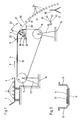
- solid mixture 1 containing non-magnetizable materials via a vibrating trough 2 at the end of the feed 3 on a conveyor belt 4 given up.
- the conveyor belt 4 rotating in the transport direction 5 wraps around a slideway 6 formed as an approximately quarter-hollow cylinder segment at the front end in the transport direction 5; in addition, the conveyor belt 4 is deflected by a rear deflection drum 7 arranged at the feed end 3 and a front, driven deflection drum 8 (drum motor).
- the speed of the conveyor belt 4, which is speed-controllable via the driven deflection drum 8, is greater than the conveying speed of the vibrating trough 2, so that when the belt 4 is transferred to the conveyor belt Pulling apart the solid mixture 1 already distributed in one layer on the vibrating trough 2 is achieved.
- the slideway 6 is connected upstream of the distance from the rear deflection drum 7 to the joint 9 of the rear end of the slideway 6 in the direction of transport 5, designed as a trough 11 with side walls 12 according to FIG. 3.
- the belt conveyor is anchored to the foundation 16 by means of supports 15.
- an electromagnet with its coil 19 is stationary in a closed housing 17 as a magnetic field generator 18, but is mounted in a rocker 21, about the pivot point 22 of which it can be pivoted in the direction of the double arrow 23.
- the position of the magnetic field generator 18 below the slide valve 6 in the housing 17 and thus the effective range of the magnetic field generator 18 schematically represented by the indicated field lines 24 in the vertical 25 and horizontal 26 approximately limited drop sector 27 can be adjusted.
- the magnetic field generator 18 is set so that its effective range indicated by the field lines 24 on the discharge line 28 (see FIG.
- the separation is supported by means of a separating saddle 35 which can be adjusted with its apex in a substantially horizontal direction.
- the non-magnetizable components 34 essentially fall down according to the throwing parabola 32 and, viewed in the transport direction 5, reach an area in front of the separating saddle 35.
Landscapes
- Structure Of Belt Conveyors (AREA)
- Sorting Of Articles (AREA)
Applications Claiming Priority (2)
| Application Number | Priority Date | Filing Date | Title |
|---|---|---|---|
| DE4014969 | 1990-05-10 | ||
| DE19904014969 DE4014969A1 (de) | 1990-05-10 | 1990-05-10 | Verfahren und vorrichtung zum abtrennen insbesondere schwachmagnetisierbarer materialien aus einem feststoffgemisch |
Publications (1)
| Publication Number | Publication Date |
|---|---|
| EP0455948A1 true EP0455948A1 (fr) | 1991-11-13 |
Family
ID=6406093
Family Applications (1)
| Application Number | Title | Priority Date | Filing Date |
|---|---|---|---|
| EP91103362A Withdrawn EP0455948A1 (fr) | 1990-05-10 | 1991-03-06 | Procédé et appareil de séparation de matériaux, en particulier faiblement magnétisables, à partir d'un mélange de solides |
Country Status (2)
| Country | Link |
|---|---|
| EP (1) | EP0455948A1 (fr) |
| DE (1) | DE4014969A1 (fr) |
Cited By (6)
| Publication number | Priority date | Publication date | Assignee | Title |
|---|---|---|---|---|
| EP1878505A1 (fr) | 2006-07-13 | 2008-01-16 | Technische Universiteit Delft | Procédé et dispositif de séparation de particules de métaux ferrugineux libérées dans de particules de métaux non-ferrugineux libérées au moyen d'un aimant statique |
| DE102006046356A1 (de) * | 2006-09-28 | 2008-04-03 | RWTH- Rheinisch-Westfälische Technische Hochschule Aachen | Verfahren und Vorrichtung zur Abtrennung von magnetisierbaren Stoffen aus einem Feststoffgemisch |
| EP1990599A1 (fr) * | 2007-05-07 | 2008-11-12 | Schweiz. Eidgenossenschaft vertr. durch das Eidg. Dep. VBS handelnd durch Logistikbasis der Armee | Collecteur de balles, ainsi que procédé et système destinés à leur récupération |
| NL2002730C2 (en) * | 2009-04-08 | 2010-10-11 | Univ Delft Tech | Method and apparatus for separating a non-ferous metal-comprising fraction from ferrous scrap. |
| NL2002736C2 (en) * | 2009-04-09 | 2010-10-12 | Univ Delft Tech | Method for separating magnetic pieces of material. |
| US11465158B2 (en) * | 2020-04-30 | 2022-10-11 | Mss, Inc. | Separation of ferrous materials |
Families Citing this family (6)
| Publication number | Priority date | Publication date | Assignee | Title |
|---|---|---|---|---|
| DE4317640A1 (de) * | 1993-05-27 | 1994-12-08 | Nsm Magnettechnik Gmbh | Einrichtung zur Lagebeeinflussung von Teilen aus elektrisch leitenden, nicht-ferromagnetischen Materialien, insbesondere zum Transportieren und/oder Sortieren von solchen Teilen |
| DE19722745A1 (de) * | 1997-05-30 | 1998-12-03 | Cafer Borucu | Trennung von Metallen aus einem Gemsich mit Nicht-Metallen |
| DE10003562A1 (de) * | 2000-01-27 | 2001-08-16 | Commodas Gmbh | Vorrichtung und Verfahren zum Aussortieren von metallischen Fraktionen aus einem Schüttgutstrom |
| DE102005002224A1 (de) * | 2005-01-18 | 2006-07-27 | Industriemaschinen-Bergbau-Service Gmbh | Verteilvorrichtung |
| NL2001322C2 (nl) | 2008-02-27 | 2009-08-31 | Univ Delft Tech | Werkwijze en inrichting voor het scheiden van vaste deeltjes met een onderling dichtheidsverschil. |
| DE102016122119A1 (de) | 2016-11-17 | 2018-05-17 | Hydro Aluminium Rolled Products Gmbh | Sortieranlage und Sortierverfahren |
Citations (3)
| Publication number | Priority date | Publication date | Assignee | Title |
|---|---|---|---|---|
| FR716806A (fr) * | 1931-05-08 | 1931-12-28 | Procédé et appareil de séparation magnétique de produits différents mélangés | |
| GB730405A (en) * | 1951-10-19 | 1955-05-25 | Veitscher Magnesitwerke Ag | Method and apparatus for the magnetic separation of loose material containing magnetisable parts |
| WO1988005696A1 (fr) * | 1987-01-30 | 1988-08-11 | Usx Engineers And Consultants, Inc. | Procede de separation avec un separateur magnetique de type a courroie |
-
1990
- 1990-05-10 DE DE19904014969 patent/DE4014969A1/de not_active Withdrawn
-
1991
- 1991-03-06 EP EP91103362A patent/EP0455948A1/fr not_active Withdrawn
Patent Citations (3)
| Publication number | Priority date | Publication date | Assignee | Title |
|---|---|---|---|---|
| FR716806A (fr) * | 1931-05-08 | 1931-12-28 | Procédé et appareil de séparation magnétique de produits différents mélangés | |
| GB730405A (en) * | 1951-10-19 | 1955-05-25 | Veitscher Magnesitwerke Ag | Method and apparatus for the magnetic separation of loose material containing magnetisable parts |
| WO1988005696A1 (fr) * | 1987-01-30 | 1988-08-11 | Usx Engineers And Consultants, Inc. | Procede de separation avec un separateur magnetique de type a courroie |
Cited By (9)
| Publication number | Priority date | Publication date | Assignee | Title |
|---|---|---|---|---|
| EP1878505A1 (fr) | 2006-07-13 | 2008-01-16 | Technische Universiteit Delft | Procédé et dispositif de séparation de particules de métaux ferrugineux libérées dans de particules de métaux non-ferrugineux libérées au moyen d'un aimant statique |
| EP2206558A1 (fr) | 2006-07-13 | 2010-07-14 | Technische Universiteit Delft | Procédé et dispositif pour la séparation de fragments de ferraille libérée à partir de fragments de ferraille non libérés au moyen d'un aimant statique |
| DE102006046356A1 (de) * | 2006-09-28 | 2008-04-03 | RWTH- Rheinisch-Westfälische Technische Hochschule Aachen | Verfahren und Vorrichtung zur Abtrennung von magnetisierbaren Stoffen aus einem Feststoffgemisch |
| EP1990599A1 (fr) * | 2007-05-07 | 2008-11-12 | Schweiz. Eidgenossenschaft vertr. durch das Eidg. Dep. VBS handelnd durch Logistikbasis der Armee | Collecteur de balles, ainsi que procédé et système destinés à leur récupération |
| NL2002730C2 (en) * | 2009-04-08 | 2010-10-11 | Univ Delft Tech | Method and apparatus for separating a non-ferous metal-comprising fraction from ferrous scrap. |
| WO2010117273A1 (fr) * | 2009-04-08 | 2010-10-14 | Technische Universiteit Delft | Procédé et appareil permettant la séparation d'une fraction de métal non ferreux a partir de ferraille |
| NL2002736C2 (en) * | 2009-04-09 | 2010-10-12 | Univ Delft Tech | Method for separating magnetic pieces of material. |
| WO2010117271A1 (fr) * | 2009-04-09 | 2010-10-14 | Technische Universiteit Delft | Utilisation d'un appareil pour séparer des morceaux magnétiques de matériaux |
| US11465158B2 (en) * | 2020-04-30 | 2022-10-11 | Mss, Inc. | Separation of ferrous materials |
Also Published As
| Publication number | Publication date |
|---|---|
| DE4014969A1 (de) | 1991-11-14 |
Similar Documents
| Publication | Publication Date | Title |
|---|---|---|
| EP0388626B1 (fr) | Appareil pour séparer des métaux non magnétisables d'un mélange de solides | |
| DE3872986T3 (de) | Verfahren und Apparat zur Ausscheidung von Nichteisenmetall-Stücken. | |
| DE69123596T2 (de) | Magnettrennungsystem für materialtrennungsanordnungen | |
| EP0455948A1 (fr) | Procédé et appareil de séparation de matériaux, en particulier faiblement magnétisables, à partir d'un mélange de solides | |
| EP0342330A2 (fr) | Appareil de séparation de métaux non magnétiques d'un mélange de solides | |
| DE19521415A1 (de) | Anordnung zum Abtrennen von nichtmagnetisierbaren Metallen aus einer Feststoffmischung | |
| DE69622336T2 (de) | Transportvorrichtung | |
| AT401020B (de) | Verfahren zur trennung eines heterogenen materialstromes in zwei ströme mit unterschiedlichen physikalischen eigenschaften und vorrichtung zur durchführung desselben | |
| DE19838170C2 (de) | Verfahren und Vorrichtung zur Wirbelstromscheidung von Materialgemischen in Teilchenform | |
| DE624224C (de) | Magnetscheider | |
| DE1627143A1 (de) | Verfahren und Vorrichtung zum Abtrennen eines Probestueckes von einem laufenden Band,insbesondere Metallband | |
| DE4223812C1 (fr) | ||
| EP0389767B1 (fr) | Appareil pour séparer des métaux non magnétisables d'un mélange de solides | |
| EP0912248B1 (fr) | Procede et dispositif pour separer des melanges de matieres finement divisees au moyen d'un champ magnetique | |
| DE2851319C2 (de) | Trommel-Magnetschneider | |
| DE102022104606B3 (de) | Pulverscheideanlage und verfahren zur abscheidung der ferromagnetischen fraktion eines pulvers von dessen nicht-ferromagnetischer fraktion | |
| EP3921084A1 (fr) | Procédé et dispositif pour séparer une charge | |
| CH614656A5 (en) | Device for conveying workpieces through an abrasive-blasting machine | |
| EP3488932A1 (fr) | Séparation des composants d'un mélange des métaux | |
| DE3423866C2 (de) | Vorrichtung zum Abtrennen nicht magnetisierbarer elektrisch leitfähiger Metallteile aus einem Feststoffgemisch | |
| DE2632210A1 (de) | Verfahren und vorrichtung zum trennen von magnetisierbarem und nichtmagnetisierbarem material, insbesondere bei der abfallaufbereitung | |
| DE4214428A1 (de) | Verfahren und vorrichtung zum trennen und sortieren magnetisierbarer und unmagnetisierbarer bestandteile eines gemisches voneinander und aufgabe-geraet hierfuer | |
| DE937495C (de) | Agglomeriervorrichtung | |
| DE102006054127A1 (de) | Vorrichtung zum Trennen von Nichteisenmetallen enthaltendem Trenngut | |
| DE2200694A1 (de) | Vorrichtung zur vereinzelung und weiterbefoerderung von insbesondere knueppelabschnitten |
Legal Events
| Date | Code | Title | Description |
|---|---|---|---|
| PUAI | Public reference made under article 153(3) epc to a published international application that has entered the european phase |
Free format text: ORIGINAL CODE: 0009012 |
|
| AK | Designated contracting states |
Kind code of ref document: A1 Designated state(s): AT BE CH DE ES FR GB IT LI NL SE |
|
| STAA | Information on the status of an ep patent application or granted ep patent |
Free format text: STATUS: THE APPLICATION HAS BEEN WITHDRAWN |
|
| 18W | Application withdrawn |
Withdrawal date: 19920321 |