EP0455951A2 - Dispositif d'alimentation pivotant pour dispositif de coupe d'une bande renforcée - Google Patents
Dispositif d'alimentation pivotant pour dispositif de coupe d'une bande renforcée Download PDFInfo
- Publication number
- EP0455951A2 EP0455951A2 EP91103466A EP91103466A EP0455951A2 EP 0455951 A2 EP0455951 A2 EP 0455951A2 EP 91103466 A EP91103466 A EP 91103466A EP 91103466 A EP91103466 A EP 91103466A EP 0455951 A2 EP0455951 A2 EP 0455951A2
- Authority
- EP
- European Patent Office
- Prior art keywords
- swivel
- feed device
- cord
- cutting
- cutting table
- Prior art date
- Legal status (The legal status is an assumption and is not a legal conclusion. Google has not performed a legal analysis and makes no representation as to the accuracy of the status listed.)
- Withdrawn
Links
- 230000005291 magnetic effect Effects 0.000 claims description 6
- 230000005294 ferromagnetic effect Effects 0.000 claims description 3
- 230000001360 synchronised effect Effects 0.000 claims description 3
- 230000002452 interceptive effect Effects 0.000 claims 1
- 239000002184 metal Substances 0.000 description 3
- 238000004519 manufacturing process Methods 0.000 description 1
- 239000000463 material Substances 0.000 description 1
- 230000000452 restraining effect Effects 0.000 description 1
- 230000003068 static effect Effects 0.000 description 1
- 230000001960 triggered effect Effects 0.000 description 1
Images


Classifications
-
- B—PERFORMING OPERATIONS; TRANSPORTING
- B26—HAND CUTTING TOOLS; CUTTING; SEVERING
- B26D—CUTTING; DETAILS COMMON TO MACHINES FOR PERFORATING, PUNCHING, CUTTING-OUT, STAMPING-OUT OR SEVERING
- B26D3/00—Cutting work characterised by the nature of the cut made; Apparatus therefor
- B26D3/003—Cutting work characterised by the nature of the cut made; Apparatus therefor specially adapted for cutting rubber
-
- B—PERFORMING OPERATIONS; TRANSPORTING
- B26—HAND CUTTING TOOLS; CUTTING; SEVERING
- B26D—CUTTING; DETAILS COMMON TO MACHINES FOR PERFORATING, PUNCHING, CUTTING-OUT, STAMPING-OUT OR SEVERING
- B26D7/00—Details of apparatus for cutting, cutting-out, stamping-out, punching, perforating, or severing by means other than cutting
- B26D7/06—Arrangements for feeding or delivering work of other than sheet, web, or filamentary form
- B26D7/0625—Arrangements for feeding or delivering work of other than sheet, web, or filamentary form by endless conveyors, e.g. belts
-
- B—PERFORMING OPERATIONS; TRANSPORTING
- B29—WORKING OF PLASTICS; WORKING OF SUBSTANCES IN A PLASTIC STATE IN GENERAL
- B29D—PRODUCING PARTICULAR ARTICLES FROM PLASTICS OR FROM SUBSTANCES IN A PLASTIC STATE
- B29D30/00—Producing pneumatic or solid tyres or parts thereof
- B29D30/06—Pneumatic tyres or parts thereof (e.g. produced by casting, moulding, compression moulding, injection moulding, centrifugal casting)
- B29D30/38—Textile inserts, e.g. cord or canvas layers, for tyres; Treatment of inserts prior to building the tyre
- B29D30/46—Cutting textile inserts to required shape
Definitions
- the invention relates to a swivel feed device for the clock-controlled feeding of cord tape or the like. to a cutting device with a support surface for the cord band which connects the supply roller frame which is movable on a circular path to the cutting table and which can be pivoted about the free front end.
- the contact surface, on which the cord band is usually dragged into the cutting device with the aid of a magnetic strip transport device is a flat metal plate lying on the front of the cutting table, which, when pivoted, that is to say the change in the angle of inclination with which the cord band enters the Cutting device runs in, slides on the table.
- a number of problems arise - triggered primarily by the softness and deformability of the still unvulcanized cord tape and in particular its stickiness and strong adhesion to any surface.
- the cord band lies on the front end when the entry angle is changed, i.e.
- the invention is therefore based on the object of designing a swivel feed device of the type mentioned at the outset such that, in the case of fully automatic operation, less deformation of the cord band or the like. and thus greater accuracy of the sections to be separated is achieved.
- the invention provides that the support surface is formed by a plurality of parallel conveyor belts, each of which runs above and below support plates with front and rear deflecting rollers, these telescopic tubes being rigid at the rear end on the supply roller frame and at the front end in a groove of the cutting table are pivoted and a conveyor belt length compensation device and a belt tensioning device are assigned to each conveyor belt.
- the support plates consist of the cutting table rigidly connected to the cutting device and an adjoining outer support table which can be pivoted with the supply roller frame, the slides running in the groove of the cutting table with the front deflection rollers being independent of one another can be adjusted via program-controlled drive devices in accordance with the swivel adjustment of the supply roll frame. Because of the swivel adjustment, the distance between the front deflecting rollers clearly changes from one another, this adjustment not taking place, so that a separate program control the sled is required independently. In each case viewed from the central axis, only two carriages equally distant from each other can be coupled to one another, since they must be adjusted with respect to the central plane in the same way against or away from it.
- the support plates are formed by the upper sides of telescopic tubes assigned to each conveyor belt and carrying the front and rear deflection rollers.
- the separate, independently controllable drive devices for the front deflection rollers can be omitted.
- the front ends of the telescopic tubes are connected by arms running laterally next to the lower run of the conveyor belt, each with a pivot pin of a linear guide slide sliding in the groove of the cutting table.
- the pivotable articulation of the telescopic tubes carrying the conveyor belts at the front end can be designed in a particularly simple and effective manner in an embodiment of the invention in such a way that the front end of each telescopic tube by arms extending laterally next to the lower run of the conveyor belt with a pivot pin one in the groove of the Cutting table sliding linear guide carriage is connected.
- This configuration ensures that the conveyor belts remain exactly parallel to one another when the feed device is pivoted, the telescopic tube lying in the central axis not changing its length, while the telescopic tubes shorten on one side and lengthen on the other.
- the belt compensation device with appropriate deflection rollers and a belt tensioning device ensures that these changes in length are automatically compensated.
- the inner end of the telescopic inner tube can be supported by a guide roller in the outer telescopic tube.
- an additional feed device in the form of clock-controlled movable transport bars lifting the cord belt should also be provided for driven conveyor belts, the drive device of which is synchronized with the drive of the conveyor belts.
- the transport strips can include magnetic strips that extend across the cord band with extendable and retractable magnets and, alongside the cord band, are connected to ferromagnetic counter-strips that engage under the cord band.
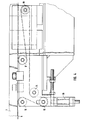
- a cutting device is indicated only schematically at 1, the knife plane and cutting plane of which is 2.
- the swivel feed device 3 for a cord band to be cut into sections for the production of car tires in the cutting device can be pivoted on a roadway, not shown in detail, between an angular position of approximately 15 ° inclination to the cutting edge 2 and 90 ° (shown in broken lines in FIG. 1).
- the swivel feed device comprises a supply roll frame 4, a transport section 5 with drive devices for pulling the cord band forward and of course also a drive device for the exact approach to any desired angle inclination to the cutting plane 2. For transporting the cord band omitted in FIG.
- a plurality - in practice much more than shown in the drawing - parallel conveyor belts 6 are provided, each of which runs above and below telescopic tubes 7, which consist of an outer tube 8 and an inner tube 10 sliding therein via a guide roller 9.
- telescopic tubes 7 which consist of an outer tube 8 and an inner tube 10 sliding therein via a guide roller 9.
- Deflection rollers 11 and 12 are arranged at the front and rear ends of such a telescopic tube, these deflection rollers sitting on a common axis and being able to be driven by a drive device 13.
- each telescopic tube is through a connecting plate 22, which is attached laterally next to the returning run 6b of the conveyor belt on the telescopic tube, connected to the pivot pin 23 of a parallel guide carriage 24, which runs on a rail 25 in a groove 26 of the cutting table and ensures the parallelism of the conveyor belts 6 even when the feed device is pivoted.
- FIG. 1 and 7 schematically indicate two magnetic transport strips 27 and 28, the drive and guidance of which are not shown in detail on guide rods supported on the cutting device and the supply roll frame, since such devices are well known.
- a transport bar comprises a magnetic bar 30 which can be transported and cut across and has a retractable magnet 31 as well as a ferromagnetic counter bar 32 which engages under the cord belt 29 including the supporting leading run 6a of the conveyor belts and which is attracted when the magnets 31 are extended.
- the feed device for the transport strips 27, 28 is synchronized with the belt drive.
- FIGS. 8 and 9 show a modified embodiment of the invention, in which the supports for the conveyor belts 6 are not designed as telescopic tubes, which are connected at the front end with linear guide carriages in the groove 26, but in which two rigid plate sections which can be pivoted about one another are provided are.
- the cutting table 33 with an arcuate outer edge 34 and an outer support table 35 rigidly connected to the supply roller frame and pivotable with it around the cutting table, with a corresponding arcuate inner edge 36 with which it is separated only by a very small gap 37 connects to the cutting table 33.
- 8 also shows how the respective lower run 6b of the conveyor belt 6 runs on the one hand under the cutting table 33 and on the other hand also under the support table 35, with the belt length compensation device and the belt tensioning device also being shown schematically under the latter.
Landscapes
- Engineering & Computer Science (AREA)
- Mechanical Engineering (AREA)
- Life Sciences & Earth Sciences (AREA)
- Forests & Forestry (AREA)
- Textile Engineering (AREA)
- Tyre Moulding (AREA)
Applications Claiming Priority (2)
| Application Number | Priority Date | Filing Date | Title |
|---|---|---|---|
| DE4014890 | 1990-05-09 | ||
| DE19904014890 DE4014890A1 (de) | 1990-05-09 | 1990-05-09 | Schwenkzufuehreinrichtung fuer cordband-schneidvorrichtungen |
Publications (2)
| Publication Number | Publication Date |
|---|---|
| EP0455951A2 true EP0455951A2 (fr) | 1991-11-13 |
| EP0455951A3 EP0455951A3 (en) | 1993-01-13 |
Family
ID=6406039
Family Applications (1)
| Application Number | Title | Priority Date | Filing Date |
|---|---|---|---|
| EP19910103466 Withdrawn EP0455951A3 (en) | 1990-05-09 | 1991-03-07 | Pivoting delivery device for reinforced belt cutter |
Country Status (2)
| Country | Link |
|---|---|
| EP (1) | EP0455951A3 (fr) |
| DE (1) | DE4014890A1 (fr) |
Cited By (2)
| Publication number | Priority date | Publication date | Assignee | Title |
|---|---|---|---|---|
| CN100482377C (zh) * | 2004-08-06 | 2009-04-29 | 张建浩 | 一种15°~70°钢丝帘布裁断机 |
| CN111945411A (zh) * | 2020-08-25 | 2020-11-17 | 北京阿尔法针织有限公司 | 一种新型断布机 |
Families Citing this family (3)
| Publication number | Priority date | Publication date | Assignee | Title |
|---|---|---|---|---|
| DE10201368C1 (de) * | 2002-01-16 | 2003-05-28 | Fischer Maschf Karl E | Schere zum Schneiden von Bandmaterial |
| DE10203447C1 (de) * | 2002-01-30 | 2003-06-26 | Fischer Maschf Karl E | Schere zum Abtrennen von Abschnitten von einem mittels einer Greifervorrichtung durchgezogenen Materialband, insbesondere einem Stahlcordband |
| CN103522340A (zh) * | 2013-07-30 | 2014-01-22 | 软控股份有限公司 | 裁断递料装置及其方法 |
Family Cites Families (7)
| Publication number | Priority date | Publication date | Assignee | Title |
|---|---|---|---|---|
| DE657314C (de) * | 1936-12-24 | 1938-03-02 | C G Haubold Akt Ges | Selbsteinstellende Foerderbandfuehrung an Quer- und Diagonalschneidern fuer Papierbahnen u. dgl. |
| DE684841C (de) * | 1938-11-26 | 1939-12-07 | Gerald Strecker Dipl Ing | Foerderbandeinrichtung an Quer- und Diagonalschneidern fuer Papierbahnen o. dgl. |
| US3130100A (en) * | 1956-07-17 | 1964-04-21 | Goodrich Co B F | Method and apparatus for butt splicing sheet material |
| DE1260131B (de) * | 1964-06-08 | 1968-02-01 | Continental Gummi Werke Ag | Einrichtung zum Zufuehren einer Bahn oder Platte aus Gummi zu einer Schneidmaschine |
| US3584528A (en) * | 1969-01-28 | 1971-06-15 | Uniroyal Englebert France | Bias cutter |
| US4010664A (en) * | 1976-03-19 | 1977-03-08 | The Goodyear Tire & Rubber Company | Bias ply cutter feed apparatus |
| DE2707917A1 (de) * | 1977-02-24 | 1978-08-31 | Fischer Maschf Karl E | Vorrichtung zum schneiden von beidseitig in gummi eingebetteten stahldrahtlitzen |
-
1990
- 1990-05-09 DE DE19904014890 patent/DE4014890A1/de active Granted
-
1991
- 1991-03-07 EP EP19910103466 patent/EP0455951A3/de not_active Withdrawn
Cited By (3)
| Publication number | Priority date | Publication date | Assignee | Title |
|---|---|---|---|---|
| CN100482377C (zh) * | 2004-08-06 | 2009-04-29 | 张建浩 | 一种15°~70°钢丝帘布裁断机 |
| CN111945411A (zh) * | 2020-08-25 | 2020-11-17 | 北京阿尔法针织有限公司 | 一种新型断布机 |
| CN111945411B (zh) * | 2020-08-25 | 2022-04-12 | 北京阿尔法针织有限公司 | 一种断布机 |
Also Published As
| Publication number | Publication date |
|---|---|
| EP0455951A3 (en) | 1993-01-13 |
| DE4014890A1 (de) | 1991-11-14 |
| DE4014890C2 (fr) | 1992-06-04 |
Similar Documents
| Publication | Publication Date | Title |
|---|---|---|
| EP0156127B1 (fr) | Dispositif pour palettisation | |
| DE3621357C1 (de) | Kappsaege zum Ablaengen von Brettern | |
| DE1679961B1 (de) | Vorrichtung zum Woelben einer sich in plastischen Zustand befindenden Platte mit einer Woelbeform | |
| DE4438207C2 (de) | Übergabevorrichtung für auf einem umlaufenden endlosen Zuführband in Querreihen ankommenden Gegenstände | |
| EP1667907B1 (fr) | Systeme pour charger des articles dans un compartiment de chargement, en particulier d'un avion, et pour les decharger | |
| DE2915180A1 (de) | Laengenveraenderlicher bandfoerderer | |
| AT506073A4 (de) | Anlage zur förderung von gütern | |
| EP0548661A1 (fr) | Dispositif de transport à bande | |
| EP0455951A2 (fr) | Dispositif d'alimentation pivotant pour dispositif de coupe d'une bande renforcée | |
| CH670809A5 (fr) | ||
| EP0694019A1 (fr) | Dispositif pour separer un produit d'une bande defilant en continu | |
| EP0087443B1 (fr) | Dispositif pour transporter des pieces a usiner allongees | |
| DE3703845A1 (de) | Vorrichtung zum vereinzeln gestapelter zuschnitte | |
| EP3722057A1 (fr) | Découpage de produits alimentaires | |
| EP0019036B1 (fr) | Dispositif pour empiler des produits de forme parallélépipédique, en particulier des imprimés, des journaux ou analogues de cette forme | |
| DE3733906A1 (de) | Umlenkvorrichtung fuer einen produktstrom, insbesondere von in schuppenform herangefuehrten papierprodukten | |
| DE4003024C2 (fr) | ||
| DE2618568A1 (de) | Zufuehr-vorrichtung fuer materialstaebe | |
| EP3369663B1 (fr) | Dispositif de bottelage pour pièces à usiner oblongues ainsi que procédé de bottelage de pièces à usiner oblongues | |
| DE1452017C3 (de) | Aufstell- und Verschiebevorrichtung für Walzstäbe, insbesondere für Profile | |
| AT404439B (de) | Vorrichtung zum verteilen von stabförmigen elementen | |
| EP0522237B1 (fr) | Appareil de pivotement pour alimentation d'un ruban de corde pour une trancheuse | |
| DE1652760C3 (de) | Für eine Tafelschere für Tafeln aus Blech, Kunststoff o.dgl. bestimmte Vorrichtung zum Unterstützen und Abfuhren der geschnittenen Tafeln | |
| DE29802355U1 (de) | Vorrichtung zum Transport und zur Vorbereitung von hohlen Profilstäben aus Kunststoff für die Bildung von Fensterrahmen | |
| DE10037658C2 (de) | Vorrichtung zum Aussortieren von Brettern aus einem Bretterteppich |
Legal Events
| Date | Code | Title | Description |
|---|---|---|---|
| PUAI | Public reference made under article 153(3) epc to a published international application that has entered the european phase |
Free format text: ORIGINAL CODE: 0009012 |
|
| AK | Designated contracting states |
Kind code of ref document: A2 Designated state(s): BE DE ES FR GB IT NL SE |
|
| PUAL | Search report despatched |
Free format text: ORIGINAL CODE: 0009013 |
|
| AK | Designated contracting states |
Kind code of ref document: A3 Designated state(s): BE DE ES FR GB IT NL SE |
|
| 17P | Request for examination filed |
Effective date: 19930505 |
|
| 17Q | First examination report despatched |
Effective date: 19940901 |
|
| STAA | Information on the status of an ep patent application or granted ep patent |
Free format text: STATUS: THE APPLICATION HAS BEEN WITHDRAWN |
|
| 18W | Application withdrawn |
Withdrawal date: 19950405 |