EP0455960B1 - Convertisseur réversible et son application comme élément de régulation d'un accumulateur d'énergie - Google Patents
Convertisseur réversible et son application comme élément de régulation d'un accumulateur d'énergie Download PDFInfo
- Publication number
- EP0455960B1 EP0455960B1 EP19910104111 EP91104111A EP0455960B1 EP 0455960 B1 EP0455960 B1 EP 0455960B1 EP 19910104111 EP19910104111 EP 19910104111 EP 91104111 A EP91104111 A EP 91104111A EP 0455960 B1 EP0455960 B1 EP 0455960B1
- Authority
- EP
- European Patent Office
- Prior art keywords
- magnetic memory
- switching element
- converter
- controllable
- valves
- Prior art date
- Legal status (The legal status is an assumption and is not a legal conclusion. Google has not performed a legal analysis and makes no representation as to the accuracy of the status listed.)
- Expired - Lifetime
Links
- 238000004146 energy storage Methods 0.000 title description 3
- 230000002441 reversible effect Effects 0.000 title 1
- 239000004065 semiconductor Substances 0.000 claims description 29
- 230000005540 biological transmission Effects 0.000 claims description 3
- 230000000087 stabilizing effect Effects 0.000 claims 1
- 238000007599 discharging Methods 0.000 description 10
- 238000010586 diagram Methods 0.000 description 6
- 230000008878 coupling Effects 0.000 description 5
- 238000010168 coupling process Methods 0.000 description 5
- 238000005859 coupling reaction Methods 0.000 description 5
- 239000003990 capacitor Substances 0.000 description 4
- 238000000034 method Methods 0.000 description 4
- 230000008901 benefit Effects 0.000 description 3
- 230000008569 process Effects 0.000 description 3
- 230000000903 blocking effect Effects 0.000 description 2
- 238000005457 optimization Methods 0.000 description 2
- 230000006641 stabilisation Effects 0.000 description 2
- 238000011105 stabilization Methods 0.000 description 2
- 230000003068 static effect Effects 0.000 description 2
- 230000007704 transition Effects 0.000 description 2
- 238000002474 experimental method Methods 0.000 description 1
- 238000010304 firing Methods 0.000 description 1
- 230000006870 function Effects 0.000 description 1
- 239000002887 superconductor Substances 0.000 description 1
- 239000000725 suspension Substances 0.000 description 1
Images

Classifications
-
- H—ELECTRICITY
- H01—ELECTRIC ELEMENTS
- H01F—MAGNETS; INDUCTANCES; TRANSFORMERS; SELECTION OF MATERIALS FOR THEIR MAGNETIC PROPERTIES
- H01F6/00—Superconducting magnets; Superconducting coils
- H01F6/006—Supplying energising or de-energising current; Flux pumps
- H01F6/008—Electric circuit arrangements for energising superconductive electromagnets
-
- H—ELECTRICITY
- H02—GENERATION; CONVERSION OR DISTRIBUTION OF ELECTRIC POWER
- H02M—APPARATUS FOR CONVERSION BETWEEN AC AND AC, BETWEEN AC AND DC, OR BETWEEN DC AND DC, AND FOR USE WITH MAINS OR SIMILAR POWER SUPPLY SYSTEMS; CONVERSION OF DC OR AC INPUT POWER INTO SURGE OUTPUT POWER; CONTROL OR REGULATION THEREOF
- H02M3/00—Conversion of DC power input into DC power output
- H02M3/02—Conversion of DC power input into DC power output without intermediate conversion into AC
- H02M3/04—Conversion of DC power input into DC power output without intermediate conversion into AC by static converters
- H02M3/10—Conversion of DC power input into DC power output without intermediate conversion into AC by static converters using discharge tubes with control electrode or semiconductor devices with control electrode
- H02M3/125—Conversion of DC power input into DC power output without intermediate conversion into AC by static converters using discharge tubes with control electrode or semiconductor devices with control electrode using devices of a thyratron or thyristor type requiring extinguishing means
- H02M3/135—Conversion of DC power input into DC power output without intermediate conversion into AC by static converters using discharge tubes with control electrode or semiconductor devices with control electrode using devices of a thyratron or thyristor type requiring extinguishing means using semiconductor devices only
- H02M3/137—Conversion of DC power input into DC power output without intermediate conversion into AC by static converters using discharge tubes with control electrode or semiconductor devices with control electrode using devices of a thyratron or thyristor type requiring extinguishing means using semiconductor devices only with automatic control of output voltage or current, e.g. switching regulators
- H02M3/142—Conversion of DC power input into DC power output without intermediate conversion into AC by static converters using discharge tubes with control electrode or semiconductor devices with control electrode using devices of a thyratron or thyristor type requiring extinguishing means using semiconductor devices only with automatic control of output voltage or current, e.g. switching regulators including plural semiconductor devices as final control devices for a single load
Definitions
- the invention is based on a two-quadrant converter according to the preamble of claims 1 and 2.
- the invention relates to a prior art as is known from EP-A1-0 088 445.
- the freewheeling current through a choke can be controlled alternately by 2 different bridge branches, so that a reduced switching frequency of the semiconductor valves results.
- the invention solves the problem of circuits. Specify two-quadrant converters that enable a lower load on the semiconductor valves used.
- An advantage of the invention is that some of the semiconductor valves can be designed for a lower electrical output.
- the number of semiconductor valves of the two-quadrant converter can be reduced to 2.
- a controllable valve connected in parallel to the magnetic memory enables the semiconductor valves of the two-quadrant converter to be further relieved in operating states in which the magnetic memory does not have to be charged or discharged.
- Fig. 1 shows an example of a network coupling the connection of a 3-phase 50 Hz state network (1) with a single-phase 16 2/3 Hz rail network (7) as a fully static "short coupling".
- the two power networks (1) and (7) are a positively commutated converter via a state network transformer (2), a line commutated converter or I converter (3), a direct voltage intermediate circuit which has an intermediate circuit choke (4) and an intermediate circuit capacitor (C) or U-converter (5) and a railway network transformer (6) connected to each other.
- the line-commutated converter (3) is designed as a conventional, anti-parallel thyristor converter. Its manipulated variable, the firing angle ( ⁇ ), is used in normal operation to keep the intermediate circuit voltage (U d ) constant and thus indirectly to balance the active power balance in the intermediate circuit.
- the forced commutated converter (5) is designed with GTO thyristors. With the help of its 2 manipulated variables, a phase angle ( ⁇ ) and an amplitude manipulated variable (a), the active and reactive power requirements of the rail network (7) can be taken into account independently of each other.
- the coil (L) for energy storage of z. B. 1 MWh can have a height of 3 m as a solenoid with a diameter of about 8.9 m.
- (I8) denotes a charge or discharge current through the two-quadrant converter (8).
- a switching ratio (k) is fed to the two-quadrant converter (8) as an electronically generated, rapidly variable manipulated variable.
- the two-quadrant converter (8) can be regarded as a DC voltage transformer with an electronically adjustable transmission ratio (k).
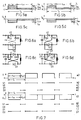
- FIG. 2 shows a two-quadrant converter (8) with a 1st controllable valve or thyristor (V1) in a 1st DC voltage line (9), the cathode of which via the magnetic memory (L) with the anode of a 2nd controllable valve or thyristor ( V2) is connected in a second DC voltage line (10).
- the intermediate circuit voltage (U d ) of the is on the DC voltage lines (9) and (10) DC link capacitor (C).
- the anode of the thyristor (V2) is connected to the anode of a diode (D1), the cathode of which is connected to the anode of the thyristor (V1).
- the cathode of the thyristor (V2) is connected to the anode of a diode (D2), the cathode of which is connected to the cathode of the thyristor (V1).
- Mechanical switches (S1) or (S2) or (S3) are provided in parallel branches to the diode (D1), the thyristor (V2) and the magnetic memory (L).
- V1, V2, D1, D2 The voltage design of the semiconductor valves (V1, V2, D1, D2) results from the intermediate circuit voltage (U d ), which results from the optimization of the converters (3, 5).
- the current design of the switchable valves (V1, V2) results from the maximum current (I Lmax ) of the superconducting magnet (L) and the maximum value of the switching ratio (k) when charging or its minimum value when discharging.
- the current design of the diodes (D1, D2) results from the maximum current (I Lmax ) of the superconducting magnet (L) and the minimum value of the switching ratio (k) when charging or from its maximum value when discharging.
- FIGS. 3a-3c which corresponds to that of FIG. 2, however the mechanical switches (S1 - S3) are missing.
- Force-commutated thyristors or switchable GTO thyristors (V1, V2) can be used as controllable valves, which have a blocking but no blocking capability.
- both thyristors (V1, V2) are conductive, cf. Fig. 3a.
- both thyristors (V1, V2) are blocked and the two diodes (D1, D2) are conductive, cf. Fig. 3c.
- a freewheel for the magnetic current (I L ) is alternately switched, see FIG. Fig. 3b. It is important that the freewheel is controlled alternately via D1 - V1 and via V2 - D2. The transition from loading to unloading and vice versa is possible at any time and without delay.
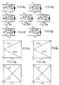
- the relative current load of the valves based on a continuous line, corresponding to the maximum current (I Lmax ), can be seen from FIGS. 4a) - 4i) and FIGS. 9a and 9b.
- the switching frequency of the valves and thus their switching losses are half as large as the clock frequency that is effective to the outside.
- FIGS. 4f) to 4i The on-time of the 4 valves (V1, V2, D1, D2) when the magnetic memory (L) is discharged is shown in FIGS. 4f) to 4i), the discharge taking place during the discharge times (t off ) according to FIG. 4a).
- the voltage (U L ) at the magnetic memory (L) is equal to 0 and during (t off ) is equal to -U L , cf. 7f).
- each valve is only switched from the non-conductive to the conductive state and vice versa every second switching cycle.
- FIG. 5b For the charging operation of the magnetic memory (L), the voltage drop across it (U L ) and the current (I8) through the two-quadrant converter (8) as a function of time (t) are plotted in FIG. 5b.
- the hatched areas indicate the same voltage or current mean values (U LM , I 8M ) during (t on ) or (t off ).
- Corresponding signal diagrams for the discharge operation of the magnetic memory (8) are shown in FIGS. 5c and 5d.
- a mechanical bypass switch (S3) can be provided for the magnetic memory (L).
- This bypass switch (S3) is particularly advantageous when the two-quadrant converter (8) is to remain in standby mode for longer periods (hours), the magnetic memory (L) being charged but not being charged or discharged.
- the bypass switch (S3) is closed, it must be ensured that not both controllable valves (V1, V2) are fired or conductive.
- Variant 1 is dynamically optimal because of the half switching frequency of the valves. 4 semiconductor valves are required, 2 of which are always in the current path.
- FIGS. 7a and 6b show the current flow when charging the magnetic memory (L), corresponding to the charging cycle shown in Fig. 7a). Only the mechanical switch (S2) parallel to the valve (V2) is required, which due to its smaller line resistance takes over the major part of the charging or freewheeling current and thus relieves the valve (V2).
- the relative current load of the 4 semiconductor valves (V1, V2, D1, D2) can be seen in FIGS. 7b) to 7e).
- the magnetic memory (L) could in principle be discharged according to variant 1.
- the mechanical switch (S1) provided in accordance with the circuits in FIGS. 6c and 6d parallel to the diode (D1) relieves the latter during the discharge process, the current flow of which can be seen in FIG. 6c.
- FIG. 6d shows the associated freewheeling current during (t on ), corresponding to the discharge cycle shown in FIG. 7f).
- the relative current load of the semiconductor valves (V1, V2, D1, D2) is shown in FIGS. 7g) to 7j). In principle, this discharge cycle could also be combined with the charge cycle of variant 1.
- Variant 2 has the advantage that practically only one semiconductor valve is energized in each case.
- Valves (V1) and (D2) are used one after the other for both loading and unloading.
- the switchable valve (V2) and the diode (D1) can be dimensioned much weaker in terms of current, since they only have to carry current in transition states, ie approx. 100 ms, depending on the quality of the mechanical switches.
- a mechanical bypass switch (S3) can be provided parallel to the magnetic memory (L), as in variant 1.
- FIGS. 8a to 8g The associated circuit, which is not part of the invention, can be seen in FIGS. 8a to 8g. Only a semiconductor valve (V1) and a diode (D2) that can be switched off are required. The losses in the two-quadrant converter (8) are minimal.
- FIGS. 8a and 8b The current flow when charging the magnetic memory (L) is shown in FIGS. 8a and 8b, that when discharging is shown in FIGS. 8f and 8g.
- Switching from charging mode to discharging mode takes place in succession in accordance with the switching states shown in FIGS. 8c to 8e.
- the changeover from unloading operation to loading operation takes place successively via the states according to FIGS. 8e, 8d and 8c.
- the relative current load of the semiconductor valves (V1, D2) when charging is shown in Fig. 10a and when discharging in Fig. 10b.
- the current load is plotted on the ordinate, the number 1 corresponding to a load of 100%.
- the switching ratio (k) is plotted on the abscissa. The same load ratios apply to variant 2.
- the converter (3) can have 2 antiparallel, 12-pulse thyristor converters in a circuit-free circuit. This is particularly advantageous if the intermediate circuit voltage (U d ) has to be kept constant and unipolar and a quick power reversal from the side of the rail network (7) is required.
- the two-quadrant converter (8) now makes it possible to achieve this power reversal on the converter (3) by reversing the intermediate circuit voltage (U d ) on its converter connections.
- This polarity reversal can take place in the currentless state of the converter (3) by means of conventional motorized isolators. With this measure, the component expenditure for the converter (3) can be halved.
- the power pause that occurs on the side of the state network (1) can be bridged by the two-quadrant converter (8), so that no disadvantageous power pause is noticeable for the rail network (7).
- Two-quadrant converters (8) with energy storage magnets (L) can also be used advantageously in so-called UPS systems for uninterruptible power supply.
- variant 2 The method with alternating freewheeling according to variant 1 can advantageously also be used in variant 2.
Landscapes
- Engineering & Computer Science (AREA)
- Power Engineering (AREA)
- Physics & Mathematics (AREA)
- Electromagnetism (AREA)
- Rectifiers (AREA)
- Dc-Dc Converters (AREA)
- Inverter Devices (AREA)
Claims (8)
- Convertisseur à deux quadrants (8), qui est activement connecté à au moins une mémoire magnétique (L),a) au moins un premier élément de commutation contrôlable (V1) dans une première ligne de courant continu (9) étant activement connecté par l'intermédiaire de l'au moins une mémoire magnétique (L) à au moins un deuxième élément de commutation contrôlable (V2, S2) dans une seconde ligne de courant continu (10),b) le côté, activement connecté à l'au moins une mémoire magnétique (L), de l'au moins un deuxième élément de commutation (V2, S2) étant connecté par l'intermédiaire d'un troisième tube électronique (D1) au côté du premier élément de commutation (V1) qui n'est pas activement connecté à l'au moins une mémoire magnétique (L),c) le côté, non activement connecté à l'au moins une mémoire magnétique (L), de l'au moins un deuxième élément de commutation (V2, S2) étant connecté par l'intermédiaire d'un quatrième tube électronique (D2) au côté du premier élément de commutation (V1) qui est activement connecté à l'au moins une mémoire magnétique (L), etd) les premier et deuxième éléments de commutation contrôlables étant des tubes électroniques à semiconducteurs (V1, V2),
caractérisé en ce quee) un élément de commutation mécanique contrôlable (S2) est connecté en parallèle à au moins un des tubes électroniques à semiconducteurs contrôlables (V1, V2). - Convertisseur à deux quadrants (8), qui est activement connecté à un moins une mémoire magnétique (L),a) au moins un premier élément de commutation contrôlable (V1) dans une première ligne de courant continu (9) étant activement connecté par l'intermédiaire de l'au moins une mémoire magnétique (L) à au moins un deuxième élément de commutation contrôlable (V2, S2) dans une seconde ligne de courant continu (10),b) le côté, activement connecté à l'au moins une mémoire magnétique (L), de l'au moins un deuxième élément de commutation (V2, S2) étant connecté par l'intermédiaire d'un troisième tube électronique (D1) au côté du premier élément de commutation (V1) qui n'est pas activement connecté à l'au moins une mémoire magnétique (L),c) le côté, non activement connecté à l'au moins une mémoire magnétique (L), de l'au moins un deuxième élément de commutation (V2, S2) étant connecté par l'intermédiaire d'un quatrième tube électronique (D2) au côté du premier élément de commutation (V1) qui est activement connecté à l'au moins une mémoire magnétique (L), etd) les troisième et quatrième tubes électroniques (D1, D2) étant des tubes électroniques à semiconducteurs,
caractérisé en ce quee) un élément de commutation mécanique contrôlable (S1) est connecté en parallèle à au moins un des deux troisième et quatrième tubes électroniques à semiconducteurs (D1, D2). - Convertisseur à deux quadrants (8) selon la revendication 2, caractérisé en ce que le premier ou deuxième élément de commutation contrôlable est un élément de commutation mécanique contrôlable (S2).
- Convertisseur à deux quadrants (8) selon la revendication 2,a) les premier et deuxième éléments de commutation contrôlables étant des tubes électroniques à semiconducteurs contrôlables (V1, V2),
caractérisé en ce queb) un élément de commutation mécanique contrôlable (S2) est connecté en parallèle à au moins un des tubes électroniques à semiconducteurs contrôlables. - Convertisseur à deux quadrants (8) selon la revendication 1,a) les troisième et quatrième tubes électroniques (D1, D2) étant des tubes électroniques à semiconducteurs,
caractérisé en ce queb) un élément de commutation mécanique contrôlable (S1) est connecté en parallèle à au moins un des deux troisième et quatrième tubes électroniques. - Convertisseur à deux quadrants (8) selon la revendication 1, caractérisé en ce que le troisième ou quatrième tube électronique est un élément de commutation mécanique contrôlable (S1).
- Convertisseur à deux quadrants (8) selon l'une des revendications 1 à 6, caractérisé en ce qu'un autre élément de commutation mécanique (S3) est connecté directement en parallèle à l'au moins une mémoire magnétique (L).
- Utilisation d'un convertisseur à deux quadrants (8) selon l'une des revendications 1 à 7 pour stabiliser la transmission de puissance dans une connexion de réseau, dans laquelle le convertisseur à deux quadrants (8) ayant une mémoire d'énergie (L) est connecté à un circuit courant continu intermédiare d'un convertisseur de la connexion de réseau ayant au moins un convertisseur commuté en ligne (3) et ayant au moins un convertisseur auto-commuté (5).
Applications Claiming Priority (2)
| Application Number | Priority Date | Filing Date | Title |
|---|---|---|---|
| CH179090 | 1990-05-08 | ||
| CH1790/90 | 1990-05-08 |
Publications (2)
| Publication Number | Publication Date |
|---|---|
| EP0455960A1 EP0455960A1 (fr) | 1991-11-13 |
| EP0455960B1 true EP0455960B1 (fr) | 1994-11-09 |
Family
ID=4218666
Family Applications (1)
| Application Number | Title | Priority Date | Filing Date |
|---|---|---|---|
| EP19910104111 Expired - Lifetime EP0455960B1 (fr) | 1990-05-08 | 1991-03-16 | Convertisseur réversible et son application comme élément de régulation d'un accumulateur d'énergie |
Country Status (7)
| Country | Link |
|---|---|
| US (1) | US5204548A (fr) |
| EP (1) | EP0455960B1 (fr) |
| JP (1) | JPH04281345A (fr) |
| BR (1) | BR9101845A (fr) |
| CA (1) | CA2039915A1 (fr) |
| DE (1) | DE59103465D1 (fr) |
| ES (1) | ES2066249T3 (fr) |
Families Citing this family (23)
| Publication number | Priority date | Publication date | Assignee | Title |
|---|---|---|---|---|
| DE19539573A1 (de) * | 1995-10-25 | 1997-04-30 | Asea Brown Boveri | Summenlöschkreis für einen Thyristor-Stromrichter |
| US5889659A (en) * | 1996-05-06 | 1999-03-30 | Superconductivity, Inc. | System for estimating a load to optimize a backup energy system response |
| US5661646A (en) * | 1996-09-25 | 1997-08-26 | The Babcock & Wilcox Company | Multi-phase DC-DC chopper with different number of phases |
| US6215202B1 (en) * | 1998-05-21 | 2001-04-10 | Bechtel Enterprises Inc. | Shunt connected superconducting energy management system having a single switchable connection to the grid |
| US6072304A (en) * | 1999-07-21 | 2000-06-06 | Regent Lighting Corporation | Circuit and method for triggering a thyristor |
| US6960203B2 (en) * | 2002-06-26 | 2005-11-01 | Ethicon, Inc. | Thermal ablation with deployable cage |
| CN101252290B (zh) * | 2008-03-31 | 2010-11-10 | 江苏双登集团有限公司 | 基于超级电容器的风电变桨ups系统 |
| WO2018231810A1 (fr) * | 2017-06-12 | 2018-12-20 | Tae Technologies, Inc. | Dispositifs de commande du courant par hystérésis à plusieurs niveaux et leurs procédés de commande |
| EA202090065A1 (ru) | 2017-06-16 | 2020-04-17 | Таэ Текнолоджиз, Инк. | Многоуровневые контроллеры напряжения гистерезиса для модуляторов напряжения и способы для их управления |
| CN107332222B (zh) * | 2017-07-28 | 2020-09-15 | 尹向阳 | 一种适用于大功率的直流开关灭弧装置 |
| MX2020009845A (es) | 2018-03-22 | 2020-10-15 | Tae Tech Inc | Sistemas y metodos para gestion y control de potencia. |
| CN108962534B (zh) * | 2018-08-24 | 2023-06-27 | 中国科学院合肥物质科学研究院 | 一种一体化组合参数可调式超大功率换流装置 |
| CN109888576A (zh) * | 2018-11-07 | 2019-06-14 | 广州金升阳科技有限公司 | 一种适用于直流电源的插座 |
| CA3134697A1 (fr) | 2019-03-29 | 2020-10-08 | Tae Technologies, Inc. | Systemes d'energie bases sur un module ayant des modules de source de convertisseur et procedes associes |
| US12556017B2 (en) | 2019-05-30 | 2026-02-17 | Tae Technologies, Inc. | Advanced battery charging on modular levels of energy storage systems |
| CA3191441A1 (fr) | 2020-04-14 | 2021-10-21 | Tae Technologies, Inc. | Systemes, dispositifs et procedes pour charger et decharger des systemes d'energie en cascade utilisant des modules |
| CA3178859A1 (fr) | 2020-04-14 | 2021-10-21 | Tae Technologies, Inc. | Systemes modulaires d'energie en cascade dotes d'un appareil de refroidissement et ayant une capacite de source d'energie remplacable |
| IL298081A (en) | 2020-05-14 | 2023-01-01 | Tae Tech Inc | Systems, devices and methods for rail-based electric vehicles and other electric vehicles with modular cascaded energy systems |
| US20240359595A1 (en) * | 2020-08-24 | 2024-10-31 | Tae Technologies, Inc. | Modular Cascaded Energy Systems with a Cooling Apparatus and with Replaceable Energy Source Capability |
| AU2021350186A1 (en) | 2020-09-28 | 2023-05-11 | Tae Technologies, Inc. | Multi-phase module-based energy system frameworks and methods related thereto |
| WO2022072330A1 (fr) | 2020-09-30 | 2022-04-07 | Tae Technologies, Inc. | Systèmes, dispositifs et procédés pour un équilibrage intraphase et interphase dans des systèmes d'énergie en cascade à base de modules |
| AU2022207104A1 (en) | 2021-01-13 | 2023-07-20 | Tae Technologies, Inc. | Systems, devices, and methods for module-based cascaded energy systems |
| EP4367770A4 (fr) | 2021-07-07 | 2025-06-18 | TAE Technologies, Inc. | Systèmes, dispositifs et procédés pour des systèmes d'énergie en cascade reposant sur des modules configurés pour servir d'interface avec des sources d'énergie renouvelable |
Family Cites Families (6)
| Publication number | Priority date | Publication date | Assignee | Title |
|---|---|---|---|---|
| BE743468A (fr) * | 1968-12-27 | 1970-05-28 | ||
| DE2242353B2 (de) * | 1972-08-29 | 1976-11-04 | Messerschmitt-Bölkow-Blohm GmbH, 8000 München | Einrichtung zur stromversorgung von trag- und fuehrungsmagneten eines magnetschwebefahrzeuges |
| US4079305A (en) * | 1975-10-17 | 1978-03-14 | Wisconsin Alumni Research Foundation | Power supply for high power loads |
| JPS58154345A (ja) * | 1982-03-09 | 1983-09-13 | 三菱電機株式会社 | コイル間エネルギ−転送回路 |
| US4599519A (en) * | 1984-05-16 | 1986-07-08 | The United States Of America As Represented By The United States Department Of Energy | Superconducting magnetic energy storage for asynchronous electrical systems |
| JP2543336B2 (ja) * | 1985-05-15 | 1996-10-16 | 三菱電機株式会社 | 超電導コイル・エネルギ−貯蔵回路 |
-
1991
- 1991-03-16 EP EP19910104111 patent/EP0455960B1/fr not_active Expired - Lifetime
- 1991-03-16 ES ES91104111T patent/ES2066249T3/es not_active Expired - Lifetime
- 1991-03-16 DE DE59103465T patent/DE59103465D1/de not_active Expired - Fee Related
- 1991-04-05 CA CA 2039915 patent/CA2039915A1/fr not_active Abandoned
- 1991-04-09 US US07/682,237 patent/US5204548A/en not_active Expired - Fee Related
- 1991-05-07 BR BR9101845A patent/BR9101845A/pt not_active Application Discontinuation
- 1991-05-08 JP JP3102562A patent/JPH04281345A/ja active Pending
Non-Patent Citations (1)
| Title |
|---|
| Murakami: "Application of Superconductive Magnet Energy Storage to improvePower System Dynamic Performance" * |
Also Published As
| Publication number | Publication date |
|---|---|
| BR9101845A (pt) | 1991-12-17 |
| EP0455960A1 (fr) | 1991-11-13 |
| CA2039915A1 (fr) | 1991-11-09 |
| ES2066249T3 (es) | 1995-03-01 |
| US5204548A (en) | 1993-04-20 |
| JPH04281345A (ja) | 1992-10-06 |
| DE59103465D1 (de) | 1994-12-15 |
Similar Documents
| Publication | Publication Date | Title |
|---|---|---|
| EP0455960B1 (fr) | Convertisseur réversible et son application comme élément de régulation d'un accumulateur d'énergie | |
| DE19607704B4 (de) | Vorrichtung zur magnetischen Anregung von neuro-muskularem Gewebe | |
| AT403865B (de) | Spannungsumsetzungsvorrichtung für einen gleichspannungsverbraucher | |
| DE4413163A1 (de) | Schaltungsanordnung mit einem Wechselrichter | |
| DE2652275A1 (de) | Einrichtung ohne prinzipbedingte verluste zur entnahme von praktisch rein sinusfoermigem, netzfrequentem strom aus wechsel- oder drehspannungsnetzen und zur ueberfuehrung der entnommenen elektrischen energie in galvanisch verbundene gleichspannungssysteme oder gleichspannungszwischensysteme | |
| DE69610000T2 (de) | Leistungswandler | |
| DE1806465A1 (de) | Wechselrichteranordnung | |
| DE3490150C2 (fr) | ||
| EP3332466A1 (fr) | Onduleur inverseur de polarité et avec capacité de puissance réactive ainsi que procédé d'inversion de polarité | |
| DE3523622C2 (fr) | ||
| DE1613979A1 (de) | Gleichspannungskonverter | |
| DE3714175C2 (fr) | ||
| EP0489947B1 (fr) | Circuit d'extinction | |
| EP0270920A2 (fr) | Procédé et dispositif de production de signaux de courant d'émission dans un réseau de distribution d'énergie à courant alternatif | |
| DE4447406C1 (de) | GTO-Stromrichter mit weicher Kommutierung | |
| DE2816361A1 (de) | Verfahren zum betrieb eines leistungskondensators zur blindstromkompensation | |
| DE4303147C1 (de) | GTO-Stromrichter mit quasi-resonantem Gleichspannungszwischenkreis | |
| DE1513725B2 (de) | Gleichspannungsregler | |
| DE2339034C2 (de) | Selbstgeführter Wechselrichter | |
| DE4413382C2 (de) | Drehstrom-Gleichrichterschaltung | |
| DE4342414A1 (de) | Schaltungsanordnung zur Energieübertragung zwischen einem Gleichstrom- und einem Gleichspannungskreis und Verfahren zur Steuerung der Schaltung | |
| DE3635401C2 (fr) | ||
| DE2360426A1 (de) | Selbstgesteuerter wechselrichter mit steuerbaren hauptventilen in mittelpunktschaltung | |
| AT283509B (de) | Wechselrichter und Verwendung desselben als Frequenzwandler | |
| DE2159397B2 (de) | Speiseschaltung für einen von einer ein- oder mehrphasigen Wechselstromquelle gespeisten Gleichstromverbraucher |
Legal Events
| Date | Code | Title | Description |
|---|---|---|---|
| PUAI | Public reference made under article 153(3) epc to a published international application that has entered the european phase |
Free format text: ORIGINAL CODE: 0009012 |
|
| AK | Designated contracting states |
Kind code of ref document: A1 Designated state(s): CH DE ES FR GB IT LI |
|
| 17P | Request for examination filed |
Effective date: 19920307 |
|
| 17Q | First examination report despatched |
Effective date: 19931118 |
|
| GRAA | (expected) grant |
Free format text: ORIGINAL CODE: 0009210 |
|
| AK | Designated contracting states |
Kind code of ref document: B1 Designated state(s): CH DE ES FR GB IT LI |
|
| REF | Corresponds to: |
Ref document number: 59103465 Country of ref document: DE Date of ref document: 19941215 |
|
| ITF | It: translation for a ep patent filed | ||
| ET | Fr: translation filed | ||
| GBT | Gb: translation of ep patent filed (gb section 77(6)(a)/1977) |
Effective date: 19950116 |
|
| REG | Reference to a national code |
Ref country code: ES Ref legal event code: FG2A Ref document number: 2066249 Country of ref document: ES Kind code of ref document: T3 |
|
| PLBE | No opposition filed within time limit |
Free format text: ORIGINAL CODE: 0009261 |
|
| STAA | Information on the status of an ep patent application or granted ep patent |
Free format text: STATUS: NO OPPOSITION FILED WITHIN TIME LIMIT |
|
| 26N | No opposition filed | ||
| PGFP | Annual fee paid to national office [announced via postgrant information from national office to epo] |
Ref country code: GB Payment date: 20000211 Year of fee payment: 10 |
|
| PGFP | Annual fee paid to national office [announced via postgrant information from national office to epo] |
Ref country code: CH Payment date: 20000221 Year of fee payment: 10 |
|
| PGFP | Annual fee paid to national office [announced via postgrant information from national office to epo] |
Ref country code: FR Payment date: 20000224 Year of fee payment: 10 Ref country code: DE Payment date: 20000224 Year of fee payment: 10 |
|
| PGFP | Annual fee paid to national office [announced via postgrant information from national office to epo] |
Ref country code: ES Payment date: 20000321 Year of fee payment: 10 |
|
| PG25 | Lapsed in a contracting state [announced via postgrant information from national office to epo] |
Ref country code: GB Free format text: LAPSE BECAUSE OF NON-PAYMENT OF DUE FEES Effective date: 20010316 |
|
| PG25 | Lapsed in a contracting state [announced via postgrant information from national office to epo] |
Ref country code: ES Free format text: LAPSE BECAUSE OF NON-PAYMENT OF DUE FEES Effective date: 20010317 |
|
| PG25 | Lapsed in a contracting state [announced via postgrant information from national office to epo] |
Ref country code: LI Free format text: LAPSE BECAUSE OF NON-PAYMENT OF DUE FEES Effective date: 20010331 Ref country code: CH Free format text: LAPSE BECAUSE OF NON-PAYMENT OF DUE FEES Effective date: 20010331 |
|
| GBPC | Gb: european patent ceased through non-payment of renewal fee |
Effective date: 20010316 |
|
| REG | Reference to a national code |
Ref country code: CH Ref legal event code: PL |
|
| PG25 | Lapsed in a contracting state [announced via postgrant information from national office to epo] |
Ref country code: FR Free format text: LAPSE BECAUSE OF NON-PAYMENT OF DUE FEES Effective date: 20011130 |
|
| REG | Reference to a national code |
Ref country code: FR Ref legal event code: ST |
|
| PG25 | Lapsed in a contracting state [announced via postgrant information from national office to epo] |
Ref country code: DE Free format text: LAPSE BECAUSE OF NON-PAYMENT OF DUE FEES Effective date: 20020101 |
|
| REG | Reference to a national code |
Ref country code: ES Ref legal event code: FD2A Effective date: 20030203 |
|
| PG25 | Lapsed in a contracting state [announced via postgrant information from national office to epo] |
Ref country code: IT Free format text: LAPSE BECAUSE OF NON-PAYMENT OF DUE FEES;WARNING: LAPSES OF ITALIAN PATENTS WITH EFFECTIVE DATE BEFORE 2007 MAY HAVE OCCURRED AT ANY TIME BEFORE 2007. THE CORRECT EFFECTIVE DATE MAY BE DIFFERENT FROM THE ONE RECORDED. Effective date: 20050316 |