EP0455989B1 - Système de transport entre différents niveaux de hauteur pour des bobines ou des tubes de bobines posées verticalement sur des supports indépendants - Google Patents
Système de transport entre différents niveaux de hauteur pour des bobines ou des tubes de bobines posées verticalement sur des supports indépendants Download PDFInfo
- Publication number
- EP0455989B1 EP0455989B1 EP91105386A EP91105386A EP0455989B1 EP 0455989 B1 EP0455989 B1 EP 0455989B1 EP 91105386 A EP91105386 A EP 91105386A EP 91105386 A EP91105386 A EP 91105386A EP 0455989 B1 EP0455989 B1 EP 0455989B1
- Authority
- EP
- European Patent Office
- Prior art keywords
- transport
- individual supports
- individual
- transport system
- entrainment members
- Prior art date
- Legal status (The legal status is an assumption and is not a legal conclusion. Google has not performed a legal analysis and makes no representation as to the accuracy of the status listed.)
- Expired - Lifetime
Links
- 238000012546 transfer Methods 0.000 claims description 28
- 230000008859 change Effects 0.000 claims description 5
- 239000003302 ferromagnetic material Substances 0.000 claims description 2
- 230000032258 transport Effects 0.000 description 84
- 239000000969 carrier Substances 0.000 description 77
- 238000004804 winding Methods 0.000 description 5
- 238000009987 spinning Methods 0.000 description 4
- 230000015572 biosynthetic process Effects 0.000 description 3
- 238000013461 design Methods 0.000 description 2
- 238000003825 pressing Methods 0.000 description 2
- 230000008719 thickening Effects 0.000 description 2
- 238000010276 construction Methods 0.000 description 1
- 230000005484 gravity Effects 0.000 description 1
- 238000004519 manufacturing process Methods 0.000 description 1
- 230000001404 mediated effect Effects 0.000 description 1
- 238000000034 method Methods 0.000 description 1
- 230000008569 process Effects 0.000 description 1
- 238000012545 processing Methods 0.000 description 1
- 238000000926 separation method Methods 0.000 description 1
- 238000012549 training Methods 0.000 description 1
- 230000007704 transition Effects 0.000 description 1
Images


Classifications
-
- B—PERFORMING OPERATIONS; TRANSPORTING
- B65—CONVEYING; PACKING; STORING; HANDLING THIN OR FILAMENTARY MATERIAL
- B65H—HANDLING THIN OR FILAMENTARY MATERIAL, e.g. SHEETS, WEBS, CABLES
- B65H67/00—Replacing or removing cores, receptacles, or completed packages at paying-out, winding, or depositing stations
- B65H67/06—Supplying cores, receptacles, or packages to, or transporting from, winding or depositing stations
-
- B—PERFORMING OPERATIONS; TRANSPORTING
- B65—CONVEYING; PACKING; STORING; HANDLING THIN OR FILAMENTARY MATERIAL
- B65H—HANDLING THIN OR FILAMENTARY MATERIAL, e.g. SHEETS, WEBS, CABLES
- B65H2701/00—Handled material; Storage means
- B65H2701/30—Handled filamentary material
- B65H2701/31—Textiles threads or artificial strands of filaments
Definitions
- the invention relates to a transport system according to the preamble of the first claim.
- JP-A-52-25 139 describes a transport system in which cops and sleeves are transported with their individual carriers in different transport planes. The respective horizontal transport takes place by means of frictional engagement through conveyor belts, the individual carriers being guided through guide slots along these transport routes.
- the transport levels are changed using elevators, which are formed by lifting and lowering transport track sections. Several individual carriers are combined in groups on these transport sections. These elevators work discontinuously and are not suitable for a high throughput of single girders.
- the generic DE-OS 36 30 670 also describes a transport system for coils and coil sleeves placed on independent individual carriers, in which parts of the transport path leading obliquely upwards are provided to bridge the height differences.
- This transport system can be used advantageously for the formation of an operating aisle between connected machines.
- the individual carriers In order to ensure that the individual carriers are also carried along by the conveyor belt in the transport sections which run obliquely upwards or downwards, they must at the same time rest against the plates forming the guide slot on the top of their base plate. It must be ensured that the frictional force between the conveyor belt and the individual carrier is significantly greater than the frictional force between the individual carrier and the guide plates. For this purpose, the conveyor belt must be pressed resiliently against the individual carrier so that it is also taken along.
- DE-OS 37 43 882 describes a similar system, but with the guide plates being replaced by flexible, round guides, which also have this guide slot for the base of the Form single carrier.
- the solution described in this publication allows the individual carriers to tilt during their transport.
- the transport belts, which also transport the individual carriers by friction, must be very narrow, since they are folded by 90 degrees at deflection points.
- such a pressing force of the transport belt against the individual carrier must be secured over the entire course of the route, with which friction can be achieved which clearly exceeds the sliding friction between the top of the individual carrier base and the guides forming the guide slot.
- the system is therefore also subject to relatively high wear.
- the object of the invention is to propose a simply constructed transport system which ensures high transport capacity, a small space requirement and constant functional reliability for single carriers with attached coils or bobbin sleeves between transport levels of different heights.
- the carriers attached to the rotating means of transport ensure that the individual carriers are securely grasped at the transfer point and are transported without any frictional forces. This minimizes wear on the individual carriers as well as the entire transport system. In this way, the functionality of the entire system is significantly extended.
- the avoidance of the frictional forces also prevents the different wear of the individual carriers and the transport route sections. As a result, a problem of known systems does not arise, which is that the different wear results in different frictional forces and thus leading to different entrainment of the individual carriers along the transport route. In known devices, this problem quickly increases to such an extent that it no longer functions.
- the drivers ensure that the individual carriers can be tilted into the new transport position without any significant space requirements. Due to the continuous operation of the system, a very high transport capacity is achieved. The simple structure ensures high functional reliability.
- a separation device of the pallets can be dispensed with at the delivery point of the individual carriers.
- this also increases the possible transport capacity.
- the invention also makes it possible to tilt horizontally delivered individual carriers at the delivery point by 90 degrees without the need for a bulky transport path curvature, as is known from the prior art.
- the individual carriers can be transferred from the carriers to another conveyor belt just as easily and continuously.
- Different variants for fixing the position of the individual carriers on the carriers do not cause any significant additional friction.
- Their structure is very simple.
- the transport system according to the invention also provides as a variant that the individual carriers remain on the carriers all the way through a cop bridge. It is also possible to do both To use trumes of the circulating means of transport for the transport of individual carriers, which means that capacity is doubled without taking up additional space.
- Transport routes are designed like a bridge, with an upper horizontal part being arranged at least at a height that allows free passage for people.
- a bridge of this type it is particularly problematic to lift the individual carriers with attached cops or sleeves from the level of the transport routes provided in the vicinity of the ground in the respective machine area to the level of the upper horizontal bridge part or to lower them again.
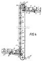
- cops 2 placed on individual carriers 1 are fed along a transport path 3 to a vertical transport path.
- the single carrier 1 have spokes 1 ', which connect a socket 1 ⁇ provided with the plug-in mandrel for the cop 2 with a casing ring 1 ′′′.
- the conveyor track 3 has a conveyor belt 4, which feeds the individual carriers 1 with cops 2 of the transfer point to the vertical transport route.
- the conveyor belt 4 is deflected by a pulley 4 '.
- the drive of this conveyor belt 4 is not shown here.
- the individual carriers are guided on their casing rings 1 ′′′ by guide rails 5 which have an angled part 5 'at the transfer point of the individual carriers. As a result, the individual carriers 1 are displaced transversely to the transport direction of the conveyor belt 4.
- the foremost individual carrier 1 abuts against a guide plate 10 or a stopper acting projection 10 'of this guide plate 10. In this position, it is gripped by a driving pin 13 fastened to a chain 12, which first lifts the front part of the single carrier and then into a of the openings between the spokes 1 'penetrates with further tilting of the single carrier.
- the single carrier tilts into a vertical position. In this vertical position, the individual carrier is then exclusively carried by the driver 13 held on which the jacket ring 1 ′′′ of the single carrier rests with its inside.
- an upper guide plate 6 is arranged such that it completely pushes the individual carrier 1 onto the driving pin 13 after it has tilted.
- the guide plate 6 then merges into a guide plate 11, by means of which the individual carriers are prevented from tipping during transport from the vertical position together with an opposite guide plate which is also provided with the reference number 11.
- the guide plates 11 cooperate with guide plates 10 on which the individual carriers slide with their underside and between which the driver pins 13 pass.
- the driver pins 13 contain notches 13 ', which are arranged so that they are in the transport direction of the driver 13 at the front.
- the notches 13 ' are attached at such a distance from the chain 12 that they capture the single carrier 1 ready for transfer on the inside of its casing ring 1 ′′′ and form a fulcrum during the tilting movement of the single carrier.
- the individual carrier 1 is then pushed further onto the driving pin 13. Through this notch 13 'it is ensured that the individual carrier can not slide down again when it is received by the driving pin 13.
- a guide plate 7 On the side opposite the guide plate 6, a guide plate 7 is attached, which has hinges 8, about which it can be pivoted. This guide plate 7 is pulled by a tension spring 9 against one of the guide plates 11. This resilient attachment of the guide plate 7 prevents individual carriers from jamming during the takeover.
- the circumferential chain which carries the driving pins 13 has a transport direction which laterally leads obliquely upwards from the stop position of the foremost single carrier to be taken over and then transitions into a vertical distance in order to achieve a transport direction component transverse to the tilting plane of the cop 2 on.
- the chain 12 has, in addition to sprockets 14 to 17, a sprocket 18 which conveys to the chain 12 the change in transport direction provided in this area. Due to this special design of the single carrier take-over, the tilting or tilted cop 2 is guided laterally away from the feed direction of the subsequent cop. As a result, a collision with the following cop can be avoided very effectively without having to provide a special stopping and separating device.
- the chain 12 is driven continuously by a motor 19 acting on the sprocket 17.
- the guide plates 10 and 11 have, for reasons of clarity in Fig. 1, broken off upper horizontal parts 10 'and 11', which are asymmetrical. This results from the fact that the individual carriers 1 are transported hanging on the driving pins 13, and in the horizontal part of the transport route the direction of transport is no longer counter to gravity.
- Lifting profiles 20 are arranged at the transfer point of the individual carriers from the driver pins 13 to an upper horizontal transport path 24, by means of which the individual carriers are tilted back into their horizontal position and lifted off the driver pins 13. For a safe take-over, it is necessary that the lifting profiles 20, which allow the free passage of the driving pins 13, guide the individual carriers until they have almost reached their horizontal position again.
- the conveyor track 24 has a conveyor belt 23, which is deflected by a deflecting roller 23 '.
- the drive of this conveyor belt 23 is not shown here.
- At least one guide rail 24 is also arranged along the transport path 22, which guides the individual carriers 1 to their casing ring 1 ′′′. This guide rail 24 is particularly important in the area of the transfer of the individual carriers 1 onto the conveyor belt 23.
- Fig. 3 shows a variant of the formation of a driver 26 on which a permanent magnet 27 is attached.
- the individual carriers 25 consist at least partially of ferromagnetic material. In this way it is possible to stabilize the position of the individual carriers 25 on the carriers 26.
- the individual carriers 25 have a recess 25 'in which the drivers 26 engage.
- These individual carriers 25 also have a jacket ring 25 ⁇ , which, however, is connected by a closed cover plate to the socket 25 trag carrying the plug-in mandrel for the cop 2.
- its surface facing the individual carrier has at least such an extent that there is contact with the casing ring 25 ⁇ in all of the transport directions provided.
- the conveyor track 28 has a conveyor belt 29 which is so entangled in its head region that the support surface formed by the upper run of the conveyor belt 29 is inclined by approximately 45 degrees for the individual carriers 25. This inclination is achieved by the guide roller 29 'of the conveyor belt 29.
- belt rollers 30 are arranged not far from the deflection roller 29 ', which fix the lower run of the conveyor belt 29 and together with a guide profile 31 which is arranged so far above the conveyor track 28 That the free passage of the individual supports 25 is possible, also fix the upper run so that the tilting of the tape in the head area does not propagate beyond this point.
- Guide profiles 32 and 33 ensure an exact positioning of the individual carrier 25 with cops 2.
- the guide profile 32 is arranged at a height at which it can lead the cops 2 to the winding-free head tip 2 '.
- This guide profile is shaped and arranged in such a way that it guides the cops 2 such that they largely retain their position perpendicular to this transport surface with the increasing inclination of the transport surface formed by the conveyor belt 29.
- the guide profile 33 ensures that the individual carriers cannot leave the conveyor belt 29 in the direction of its inclination.
- the guide profile 33 is angled at its rear end 33 in the transport direction so that it stops the individual carriers 25 in a position in which they are transferred to drive pins 35 of a chain 34.
- the chain 34 carrying the driving pins 35 at intervals is deflected by chain wheels 38 and 39.
- the sprocket 38 is continuously driven by a motor 40.
- this foremost single carrier 25 can be securely gripped and taken along by the driver pin.
- the guide profile 32 ensures a support of the head tip 2 'until the tilting of the individual carrier 25 is completed.
- Guide plates 36 and 37 arranged in pairs along the vertical transport path ensure that the individual carriers 25 remain securely on the driver pins 35 while maintaining the orientation of cops and individual carriers.
- sections 36 'and 37' of the guide surface are also asymmetrical, as has already been described in the first variant.
- lifting profiles 47 are assigned, with the aid of which the individual carriers are tilted until they assume a position in space which corresponds to the inclination of the conveyor belt 42 in its head region.
- the conveyor belt 42 is also at the upper delivery point at an angle of 45 degrees through the inclined arrangement of a deflecting roller 42 '.
- Band rollers 43 and a guide profile 44 also prevent this band entanglement from continuing to run.
- Guide profiles 45 and 46 are also provided at this point for the safe guiding of the individual supports 25 and the cops 2 at their head tips 2 '. The guide profile 45 stabilizes the tip of the head 2 'during the tilting when the cop 2 is being dispensed, as has already been described during the transfer.
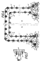
- a chain 48 carrying the carriers 49 runs over the entire area of a cop bridge.
- transfer and delivery points are arranged opposite each other in the area of the lower level, so that both trumes and thus transport directions of the chain 48 are used for the transport of individual carriers 65 with cops 2 or sleeves 66.
- the direction in which the individual carriers are fed or discharged is not rigidly predetermined. The arrangement of the transport system according to the invention is thus extremely flexible.
- the individual carriers 65 are transported along a transport path 58 on a transport belt 59 to the transfer point.
- the conveyor belt 59 is deflected by a pulley 59 '.
- the drive of the conveyor belt is not shown here.
- a guide plate 60 is designed in such a way that it stops the foremost individual carrier 65 with its edge arranged slightly above the upper run of the conveyor belt 59 and holds it ready for engagement by drivers 49 of the chain 48.
- the guide plate 60 and the opposite guide plate 61 then form upper guide surfaces for the individual carriers 65 during of the tipping process.
- the respective individual carrier 65 slides from the stop position through a groove 60 'of the guide plate 60 behind this guide plate.
- the two guide plates 60 and 61 are shaped so that the gap width tapers towards the chain 48 upwards.
- the chain is deflected by sprockets 51 to 56 and in the transfer areas of sprockets 51 ', 57 and 71 and in a delivery area of sprockets 54' and 71 '.
- the sprocket 54 is continuously driven by a motor 75.
- an operating aisle 76 is to be bridged between a spinning machine, to which the transport routes 58 and 63 belong, and a winding machine, to which the transport routes 67 and 73 belong.
- Copes 2 delivered by the spinning machine are transported over the cop bridge to the winding machine side and transferred to the transport path 73.
- Copes, sleeves 66, unwound from the winding machine become the drivers 49 of the chain 48 on the winding machine side fed. These sleeves 66 are transferred with their individual carriers 65 through the lower run of the chain 48 to the spinning machine side and thus to the transport path 63.
- lifting profiles 62 and 62a are arranged on the delivery side of the sleeves 66 to the spinning machine, which lift the individual carriers 65 with the sleeves 66 attached by 90 degrees and transfer them to the upper run of the conveyor belt 64.
- the lifting profile 62a has an oblique side edge through which the individual carriers 65 are additionally displaced laterally during their tilting movement.
- the base formed by the lifting profiles 62 and 62a for the base plates of the individual carriers are increasingly inclined downwards towards the transport path 63, which additionally supports the lateral offset. This measure is particularly necessary if the distance between the drivers 49 is chosen to be small to increase the transport capacity. Particularly when dispensing sleeves 66, a particularly large time offset is not necessary since the sleeves do not have a large diameter.
- the conveyor belt 64 transports out of the image plane. This avoids an additional change in transport direction and it is also possible to dispense with further guide elements along the belt 64.
- the conveyor belt 64 is deflected by a pulley 64 '.
- the drive of the conveyor belt is not shown here.
- the transfer and delivery of the individual carriers 65 on the winding machine side is carried out analogously.
- the transport path 67 forms a conveyor belt 68, which is deflected by a guide roller 68 '.
- guide plates 69 and 70 are provided, the guide plate 70 having a groove 70 '.
- Lifting profiles 72 and 72a are arranged on the delivery side of the cops 2 at the transport path 73.
- the transport path 73 is essentially formed by a conveyor belt 74, which by a Deflection roller 74 'is deflected.
- the drives of the conveyor belts 68 and 74 are also not shown in detail.
- the pallets 65 have a base 65 ', which carries the arbor for the cops 2 or sleeves 66.
- the base 65 ' is connected via spokes 65 ⁇ with a jacket ring 65 ′′′. In this example, only three spokes 65 ⁇ are arranged.
Landscapes
- Replacing, Conveying, And Pick-Finding For Filamentary Materials (AREA)
- Branching, Merging, And Special Transfer Between Conveyors (AREA)
Claims (20)
- Système de transport entre des plans de transport situés à des niveaux différents pour des bobines ou des canettes posées verticalement sur des supports individuels indépendants les uns des autres, comprenant une bande transporteuse qui amène les supports individuels dans un plan de transport, des moyens pour faire basculer jusque dans une position horizontale les bobines ou les canettes qui sont posées verticalement sur cette bande transporteuse, afin de transporter leurs supports individuels sur l'autre plan de transport d'une manière verticale, pour l'essentiel, et un moyen transporteur continu qui vient en prise avec les supports individuels afin de transporter les supports individuels d'une manière verticale, pour l'essentiel, caractérisé par le fait que le moyen transporteur continu (12 ; 34 ; 48) est équipé de taquets d'entraînement (13 ; 26 ; 35 ; 49) distants les uns des autres et entrant en conjugaison des formes avec les supports individuels (1 ; 25 ; 65), par le fait que les moyens de basculement sont constitués par les taquets d'entraînement et par des surfaces de guidage (6, 7, 10, 11 ; 29 ; 60, 61, 69, 70) destinées aux supports individuels, et par le fait que le point de transfert des supports individuels aux taquets d'entraînement est situé sur le brin dirigé vers le haut du moyen transporteur continu qui porte les taquets d'entraînement, le point où les supports individuels sont déchargés par les taquets d'entraînement étant situé sur le brin dirigé vers le bas du moyen transporteur continu.
- Système de transport selon la revendication 1, caractérisé par le fait que les supports individuels (1 ; 25; 65) présentent, à l'intérieur d'une enveloppe annulaire ajourée (1‴ ; 25˝ ; 65‴) de la plaque de base, des évidements (25′) qui sont accessibles depuis le côté inférieur de leurs plaques de base, et par le fait que les taquets d'entraînement (13 ; 26 ; 35 ; 49) qui sont fixés au moyen transporteur continu (12 ; 34 ; 48) sont constitués d'une manière telle qu'ils puissent pénétrer dans les évidements des supports individuels et porter ceux-ci par leur enveloppe annulaire pendant le transport.
- Système de transport selon la revendication 2, caractérisé par le fait que les évidements forment des ouvertures traversantes qui sont ménagées dans la plaque de base des supports individuels (1 ; 65) et qui sont interrompues par des organes de liaison (1′ ; 65˝) analogues à des rayons.
- Système de transport selon l'une des revendications 1 à 3, caractérisé par le fait qu'à l'endroit où les supports individuels (25) sont transférés aux taquets d'entraînement (35), la bande transporteuse (29) qui amène les supports individuels et qui constitue en même temps une surface de guidage pour les supports individuels est inclinée autour d'un axe imaginaire dans une direction de transport d'amenée qui s'étend transversalement par rapport au plan de basculement des bobines (2) ou des canettes (66).
- Système de transport selon l'une des revendications 1 à 4, caractérisé par le fait qu'un arrêt fixe (10 ; 33′ ; 60, 70) est monté à l'endroit où les supports individuels sont transférés aux taquets d'entraînement, et qu'il retient le support individuel qui est le plus en avant dans une position dans laquelle ce support croise la trajectoire des taquets d'entraînement, du moins par l'enveloppe annulaire de sa plaque de base.
- Système de transport selon la revendication 4 ou 5, caractérisé par le fait que des pièces profilées de guidage (6, 7 ; 32, 33, 36, 37 ; 60, 61, 69, 70) sont disposés à l'endroit où les supports individuels (1 ; 25 ; 65) sont transférés aux taquets d'entraînement, afin d'amener à ceux-ci d'une manière sûre les bobines (2) ou les canettes (66), respectivement, et/ou les supports individuels.
- Système de transport selon la revendication 6, caractérisé par le fait que le moyen transporteur continu (12 ; 48) portant les taquets d'entraînement présente, à partir de la position d'arrêt du support individuel à transférer qui est situé le plus en avant, une direction de transport qui amène obliquement vers le haut dans le sens latéral, puis qui se prolonge par un trajet vertical, afin d'obtenir une composante de la direction de transport qui soit transversale par rapport au plan de basculement de la bobine ou de la canette.
- Système de transport selon la revendication 6 ou 7, caractérisé par le fait que le moyen transporteur continu (48) portant les taquets d'entraînement présente une direction de transport qui amène obliquement vers le bas dans le sens latéral vers la position de déchargement des supports individuels, afin d'obtenir une composante de la direction de transport qui soit transversale par rapport au plan de basculement de la bobine ou de la canette.
- Système de transport selon l'une des revendications 5 à 8, caractérisé par le fait que l'une au moins (7) des pièces profilées de guidage est montée élastiquement avec une force de rappel agissant dans la direction du trajet de passage des supports individuels.
- Système de transport selon l'une des revendications 1 à 9, caractérisé par le fait que des profilés de soulèvement (20 ; 47 ; 62, 62a, 72, 72a) sont disposés à l'endroit où les supports individuels sont déchargés, qu'ils font saillie dans le trajet de transport des taquets d'entraînement sans gêner le libre passage de ceux-ci, qu'ils écartent les supports individuels du trajet de transport des taquets d'entraînement, et qu'ils font basculer à nouveau dans la direction de leur position verticale les bobines ou les canettes qui sont posées sur les supports individuels.
- Système de transport selon l'une des revendications 1 à 10, caractérisé par le fait que les profilés de soulèvement (62, 62a, 72, 72a), par leur surface qui sert de surface d'appui aux supports individuels (65), sont inclinés vers le bas d'une manière croissante vers la voie de transport (63, 73) sur laquelle sont déchargés les supports individuels (65).
- Système de transport selon l'une des revendications 10 et 11, caractérisé par le fait que les profilés de soulèvement (62a, 72a) comportent un bord de guidage supplémentaire pour le guidage latéral des supports individuels (65).
- Système de transport selon l'une des revendications 1 à 12, caractérisé par le fait que le long du trajet de transport des taquets d'entraînement (13 ; 35) sont disposés des guidages (10 ; 36) entre lesquels les taquets d'entraînement font saillie et qui servent d'appui aux surfaces de base des supports individuels.
- Système de transport selon l'une des revendications 1 à 13, caractérisé par le fait que les supports individuels (25) sont constitués partiellement par un matériau ferromagnétique, et par le fait que les taquets d'entraînement (26) sont reliés à des aimants (27) qui stabilisent la position des supports individuels pendant le transport des supports individuels par les taquets d'entraînement.
- Système de transport selon l'une des revendications 1 à 13, caractérisé par le fait que les taquets d'entraînement (49) présentent un renflement (49′) analogue à une tête à leur extrémité opposée au moyen transporteur continu (48), et qu'ils portent une plaque d'appui (50) à une distance de ce renflement analogue à une tête qui correspond au moins à la hauteur d'une enveloppe annulaire (65‴), et par le fait que la plaque d'appui (50) est montée tournante sur le taquet d'entraînement (49) et/ou que le taquet d'entraînement (49) est monté tournant dans le moyen transporteur (48).
- Système de transport selon l'une des revendications 10 à 15, caractérisé par le fait que des guidages (11 ; 37) sont disposés le long du trajet de transport des taquets d'entraînement (13 ; 35), et qu'ils surplombent les plaques de base des supports individuels transportés.
- Système de transport selon l'une des revendications 1 à 16, caractérisé par le fait que les taquets d'entraînement (49), sur la partie de leur pourtour par laquelle ils sont en contact avec les supports individuels pendant la totalité du transport, y compris aussi le changement de direction, sont conformés d'une manière telle qu'ils rendent difficile le glissement des supports individuels hors du taquet d'entraînement correspondant.
- Système de transport selon l'une des revendications 1 à 17, caractérisé par le fait qu'en vue de passer au-dessus d'un couloir de passage (76), le moyen transporteur continu (48) qui porte les taquets d'entraînement est guidé successivement sur un trajet vertical, sur un trajet horizontal et à nouveau sur un trajet vertical.
- Système de transport selon l'une des revendications 1 à 17, caractérisé par le fait qu'en vue de passer au-dessus d'un couloir de passage, deux trajets de transport verticaux formés par les taquets d'entraînement sont reliés par une bande transporteuse (23 ; 42) qui s'étend dans un plan supérieur autorisant le libre passage.
- Système de transport selon l'une des revendications 1 à 19, caractérisé par le fait que des endroits de transfert et de déchargement des supports individuels (65) sont à chaque fois disposés au voisinage des rouleaux de déviation (51, 54) situés dans un plan inférieur du moyen transporteur continu (48) qui porte les taquets d'entraînement.
Applications Claiming Priority (2)
| Application Number | Priority Date | Filing Date | Title |
|---|---|---|---|
| DE4015173A DE4015173A1 (de) | 1990-05-11 | 1990-05-11 | Transportsystem fuer auf unabhaengige einzeltraeger senkrecht aufgesetzte spulen oder spulenhuelsen zwischen in der hoehe unterschiedlichen transportebenen |
| DE4015173 | 1990-05-11 |
Publications (3)
| Publication Number | Publication Date |
|---|---|
| EP0455989A2 EP0455989A2 (fr) | 1991-11-13 |
| EP0455989A3 EP0455989A3 (en) | 1991-12-27 |
| EP0455989B1 true EP0455989B1 (fr) | 1994-07-06 |
Family
ID=6406203
Family Applications (1)
| Application Number | Title | Priority Date | Filing Date |
|---|---|---|---|
| EP91105386A Expired - Lifetime EP0455989B1 (fr) | 1990-05-11 | 1991-04-05 | Système de transport entre différents niveaux de hauteur pour des bobines ou des tubes de bobines posées verticalement sur des supports indépendants |
Country Status (4)
| Country | Link |
|---|---|
| US (1) | US5088591A (fr) |
| EP (1) | EP0455989B1 (fr) |
| JP (1) | JPH04226275A (fr) |
| DE (2) | DE4015173A1 (fr) |
Families Citing this family (10)
| Publication number | Priority date | Publication date | Assignee | Title |
|---|---|---|---|---|
| JPH0497770U (fr) * | 1991-01-18 | 1992-08-24 | ||
| DE4224086C2 (de) * | 1992-07-22 | 1999-10-21 | Schlafhorst & Co W | Kopsversorgungsaggregat zur Versorgung einer Spulmaschine mit Kopsen unterschiedlicher Garnpartien |
| DE4236038A1 (de) * | 1992-10-24 | 1994-04-28 | Schlafhorst & Co W | Caddy zum Transport von jeweils einer Textilspule beziehungsweise Textilspulenhülse zu und/oder in einer Textilmaschine |
| DE4336751C2 (de) * | 1993-10-28 | 2002-04-25 | Lfk Gmbh | Verfahren zur automatischen Detektion von festen oder beweglichen Objekten in natürlicher Umgebung einer Echtzeitbildfolge |
| DE19816232A1 (de) * | 1998-04-10 | 1999-10-14 | Schlafhorst & Co W | Transportsystem für Spinnspulen und Spulenhülsen mit einem einen Durchgang überbrückenden Transportweg |
| DE19931982A1 (de) * | 1999-07-09 | 2001-01-11 | Schlafhorst & Co W | Transportvorrichtung für Transportpaletten |
| US8818322B2 (en) | 2006-06-09 | 2014-08-26 | Trapeze Networks, Inc. | Untethered access point mesh system and method |
| JP6472961B2 (ja) * | 2014-08-13 | 2019-02-20 | 日本電子株式会社 | 検体ラック搬送ユニット及び自動分析システム |
| DE102019110294A1 (de) * | 2019-04-18 | 2020-10-22 | Saurer Spinning Solutions Gmbh & Co. Kg | Hülsenspeicher- und -transporteinrichtung für eine Kreuzspulen herstellende Textilmaschine |
| CN112027807B (zh) * | 2020-08-17 | 2022-01-28 | 四川大学 | 纱线管自动换向提升输送装置 |
Family Cites Families (15)
| Publication number | Priority date | Publication date | Assignee | Title |
|---|---|---|---|---|
| DE466153C (de) * | 1926-06-20 | 1928-09-29 | Walter Kuepper | Kettenbahn fuer wagerechte und senkrechte Foerderung |
| GB1170660A (en) * | 1967-07-01 | 1969-11-12 | Giddings & Lewis Fraser Ltd | Magazine for Supplying Bobbins to a Winding Machine |
| DE7301717U (de) * | 1973-01-18 | 1973-05-10 | Licentia Gmbh | Kopsbehälter |
| GB1536931A (en) * | 1975-01-28 | 1978-12-29 | Ntn Toyo Bearing Co Ltd | Pin type transfer apparatus for apertured workpieces |
| JPS5225139A (en) * | 1975-08-18 | 1977-02-24 | Kanebo Ltd | Method of conveying bobbins of textile machine |
| FR2458724A1 (fr) * | 1979-06-13 | 1981-01-02 | Renault | Dispositif de commande de pontage d'un convertisseur de couple hydrodynamique |
| JPS61217480A (ja) * | 1985-03-18 | 1986-09-27 | Murata Mach Ltd | ボビン搬送システム |
| JPS6260774A (ja) * | 1985-09-09 | 1987-03-17 | Murata Mach Ltd | ボビン搬送装置 |
| DE3629561A1 (de) * | 1986-08-30 | 1988-03-03 | Schlafhorst & Co W | Vorrichtung zum konstanthalten der anzahl der zwischen einer spinnmaschine und einer spulmaschine in einem kreislauf befindlichen spulenhuelsen |
| JPS6382285A (ja) * | 1986-09-20 | 1988-04-13 | Murata Mach Ltd | トレイの移送装置 |
| JP2552260B2 (ja) * | 1987-08-29 | 1996-11-06 | 豊和工業株式会社 | 粗糸ボビンの搬送方法 |
| US4842206A (en) * | 1987-12-21 | 1989-06-27 | Murata Kikai Kabushiki Kaisha | Automatic yarn end finding device for a spinning bobbin |
| US5074401A (en) * | 1988-06-16 | 1991-12-24 | Kabushiki Kaisha Toyoda Jidoshokki Seisakusho | Bobbin-carrying apparatus of a combined fine spinning machine and winder |
| JP2680042B2 (ja) * | 1988-06-21 | 1997-11-19 | 株式会社豊田自動織機製作所 | 紡機におけるボビン搬送装置 |
| JP2738968B2 (ja) * | 1988-09-24 | 1998-04-08 | マシーネンファブリク リーター アクチェンゲゼルシャフト | 紡績機械のための無端運搬装置 |
-
1990
- 1990-05-11 DE DE4015173A patent/DE4015173A1/de not_active Withdrawn
-
1991
- 1991-04-05 EP EP91105386A patent/EP0455989B1/fr not_active Expired - Lifetime
- 1991-04-05 DE DE59102101T patent/DE59102101D1/de not_active Expired - Fee Related
- 1991-05-10 JP JP3105369A patent/JPH04226275A/ja active Pending
- 1991-05-13 US US07/699,452 patent/US5088591A/en not_active Expired - Fee Related
Also Published As
| Publication number | Publication date |
|---|---|
| DE4015173A1 (de) | 1991-11-14 |
| US5088591A (en) | 1992-02-18 |
| EP0455989A3 (en) | 1991-12-27 |
| EP0455989A2 (fr) | 1991-11-13 |
| DE59102101D1 (de) | 1994-08-11 |
| JPH04226275A (ja) | 1992-08-14 |
Similar Documents
| Publication | Publication Date | Title |
|---|---|---|
| DE3909786A1 (de) | Vorrichtung zum transportieren von kopsen und huelsen zwischen im verlauf des transportes wechselnden ebenen | |
| DE3334977C2 (fr) | ||
| DE4011797A1 (de) | Transportsystem fuer eine automatische textilmaschine zum gesteuerten fuehren von paletten entlang vorgegebener transportwege | |
| DE2457858C2 (de) | Vorrichtung zum Ausrichten von Kapseln | |
| DE1556693C3 (de) | Vorrichtung zum Ausrichten einer Anzahl von Ampullen in eine regelmäßige Reihenfolge | |
| EP0455989B1 (fr) | Système de transport entre différents niveaux de hauteur pour des bobines ou des tubes de bobines posées verticalement sur des supports indépendants | |
| DE4102028A1 (de) | Foerdereinrichtung | |
| DE4314462C2 (de) | Vorrichtung zum Senkrechtstellen von Dosenzargen | |
| DE2349608C3 (de) | Vorrichtung zum Ausrichten von Behältern | |
| DE3733510A1 (de) | Vorrichtung zum transport von textilspulen | |
| EP1622778B2 (fr) | Systeme et procédé pour inserer des feuilles dans une enveloppe | |
| DE4036214A1 (de) | Doppelspurfoerderanlage fuer bearbeitungs- und/oder montage-anlagen | |
| DD140132A5 (de) | Vorrichtung zum beschicken einer packmaschine mit suesswaren | |
| DE3630670A1 (de) | Spulenfoerdereinrichtung zum transportieren von spinnspulen | |
| DE3433706C2 (fr) | ||
| EP2119658A1 (fr) | Système de transport de tête et d'enveloppe de filage pour des machines textiles fabriquant des bobines croisées | |
| DE3604372A1 (de) | Vorrichtung zum zufuehren von garnkoerpern zu einer automatischen wickelvorrichtung | |
| DE2249043A1 (de) | Vorrichtung zur ausrichtung und zufuhr von flaschen o.dgl | |
| DE3407804C2 (fr) | ||
| DE4124061C2 (de) | Fördervorrichtung mit zwei hochkant gestellten Flachbandförderern | |
| EP0423519B1 (fr) | Transporteur pour le transfert de pots de filature et utilisation du transporteur | |
| DE4025368A1 (de) | Stapelmagazin fuer flaschenkaesten o. dgl. transportkaesten | |
| DE3122849A1 (de) | Einrichtung zum umsetzen von teilen von einer ersten auf eine zweite foerderbahn | |
| DE19624503A1 (de) | Hängefördereinrichtung | |
| DE4113092C2 (de) | Zapfenschlitten-Überführungsvorrichtung an einer Ringspinnmaschine |
Legal Events
| Date | Code | Title | Description |
|---|---|---|---|
| PUAI | Public reference made under article 153(3) epc to a published international application that has entered the european phase |
Free format text: ORIGINAL CODE: 0009012 |
|
| PUAL | Search report despatched |
Free format text: ORIGINAL CODE: 0009013 |
|
| AK | Designated contracting states |
Kind code of ref document: A2 Designated state(s): CH DE FR IT LI |
|
| AK | Designated contracting states |
Kind code of ref document: A3 Designated state(s): CH DE FR IT LI |
|
| 17P | Request for examination filed |
Effective date: 19920206 |
|
| 17Q | First examination report despatched |
Effective date: 19930924 |
|
| ITF | It: translation for a ep patent filed | ||
| GRAA | (expected) grant |
Free format text: ORIGINAL CODE: 0009210 |
|
| AK | Designated contracting states |
Kind code of ref document: B1 Designated state(s): CH DE FR IT LI |
|
| REF | Corresponds to: |
Ref document number: 59102101 Country of ref document: DE Date of ref document: 19940811 |
|
| ET | Fr: translation filed | ||
| PLBE | No opposition filed within time limit |
Free format text: ORIGINAL CODE: 0009261 |
|
| STAA | Information on the status of an ep patent application or granted ep patent |
Free format text: STATUS: NO OPPOSITION FILED WITHIN TIME LIMIT |
|
| 26N | No opposition filed | ||
| PGFP | Annual fee paid to national office [announced via postgrant information from national office to epo] |
Ref country code: FR Payment date: 19990419 Year of fee payment: 9 |
|
| PGFP | Annual fee paid to national office [announced via postgrant information from national office to epo] |
Ref country code: DE Payment date: 19990507 Year of fee payment: 9 Ref country code: CH Payment date: 19990507 Year of fee payment: 9 |
|
| PG25 | Lapsed in a contracting state [announced via postgrant information from national office to epo] |
Ref country code: LI Free format text: LAPSE BECAUSE OF NON-PAYMENT OF DUE FEES Effective date: 20000430 Ref country code: DE Free format text: LAPSE BECAUSE OF NON-PAYMENT OF DUE FEES Effective date: 20000430 Ref country code: CH Free format text: LAPSE BECAUSE OF NON-PAYMENT OF DUE FEES Effective date: 20000430 |
|
| REG | Reference to a national code |
Ref country code: CH Ref legal event code: PL |
|
| PG25 | Lapsed in a contracting state [announced via postgrant information from national office to epo] |
Ref country code: FR Free format text: LAPSE BECAUSE OF NON-PAYMENT OF DUE FEES Effective date: 20001229 |
|
| REG | Reference to a national code |
Ref country code: FR Ref legal event code: ST |
|
| PG25 | Lapsed in a contracting state [announced via postgrant information from national office to epo] |
Ref country code: IT Free format text: LAPSE BECAUSE OF NON-PAYMENT OF DUE FEES;WARNING: LAPSES OF ITALIAN PATENTS WITH EFFECTIVE DATE BEFORE 2007 MAY HAVE OCCURRED AT ANY TIME BEFORE 2007. THE CORRECT EFFECTIVE DATE MAY BE DIFFERENT FROM THE ONE RECORDED. Effective date: 20050405 |