EP0455994A2 - Exzenterantrieb für radialschwingende Walzen, Rollen und Fräsbohrwerkzeuge - Google Patents
Exzenterantrieb für radialschwingende Walzen, Rollen und Fräsbohrwerkzeuge Download PDFInfo
- Publication number
- EP0455994A2 EP0455994A2 EP91105564A EP91105564A EP0455994A2 EP 0455994 A2 EP0455994 A2 EP 0455994A2 EP 91105564 A EP91105564 A EP 91105564A EP 91105564 A EP91105564 A EP 91105564A EP 0455994 A2 EP0455994 A2 EP 0455994A2
- Authority
- EP
- European Patent Office
- Prior art keywords
- sleeve
- eccentric shaft
- tools
- drive
- shaft
- Prior art date
- Legal status (The legal status is an assumption and is not a legal conclusion. Google has not performed a legal analysis and makes no representation as to the accuracy of the status listed.)
- Granted
Links
- 238000005553 drilling Methods 0.000 title claims abstract description 19
- 238000003801 milling Methods 0.000 title claims abstract description 9
- 238000005096 rolling process Methods 0.000 title 1
- 238000000034 method Methods 0.000 claims description 4
- 230000005540 biological transmission Effects 0.000 claims 1
- 230000000903 blocking effect Effects 0.000 claims 1
- 239000011435 rock Substances 0.000 description 3
- 230000004913 activation Effects 0.000 description 2
- 238000005516 engineering process Methods 0.000 description 2
- 230000003213 activating effect Effects 0.000 description 1
- 238000001514 detection method Methods 0.000 description 1
- 230000008030 elimination Effects 0.000 description 1
- 238000003379 elimination reaction Methods 0.000 description 1
- 239000000463 material Substances 0.000 description 1
- 239000002184 metal Substances 0.000 description 1
- 239000004575 stone Substances 0.000 description 1
Images


Classifications
-
- E—FIXED CONSTRUCTIONS
- E21—EARTH OR ROCK DRILLING; MINING
- E21B—EARTH OR ROCK DRILLING; OBTAINING OIL, GAS, WATER, SOLUBLE OR MELTABLE MATERIALS OR A SLURRY OF MINERALS FROM WELLS
- E21B4/00—Drives for drilling, used in the borehole
- E21B4/006—Mechanical motion converting means, e.g. reduction gearings
-
- B—PERFORMING OPERATIONS; TRANSPORTING
- B23—MACHINE TOOLS; METAL-WORKING NOT OTHERWISE PROVIDED FOR
- B23Q—DETAILS, COMPONENTS, OR ACCESSORIES FOR MACHINE TOOLS, e.g. ARRANGEMENTS FOR COPYING OR CONTROLLING; MACHINE TOOLS IN GENERAL CHARACTERISED BY THE CONSTRUCTION OF PARTICULAR DETAILS OR COMPONENTS; COMBINATIONS OR ASSOCIATIONS OF METAL-WORKING MACHINES, NOT DIRECTED TO A PARTICULAR RESULT
- B23Q11/00—Accessories fitted to machine tools for keeping tools or parts of the machine in good working condition or for cooling work; Safety devices specially combined with or arranged in, or specially adapted for use in connection with, machine tools
- B23Q11/0032—Arrangements for preventing or isolating vibrations in parts of the machine
- B23Q11/0035—Arrangements for preventing or isolating vibrations in parts of the machine by adding or adjusting a mass, e.g. counterweights
-
- B—PERFORMING OPERATIONS; TRANSPORTING
- B23—MACHINE TOOLS; METAL-WORKING NOT OTHERWISE PROVIDED FOR
- B23Q—DETAILS, COMPONENTS, OR ACCESSORIES FOR MACHINE TOOLS, e.g. ARRANGEMENTS FOR COPYING OR CONTROLLING; MACHINE TOOLS IN GENERAL CHARACTERISED BY THE CONSTRUCTION OF PARTICULAR DETAILS OR COMPONENTS; COMBINATIONS OR ASSOCIATIONS OF METAL-WORKING MACHINES, NOT DIRECTED TO A PARTICULAR RESULT
- B23Q5/00—Driving or feeding mechanisms; Control arrangements therefor
- B23Q5/02—Driving main working members
- B23Q5/04—Driving main working members rotary shafts, e.g. working-spindles
-
- B—PERFORMING OPERATIONS; TRANSPORTING
- B28—WORKING CEMENT, CLAY, OR STONE
- B28D—WORKING STONE OR STONE-LIKE MATERIALS
- B28D1/00—Working stone or stone-like materials, e.g. brick, concrete or glass, not provided for elsewhere; Machines, devices, tools therefor
- B28D1/18—Working stone or stone-like materials, e.g. brick, concrete or glass, not provided for elsewhere; Machines, devices, tools therefor by milling, e.g. channelling by means of milling tools
-
- E—FIXED CONSTRUCTIONS
- E21—EARTH OR ROCK DRILLING; MINING
- E21B—EARTH OR ROCK DRILLING; OBTAINING OIL, GAS, WATER, SOLUBLE OR MELTABLE MATERIALS OR A SLURRY OF MINERALS FROM WELLS
- E21B10/00—Drill bits
- E21B10/08—Roller bits
- E21B10/086—Roller bits with excentric movement
-
- E—FIXED CONSTRUCTIONS
- E21—EARTH OR ROCK DRILLING; MINING
- E21B—EARTH OR ROCK DRILLING; OBTAINING OIL, GAS, WATER, SOLUBLE OR MELTABLE MATERIALS OR A SLURRY OF MINERALS FROM WELLS
- E21B7/00—Special methods or apparatus for drilling
- E21B7/24—Drilling using vibrating or oscillating means, e.g. out-of-balance masses
Definitions
- roller or milling drilling tools There are various systems for activating roller or milling drilling tools - i.e. to be provided with impact impulses and to let them work. As a result, the required pressure forces are reduced to well below 10% and the drilling / removal rates - especially in hard rock - significantly increased - the use of much lighter machines is possible.
- Activation with known techniques resulted in vibration and energy problems, among others. also extremely hard bumps. These are eliminated by the systems according to the invention with eccentric activation and in particular with dynamic balancing.
- Another special feature of this invention is that the system can be used as a simple roller, as a striking roller drilling tool with its own or third-party drive - as an activated or conventional milling / removing tool; separate protection is required for this.
- FIG. 1 shows a tool-loaded, radially oscillating sleeve, which is rotatably mounted in the bearings 2 on the eccentric 3, with roller drilling tools, milling picks, cutting disks or the like.
- This sleeve can also be hemispherical and also designed be provided on the front with drilling tools so that it also works as a pilot or slot drill - this also requires separate protection.
- 4 are the counterweights that can be adjusted on the eccentric for dynamic balancing.
- 5 is the shaft required for a slowly rotating drive of the sleeve, which is non-positively connected to 1.
- 6 is one of the holders with the bearings 7 in which the other part of the eccentric shaft / sleeve 3 is rotatably mounted.
- this drive shaft can be provided with a cardan joint at the front and rear - for direct motor drive.
- 9 is the drive of the high-speed eccentric shaft - designed as a motor or as shown via (toothed) V-belts.
- the reduction gear claimed as a combination is 10 of the Internal ring gear in which the outer ring gear 11 fastened to the drive shaft 5 runs eccentrically and thereby drives the shaft 5 with a reduction of approximately 20: 1.
- the internal ring gear 10 is provided with a pin 12 which is rotatably mounted in 13; Slowly rotating with it / thus the speed of the sleeve can be reduced with tools braked - increased driven.
- the force retransmission according to the invention with the simultaneous possibility of determining the rotational speed for the sleeve takes place, for example, via the gears 14-18, but is also possible hydraulically, among other things.
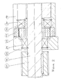
- FIG. 2 another drive system for a driven shaft 26, preferably with two bearings, with sleeve and tools, 19 is the sleeve, which is mounted with the bearings 20 on the eccentric shaft 21 to rotate freely.
- 22 is the slowly rotating inner ring gear attached to the sleeve, which rotates eccentrically around the outer ring gear 23 which is fixed to the frame.
- 24 are the bearings in one of the 25 for the rapidly rotating driven shaft 26 with adjustable and dynamically balanced counterweights inside the sleeve 19 - according to FIG. 1.
- 27 represents a V-belt pulley - but preferably a fast rotating motor is flanged directly.
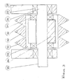
- FIG. 3 shows a roller boring tool that is only eccentrically activated and not externally driven - held in this embodiment on two sides.
- 28 is one of the holders with the bearings 29 for the eccentric shaft 30 with the bearings 31 for the sleeve.
- 32 are, for example, 3 disks with hard metal pins, which are mounted on the eccentrically radially striking sleeve and are balanced by means of the adjustable / dynamically balanced counterweights 34.
- 35 is the driven high-speed eccentric shaft.
- the contact pressure required in the technology according to the invention is only a few 100 kg compared to conventional roller drilling with 10-20 tons of pressure / disc. An enormous advantage.
- roller boring tool automatically rolls on the rock or the like in the opposite direction to the direction of rotation of the crankshaft - thus wears out evenly and / or can thereby drill on the spot.
- a follower lock, ratchet or the like is to be provided to prevent the sleeve from turning quickly in the direction of rotation of the eccentric shaft.
- the outer ring gear which runs in the eccentrically rotating inner ring gear 42.
- the outer ring gear 41 When changing from one amplitude to the other, the outer ring gear 41 must be matched to the inner ring gear 42 - by replacing at least one ring gear. This takes place within minutes - including adjusting the amplitude and rebalancing. Separate protection is also required for this because the amplitude can be optimally adjusted / changed to the material to be processed.
- the drive shaft 37 is arranged centrally in the drive area, does not oscillate and thus does not overload its bearing and can therefore also be driven with a central brake and / or used to transfer force centrally - as an alternative to FIG. 1 with claim 8.
- Corresponding drills with activated drilling tools are only half as complex and heavy as conventional ones - and drill twice as fast, especially in hard rock, and also have less wear on the drilling tools due to their smooth running.
Landscapes
- Engineering & Computer Science (AREA)
- Mining & Mineral Resources (AREA)
- Geology (AREA)
- Life Sciences & Earth Sciences (AREA)
- Mechanical Engineering (AREA)
- General Life Sciences & Earth Sciences (AREA)
- Fluid Mechanics (AREA)
- Environmental & Geological Engineering (AREA)
- Physics & Mathematics (AREA)
- Geochemistry & Mineralogy (AREA)
- Earth Drilling (AREA)
- Processing Of Stones Or Stones Resemblance Materials (AREA)
- Placing Or Removing Of Piles Or Sheet Piles, Or Accessories Thereof (AREA)
- Finish Polishing, Edge Sharpening, And Grinding By Specific Grinding Devices (AREA)
- Apparatuses For Generation Of Mechanical Vibrations (AREA)
- Pharmaceuticals Containing Other Organic And Inorganic Compounds (AREA)
- Perforating, Stamping-Out Or Severing By Means Other Than Cutting (AREA)
Abstract
Description
- Es gibt diverse Systeme Rollen- oder Fräsbohrwerkzeuge zu aktivieren - d.h. mit Schlagimpulsen zu versehen und schlagend arbeiten zu lassen. Hierdurch werden die erforderlichen Andruckkräfte auf weit unter 10% reduziert und die Bohr- / Abtragleistungen - besonders im Hartgestein - erheblich erhöht - ist die Verwendung wesentlich leichterer Maschinen möglich.
- Beim Aktivieren mit bekannten Techniken ergaben sich Schwingungs- und Energieprobleme u.a. auch extrem harte Prellschläge. Durch die erfindungsgemäßen Systeme mit Exzenteraktivierung und insbesondere mit dynamischer Auswuchtung werden diese eliminiert. Eine Besonderheit dieser Erfindung liegt außerdem darin, das System als einfaches Rollen-, als schlagendes Rollenbohrwerkzeug mit Eigen- oder Fremdantrieb - als aktiviertes oder konventionelles Fräsbohr- / Abtragwerkzeug zum Einsatz bringen zu können; hierfür wird gesonderter Schutz beansprucht.
- Beispiel: Die Exzenterwelle wird mit 3.000 U/min angetrieben, der Exzenter hat eine Amplitude von 5 mm und die Hülse resp. das Werkzeug läuft 30 : 1 untersetzt radial schlagend mit nur 100 U/min; die Gegengewichte sind so angeordnet, bemessen und eingestellt, daß sie die Hülse mit Werkzeugen dynamisch auswuchten.
- In jeweils nur einem Ausführungsbeispiel zeigt die Figur 1 in 1 eine mit Werkzeugen bestückte - in den Lagern 2 auf dem Exzenter 3 drehend gelagerte radial schwingende Hülse mit Rollenbohrwerkzeugen, Fräspicken, Schneidscheiben oder dgl. Diese Hülse kann auch halb / -kugelig ausgebildet und auch an ihrer Frontseite mit Bohrwerkzeugen versehen sein, sodaß sie auch als Pilot- oder Schlitzbohrer arbeitet - hierfür wird ebenfalls gesonderter Schutz beansprucht. 4 sind die am Exzenter justierbaren Gegengewichte zur dynamischen Auswuchtung. 5 ist die für einen langsam drehenden Antrieb der Hülse erforderliche Welle, die mit 1 kraftschlüssig verbunden ist. 6 ist einer der Halter mit den Lagern 7 in denen der andere Teil der Exzenterwelle / Hülse 3 drehend gelagert ist. 8 sind die bei dieser Ausführung erforderlichen Lager für die Antriebswelle 5. Diese Antriebswelle kann aber vorne und hinten mit ein Kardangelenk versehen sein - für direkten motorischen Antrieb. 9 ist der Antrieb der schnellaufenden Exzenterwelle - als Motor ausgebildet oder wie dargestellt über (Zahn-) Keilriemen. In einer gesonderten Ausführung als Kombination beanspruchtes Untersetzungsgetriebe ist 10 der Innenzahnkranz in welchem der an der Antriebswelle 5 befestigte Außenzahnkranz 11 exzentrisch abläuft und dadurch die Welle 5 in etwa 20 : 1 untersetzt antreibt. in einer besonders beanspruchten Ausführung ist der Innenzahnkranz 10 mit einem Zapfen 12 versehen, der in 13 drehend gelagert ist; langsam mitdrehend kann somit/damit die Drehzahl der Hülse mit Werkzeugen gebremst reduziert werden - angetrieben erhöht werden. Die erfindungsgemäße Kraftrückübertragung mit gleichzeitiger Möglichkeit einer Drehzahlbestimmung für die Hülse erfolgt beispielsweise über die Zahnräder 14 - 18, ist aber u.a. auch hydraulisch möglich.
- In der Figur 2, einem anderen Antriebssystem für eine vorzugsweise zweiseitig gelagerte angetriebene Welle 26 mit Hülse und Werkzeugen ist 19 die Hülse, die mit den Lagern 20 auf der Exzenterwelle 21 frei drehend gelagert ist. 22 ist bei dieser Ausführung der langsam drehende an der Hülse befestigte Innenzahnkranz, der um den gestellfest angeordneten Außenzahnkranz 23 exzentrisch rotiert. 24 sind die Lager in einem der 25 für die schnell drehende angetriebene Welle 26 mit justier- und dynamisch auswuchtbaren Kontergewichten im Inneren der Hülse 19 - gemäß Figur 1. 27 stellt eine Keilriemenscheibe dar - vorzugsweise wird aber ein schnelldrehender Motor direkt angeflauscht.
- In Figur 3 ist ein über 35 nur exzenteraktiviertes nicht fremd angetriebenes Rollenbohrwerkzeug dargestellt - in dieser Ausführung zweiseitig gehalten. 28 ist einer der Halter mit den Lagern 29 für die Exzenterwelle 30 mit den Lagern 31 für die Hülse. 32 sind beispielsweise 3 Disken mit Hartmetallstiften, die auf der Exzentrisch radial schlagenden Hülse montiert sind und über die justierbaren / dynamisch auswuchtbaren Gegengewichte 34 ausgewuchtet werden. 35 ist die angetriebene schnellaufende Exzenterwelle. Um gleiche Bohrleistungen im Hartgetein zu erzielen, liegt der bei der erfindungsgemäßen Technik erforderliche Anpressdruck bei nur wenigen 100 kg im Verglich zum konventionellen Rollenbohren mit 10 - 20 Tonnen Andruck / Diske. Ein enormer Vorteil. Außerdem rollt das Roolenbohrwerkzeug bei dieser erfindungsgemäßen Technik selbständig langsam rotierend gegenläufig zur Kurbelwellendrehrichtung auf dem Gestein oder dgl. ab - verschleißt damit gleichmäßig und/oder kann dadurch auf der Stelle bohren. Eine Mitlaufsperre, Ratsche oder dgl. ist vorzusehen, um das schnelle Mitdrehen der Hülse in Drehrichtung der Exzenterwelle zu verhindern.
- In Figur 4 - einer speziellen Bauart - für die gesonderter Schutz dafür beansprucht wird, daß sich das Untersetzungsgetriebe am äußeren freien Ende der Hülse in der Hülse befindet - und entsprechend Anspruch 10 dafür, daß mittels einer exzentrischen dreh- und feststellbaren dünnwandigen Hülse 39 die Ampltude festgelegt und z.B. zum konventionellen Fräsen bis auf 0 gestellt werden kann - bei kraftschlüssiger Verbindung der Welle 37 mit der Hülse 38 z.B. mit einem Stift 36. 39 ist die dünnwandige dreh- und feststellbare Hülse zur wahlweisen Einstellung der Amplitude von max bis 0; das Feststellen kann von außen über 40 erfolgen. 41 sind gemäß Figur 1 der Außenzahnkranz, der in dem exzentrisch rotierenden Innenzahnkranz 42 abläuft. Beim Umstellen von einer Amplitude auf die andere müssen der Außenzahnkranz 41 auf den Innenzahnkranz 42 abgestimmt werden - durch Auswechseln wenigstens eines Zahnkranzes. Dies geschieht innerhalb von Minuten - inkl. Verstellung der Amplitude und Neuauswuchtung. Hierfür wird auch insofern gesonderter Schutz bansprucht, weil damit die Amplitude optimal auf das jeweils zu bearbeitende Material ein- / umgestellt werden kann. Die Antriebswelle 37 ist bei dieser besonders vorteilhaften und erfindungsgemäßen Bauart im Antriebsbereich zentrisch angeordnet, schwingt nicht und überbelastet damit ihre Lagerung nicht und kann somit auch zentrisch gebremst angetrieben werden und / oder zentrisch kraftrückübertragend genutzt werden - als Alternative zur Figur 1 mit Anspruch 8.
- Besonderer Schutz wird gemäß Anspruch 2 auch dafür beansprucht, die Bauart gemäß Figur 4 Anspruch 2 als einseitig gehaltenes fliegend gelagertes, selbständig drehendes Rollenbohrwerkzeug (mit Disken oder dgl.) fungieren zu lassen; dies geschieht unter Wegfall der Welle 37 und Zahnräder 41 und 42 - es bringt u.a. den Vorteil der schnelleren Auswechselbarkeit der eigentliche Bohrwerkzeuge.
- Für das Verfahren, diese erfindungsgemäße Technik mit nicht nur aktivierten sondern auch angetriebenen Rollenbohrwerkzeugen zum Eigenantrieb von Pilot-, Großloch-, Schacht- und Tunnelbohrköpfen einzusetzen, wird gesonderter Schutz beansprucht - vorzugsweise unter Verwendung eines Hilfsantriebes, um das kontinuierliche Drehen des Bohrkopfes bei Klüften etc. zu gewährleisten.
- Entsprechende Bohrmaschinen mit aktivierten Bohrwerkzeugen sind nur noch halb so aufwendig und schwer wie konventionelle - und bohren besonders im Hartgestein doppelt so schnell und haben auch durch ihren ruhigen Lauf geringeren Verschleiß an den Bohrwerkzeugen.
Claims (10)
- Exzenteraktivierte radial schwingende rotierende Bohrwerkzeuge mit getrenntem Antrieb für die schnelldrehende Exzenterwelle und eine langsam laufende / ablaufende Hülse mit Werkzeugen dadurch gekennzeichnet, daß das oder die an der Exzenterwelle befestigten justierbaren Gegengewichte zur dynamischen Auswuchtung im Zentrum der auf der Exzenterwelle drehend gelagerten Hülse rotieren.
- nach 1 gekennzeichnet durch Eigenantrieb / Selbstdrehen einer mit Rollenbohrwerkzeugen ausgebildeten und fungierenden Hülse.
- nach 1 gekennzeichnet durch eine mit Fräswerkzeugen versehen und fungierende Hülse.
- nach 1 bis 3 gekennzeichnet durch Fremdantrieb der Hülse mit Werkzeugen.
- nach 1 bis 4 gekennzeichnet durch einseitige Halterung / Lagerung der Exzenterwelle mit Hülse und gleichseitigem Antrieb der Hülse und Exzenterwelle.
- nach 1 bis 5 dadurch gekennzeichnet, daß eine freidrehende Welle durch die Exzenterwelle zum äußeren Ende der Hülse geführt wird.
- nach 1 bis 6 gekennzeichnet durch die Kombination mit einem Untersetzungsgetriebe, das aus einem Zahnrad besteht das in einem gehaltenen Innenzahnkranz exzentrisch abläuft resp. aus einem Innenzahnkranz, der um ein gehaltenes Zahnrad exzentrisch abläuft.
- nach 6 und 7 dadurch gekennzeichnet, diese Welle an ihrem äußeren freien Ende zu blockieren - die Drehzahl der hiermit angetriebenen Hülse über eine Bremse zu reduzieren - oder über einen Motor zu erhöhen.
- nach 8 gekennzeichnet durch den Verfahrensanspruch der mechanischen / hydraulischen Kraftrückübertragung vom Untersetzungsgetriebe auf die Exzenterwelle bei gleichzeitiger Wähl- / Einstellbarkeit der jeweils optimalen Drehzahl für das Fräs- oder Rollenbohrwerkzeug.
- nach 1 bis 9 gekennzeichnet durch Einstellbarkeit der Amplitude bis auf 0.
Applications Claiming Priority (2)
| Application Number | Priority Date | Filing Date | Title |
|---|---|---|---|
| CH1205/90 | 1990-04-09 | ||
| CH1205/90A CH684786A5 (de) | 1990-04-09 | 1990-04-09 | Exzenteraktivierte radial schwingende rotierende Werkzeughalter. |
Publications (3)
| Publication Number | Publication Date |
|---|---|
| EP0455994A2 true EP0455994A2 (de) | 1991-11-13 |
| EP0455994A3 EP0455994A3 (en) | 1992-01-02 |
| EP0455994B1 EP0455994B1 (de) | 1997-08-27 |
Family
ID=4204962
Family Applications (1)
| Application Number | Title | Priority Date | Filing Date |
|---|---|---|---|
| EP91105564A Expired - Lifetime EP0455994B1 (de) | 1990-04-09 | 1991-04-09 | Exzenterantrieb für radialschwingende Walzen, Rollen und Fräsbohrwerkzeuge |
Country Status (8)
| Country | Link |
|---|---|
| US (1) | US5190353A (de) |
| EP (1) | EP0455994B1 (de) |
| AT (1) | ATE157424T1 (de) |
| AU (1) | AU650008B2 (de) |
| CA (1) | CA2040071C (de) |
| CH (1) | CH684786A5 (de) |
| DE (2) | DE9015579U1 (de) |
| ZA (1) | ZA912567B (de) |
Cited By (2)
| Publication number | Priority date | Publication date | Assignee | Title |
|---|---|---|---|---|
| EP0898051A1 (de) | 1997-08-18 | 1999-02-24 | Bechem, Hannelore | Kombination konventioneller Schlitzwerkzeuge mit exzenteraktivierten Fräsbohrwerkzeugen |
| US6774564B1 (en) | 1999-06-23 | 2004-08-10 | Patent-Treuhand-Gesellshaft Fuer Elektrische Gluehlampen | Method for mounting the base of an electric lamp |
Families Citing this family (21)
| Publication number | Priority date | Publication date | Assignee | Title |
|---|---|---|---|---|
| CH688815A5 (de) * | 1992-10-14 | 1998-04-15 | Bechem Hannelore | Aggregat zum Bohren, Fräsen, Schlitzen und Verdichten von Materialien. |
| CH689546A5 (de) * | 1994-07-13 | 1999-06-15 | Bechem Hannelore | Ueber Exzenter schlagend arbeitende Werkzeuge zum Bearbeiten von Materialien. |
| US5685615A (en) * | 1996-01-17 | 1997-11-11 | Bechem; Klaus | Eccentrically driven percussive tools for treating materials |
| AU733847B2 (en) * | 1996-01-17 | 2001-05-31 | Hannelore Bechem | Eccentrically driven percussive tools for treating materials |
| AU745927B2 (en) * | 1997-08-18 | 2002-04-11 | Hannelore Bechem | A process for producing slots, grooves and the like |
| US6857706B2 (en) | 2001-12-10 | 2005-02-22 | Placer Dome Technical Services Limited | Mining method for steeply dipping ore bodies |
| US7695071B2 (en) * | 2002-10-15 | 2010-04-13 | Minister Of Natural Resources | Automated excavation machine |
| US7479975B2 (en) * | 2004-03-26 | 2009-01-20 | Alps Electric Co., Ltd. | Printer |
| US7192093B2 (en) * | 2004-04-23 | 2007-03-20 | Placer Dome Technical Services Limited | Excavation apparatus and method |
| US7434890B2 (en) * | 2005-03-23 | 2008-10-14 | Boart Longyear Inc. | Vibratory milling machine having linear reciprocating motion |
| US8079647B2 (en) * | 2005-03-23 | 2011-12-20 | Longyear Tm, Inc. | Vibratory milling machine having linear reciprocating motion |
| US7490911B2 (en) | 2005-06-18 | 2009-02-17 | Dbt Gmbh | Drive device for rotating and oscillating a tool, and a compatible tool for mining |
| US7546883B1 (en) | 2006-05-15 | 2009-06-16 | Astec Industries, Inc. | Vibratory plow |
| PL3656977T3 (pl) * | 2012-09-14 | 2024-03-04 | Joy Global Underground Mining Llc | Głowica wrębiarki do maszyny górniczej |
| FI3408499T3 (fi) | 2016-01-27 | 2023-06-05 | Joy Global Underground Mining Llc | Useilla leikkuripäillä varustettu kaivoskone |
| PE20190493A1 (es) | 2016-08-19 | 2019-04-09 | Joy Global Underground Mining Llc | Maquina de mineria con brazo mecanico de articulacion y sistema de manipulacion de material independiente |
| US11391149B2 (en) | 2016-08-19 | 2022-07-19 | Joy Global Underground Mining Llc | Mining machine with articulating boom and independent material handling system |
| US10738608B2 (en) | 2016-08-19 | 2020-08-11 | Joy Global Underground Mining Llc | Cutting device and support for same |
| AU2017330401B2 (en) | 2016-09-23 | 2023-02-09 | Joy Global Underground Mining Llc | Machine supporting rock cutting device |
| DE102018108686B3 (de) | 2018-04-12 | 2019-08-14 | Technische Universität Bergakademie Freiberg | Vorrichtungen und Verfahren zur Schlagbelastungsübertragung auf Diskenmeißel von Gesteinsbearbeitungsmaschinen |
| FI3814608T3 (fi) | 2018-07-25 | 2025-01-22 | Joy Global Underground Mining Llc | Kokoonpano kallioleikkausta varten |
Family Cites Families (9)
| Publication number | Priority date | Publication date | Assignee | Title |
|---|---|---|---|---|
| DE2159351C3 (de) * | 1971-11-30 | 1981-02-26 | Salzgitter Maschinen Und Anlagen Ag, 3320 Salzgitter | Bohrgerät mit wenigstens einer mit einem Unwuchtvibrator versehenen Schneidrolle |
| DE3481821D1 (de) * | 1983-05-26 | 1990-05-10 | Nippon Telegraph & Telephone | Geraet zur schwingungserzeugung. |
| US4736987A (en) * | 1986-06-09 | 1988-04-12 | General Mining Union Corporation Limited | Rock cutting assembly |
| US4815543A (en) * | 1986-06-09 | 1989-03-28 | General Mining Union Corporation Limited | Activated rock cutting assembly |
| SU1442627A1 (ru) * | 1986-10-24 | 1988-12-07 | В. Л. Гой | Устройство дл бурени квадратных шурфов |
| CH675387A5 (de) * | 1987-06-29 | 1990-09-28 | Bechem Hannelore | |
| CH678706A5 (de) * | 1987-08-31 | 1991-10-31 | Bechem Hannelore | |
| CH677890A5 (de) * | 1987-12-30 | 1991-07-15 | Hannelore Bechem | Exzenterantrieb fuer bohrwerkzeuge. |
| GB8818024D0 (en) * | 1988-07-28 | 1988-09-01 | British Petroleum Co Plc | Variable mass rotor |
-
1990
- 1990-04-09 CH CH1205/90A patent/CH684786A5/de not_active IP Right Cessation
- 1990-11-14 DE DE9015579U patent/DE9015579U1/de not_active Expired - Lifetime
-
1991
- 1991-04-08 US US07/681,681 patent/US5190353A/en not_active Expired - Lifetime
- 1991-04-08 ZA ZA912567A patent/ZA912567B/xx unknown
- 1991-04-09 AT AT91105564T patent/ATE157424T1/de not_active IP Right Cessation
- 1991-04-09 EP EP91105564A patent/EP0455994B1/de not_active Expired - Lifetime
- 1991-04-09 AU AU74228/91A patent/AU650008B2/en not_active Expired
- 1991-04-09 DE DE59108833T patent/DE59108833D1/de not_active Expired - Lifetime
- 1991-04-09 CA CA002040071A patent/CA2040071C/en not_active Expired - Lifetime
Cited By (3)
| Publication number | Priority date | Publication date | Assignee | Title |
|---|---|---|---|---|
| EP0898051A1 (de) | 1997-08-18 | 1999-02-24 | Bechem, Hannelore | Kombination konventioneller Schlitzwerkzeuge mit exzenteraktivierten Fräsbohrwerkzeugen |
| US6139477A (en) * | 1997-08-18 | 2000-10-31 | Bechem; Ulrich | Process for producing slots, grooves, and planar excavations |
| US6774564B1 (en) | 1999-06-23 | 2004-08-10 | Patent-Treuhand-Gesellshaft Fuer Elektrische Gluehlampen | Method for mounting the base of an electric lamp |
Also Published As
| Publication number | Publication date |
|---|---|
| ATE157424T1 (de) | 1997-09-15 |
| AU7422891A (en) | 1991-10-10 |
| EP0455994A3 (en) | 1992-01-02 |
| DE9015579U1 (de) | 1991-08-08 |
| DE59108833D1 (de) | 1997-10-02 |
| CH684786A5 (de) | 1994-12-30 |
| EP0455994B1 (de) | 1997-08-27 |
| ZA912567B (en) | 1992-06-24 |
| US5190353A (en) | 1993-03-02 |
| CA2040071A1 (en) | 1991-10-10 |
| CA2040071C (en) | 2004-11-23 |
| AU650008B2 (en) | 1994-06-09 |
Similar Documents
| Publication | Publication Date | Title |
|---|---|---|
| EP0455994A2 (de) | Exzenterantrieb für radialschwingende Walzen, Rollen und Fräsbohrwerkzeuge | |
| EP1841949B1 (de) | Vorrichtung für die fräsende bearbeitung von gestein und anderen materialien sowie verfahren zum fräsen von gestein oder dgl. unter verwendung der vorrichtung | |
| EP0329915B1 (de) | Exzentrisch angeordnete, drehend gelagerte Welle für Bohrwerkzeuge | |
| EP2057348B1 (de) | Verfahren und vorrichtung fur die fräsende bearbeitung von materialen | |
| DE3713544A1 (de) | Angetriebener erdbohrer und verfahren zum erdbohren | |
| DE2822501A1 (de) | Gesteinsschneidewerkzeug | |
| DE10205124C1 (de) | Gewinnungsvorrichtung | |
| EP2597249A1 (de) | Bohrgerät und Verfahren zum Erstellen einer vertikalen Bohrung | |
| DE2439063A1 (de) | Vorrichtung zum grubenbau | |
| EP0763410A2 (de) | Fahrbares Oberflächenbearbeitungsgerät | |
| DE4332113A1 (de) | Bohrgerät für Bohrungen im Erdreich mit unterschiedlichen Bodenklassen | |
| EP1734224B1 (de) | Antriebsvorrichtung für rotierende, mit Oszillationsüberlagerung arbeitende Werkzeuge und Werkzeug hiermit | |
| DE3301671C2 (de) | ||
| CH672659A5 (de) | ||
| DE2139829A1 (de) | Anordnung zum trockenschmieren von rotierenden spanenden werkzeugen | |
| DE10002213A1 (de) | Optimierung exzenterschlagüberlagerter gegengewuchteter Werkzeuge | |
| EP0330683A1 (de) | Schneid-/rollenmeissel | |
| CH689546A5 (de) | Ueber Exzenter schlagend arbeitende Werkzeuge zum Bearbeiten von Materialien. | |
| DE4036193A1 (de) | Exzenterantrieb fuer radial schwingende walzen-, rollen- und fraesbohrwerkzeuge | |
| DE2448753C2 (de) | Schneidkopf fur Vortriebs- und Gewinnungsmaschinen im Berg- und Tunnelbau | |
| EP0203123B1 (de) | Radial schlagendes rollen-/fräs-bohrwerkzeug auf einem angetriebenen rotierenden exzenter drehend gelagert | |
| WO2004013449A2 (de) | Vorrichtung zum vortreiben von bohrungen im erdreich | |
| CH688815A5 (de) | Aggregat zum Bohren, Fräsen, Schlitzen und Verdichten von Materialien. | |
| DE2430519A1 (de) | Steinbrechvorrichtung | |
| WO1989001837A1 (fr) | Rouleaux, billes rotatifs ou similaires radialement percutants pour le deblayage/fraisage de rochers ou d'autres materiaux |
Legal Events
| Date | Code | Title | Description |
|---|---|---|---|
| PUAI | Public reference made under article 153(3) epc to a published international application that has entered the european phase |
Free format text: ORIGINAL CODE: 0009012 |
|
| AK | Designated contracting states |
Kind code of ref document: A2 Designated state(s): AT DE ES FR GB IT LU NL SE |
|
| PUAL | Search report despatched |
Free format text: ORIGINAL CODE: 0009013 |
|
| RBV | Designated contracting states (corrected) |
Designated state(s): AT DE FR GB IT SE |
|
| AK | Designated contracting states |
Kind code of ref document: A3 Designated state(s): AT DE ES FR GB IT LU NL SE |
|
| 17P | Request for examination filed |
Effective date: 19920527 |
|
| 17Q | First examination report despatched |
Effective date: 19930421 |
|
| GRAG | Despatch of communication of intention to grant |
Free format text: ORIGINAL CODE: EPIDOS AGRA |
|
| GRAH | Despatch of communication of intention to grant a patent |
Free format text: ORIGINAL CODE: EPIDOS IGRA |
|
| GRAH | Despatch of communication of intention to grant a patent |
Free format text: ORIGINAL CODE: EPIDOS IGRA |
|
| GRAH | Despatch of communication of intention to grant a patent |
Free format text: ORIGINAL CODE: EPIDOS IGRA |
|
| GRAA | (expected) grant |
Free format text: ORIGINAL CODE: 0009210 |
|
| AK | Designated contracting states |
Kind code of ref document: B1 Designated state(s): AT DE FR GB IT SE |
|
| REF | Corresponds to: |
Ref document number: 157424 Country of ref document: AT Date of ref document: 19970915 Kind code of ref document: T |
|
| REF | Corresponds to: |
Ref document number: 59108833 Country of ref document: DE Date of ref document: 19971002 |
|
| ITF | It: translation for a ep patent filed | ||
| ET | Fr: translation filed | ||
| GBT | Gb: translation of ep patent filed (gb section 77(6)(a)/1977) |
Effective date: 19980122 |
|
| PLBE | No opposition filed within time limit |
Free format text: ORIGINAL CODE: 0009261 |
|
| STAA | Information on the status of an ep patent application or granted ep patent |
Free format text: STATUS: NO OPPOSITION FILED WITHIN TIME LIMIT |
|
| 26N | No opposition filed | ||
| REG | Reference to a national code |
Ref country code: GB Ref legal event code: IF02 |
|
| PGFP | Annual fee paid to national office [announced via postgrant information from national office to epo] |
Ref country code: GB Payment date: 20100323 Year of fee payment: 20 |
|
| PGFP | Annual fee paid to national office [announced via postgrant information from national office to epo] |
Ref country code: FR Payment date: 20100423 Year of fee payment: 20 |
|
| PGFP | Annual fee paid to national office [announced via postgrant information from national office to epo] |
Ref country code: AT Payment date: 20100429 Year of fee payment: 20 Ref country code: DE Payment date: 20100525 Year of fee payment: 20 Ref country code: IT Payment date: 20100428 Year of fee payment: 20 |
|
| PGFP | Annual fee paid to national office [announced via postgrant information from national office to epo] |
Ref country code: SE Payment date: 20100423 Year of fee payment: 20 |
|
| REG | Reference to a national code |
Ref country code: DE Ref legal event code: R071 Ref document number: 59108833 Country of ref document: DE |
|
| REG | Reference to a national code |
Ref country code: GB Ref legal event code: PE20 Expiry date: 20110408 |
|
| PG25 | Lapsed in a contracting state [announced via postgrant information from national office to epo] |
Ref country code: GB Free format text: LAPSE BECAUSE OF EXPIRATION OF PROTECTION Effective date: 20110408 |
|
| PG25 | Lapsed in a contracting state [announced via postgrant information from national office to epo] |
Ref country code: DE Free format text: LAPSE BECAUSE OF EXPIRATION OF PROTECTION Effective date: 20110409 |