EP0456008A1 - Cadre de pied pour un meuble pliant et articulation pour ce cadre - Google Patents
Cadre de pied pour un meuble pliant et articulation pour ce cadre Download PDFInfo
- Publication number
- EP0456008A1 EP0456008A1 EP91106012A EP91106012A EP0456008A1 EP 0456008 A1 EP0456008 A1 EP 0456008A1 EP 91106012 A EP91106012 A EP 91106012A EP 91106012 A EP91106012 A EP 91106012A EP 0456008 A1 EP0456008 A1 EP 0456008A1
- Authority
- EP
- European Patent Office
- Prior art keywords
- joint
- pin
- leg
- legs
- pin hole
- Prior art date
- Legal status (The legal status is an assumption and is not a legal conclusion. Google has not performed a legal analysis and makes no representation as to the accuracy of the status listed.)
- Granted
Links
- 241000309551 Arthraxon hispidus Species 0.000 claims abstract description 14
- 210000000078 claw Anatomy 0.000 claims description 6
- 229920003023 plastic Polymers 0.000 description 5
- 239000004033 plastic Substances 0.000 description 5
- 210000001364 upper extremity Anatomy 0.000 description 5
- 239000002184 metal Substances 0.000 description 2
- 239000007787 solid Substances 0.000 description 2
- 208000034656 Contusions Diseases 0.000 description 1
- 208000027418 Wounds and injury Diseases 0.000 description 1
- 230000006378 damage Effects 0.000 description 1
- 230000007423 decrease Effects 0.000 description 1
- 230000000694 effects Effects 0.000 description 1
- 208000014674 injury Diseases 0.000 description 1
- 238000004519 manufacturing process Methods 0.000 description 1
- 239000000463 material Substances 0.000 description 1
Images



Classifications
-
- A—HUMAN NECESSITIES
- A47—FURNITURE; DOMESTIC ARTICLES OR APPLIANCES; COFFEE MILLS; SPICE MILLS; SUCTION CLEANERS IN GENERAL
- A47C—CHAIRS; SOFAS; BEDS
- A47C1/00—Chairs adapted for special purposes
- A47C1/14—Beach chairs ; Chairs for outdoor use, e.g. chairs for relaxation or sun-tanning
- A47C1/143—Chaise lounges
-
- A—HUMAN NECESSITIES
- A47—FURNITURE; DOMESTIC ARTICLES OR APPLIANCES; COFFEE MILLS; SPICE MILLS; SUCTION CLEANERS IN GENERAL
- A47C—CHAIRS; SOFAS; BEDS
- A47C4/00—Foldable, collapsible or dismountable chairs
- A47C4/04—Folding chairs with inflexible seats
-
- A—HUMAN NECESSITIES
- A47—FURNITURE; DOMESTIC ARTICLES OR APPLIANCES; COFFEE MILLS; SPICE MILLS; SUCTION CLEANERS IN GENERAL
- A47C—CHAIRS; SOFAS; BEDS
- A47C4/00—Foldable, collapsible or dismountable chairs
- A47C4/04—Folding chairs with inflexible seats
- A47C4/08—Folding chairs with inflexible seats having a frame made of wood or plastics
- A47C4/10—Folding chairs with inflexible seats having a frame made of wood or plastics with legs pivotably connected to seat or underframe
- A47C4/14—Folding chairs with inflexible seats having a frame made of wood or plastics with legs pivotably connected to seat or underframe with cross legs
-
- A—HUMAN NECESSITIES
- A47—FURNITURE; DOMESTIC ARTICLES OR APPLIANCES; COFFEE MILLS; SPICE MILLS; SUCTION CLEANERS IN GENERAL
- A47C—CHAIRS; SOFAS; BEDS
- A47C7/00—Parts, details, or accessories of chairs or stools
- A47C7/002—Chair or stool bases
- A47C7/006—Chair or stool bases with castors
Definitions
- the invention relates to a leg frame for a folding piece of furniture with at least one pair of legs, the two rows of which are connected in a V arrangement at their upper ends via a joint which can be spread and folded, the joint having a joint head connected to one leg with a joint pin and one with the other leg connected joint socket with a mortise.
- the invention further relates to a joint part which is intended to make two legs of a leg frame for a folding piece of furniture in a V-shaped arrangement expandable and foldable.
- Leg frames or joint parts of the type mentioned at the outset are known. They serve to make folding furniture, such as camping, garden and patio chairs or loungers, so that these pieces of furniture can be folded to a minimum and take up little space in this state. It has been found to be disadvantageous that with very closely spaced legs of a pair of legs that are brought together in one joint, the risk of injury and bruising is very great, since the operator gets his fingers between the two legs. This creates a dangerous situation with folding furniture that is equipped with known leg frames and joints Scherstelle because the legs move towards each other until they lie on top of each other. It is therefore usually avoided that the joint is equipped so that the two legs are completely on top of each other. Because of this scope, the volume of the folded furniture is 15 to 25% larger than that of a piece of furniture that does not have this safety margin.
- leg frame or a joint part for garden furniture in which no such dangerous situation arises, even if it should be possible in principle to fold the legs one on top of the other. Nevertheless, the leg frame should not have any dangerous insecurities in a spread standing position, that is, it should have no undesirable play in the joint.
- the pin hole is designed as a pin hole extending transversely to the bisector of the spreading angle, and a control member is provided in the region of the joint, which at the extreme spread position of the legs has the joint pin at one end of the mortise.
- the invention is also implemented by a corresponding joint part.
- a pin hole is accordingly provided which allows the pin a certain play, so that in the folded state the two legs can be pulled apart by the effective length of the pin hole and pressed together again. In any case, it prevents the operator's fingers from getting caught between the legs. If the leg frame is spread out, a control element comes into action at a certain spreading angle which is smaller than the final spreading angle, that pushes the two legs apart or pulls together in the joint area, at least in such a way that at the end point of the spreading movement the pin comes to rest in one or the other extreme position of the pin hole and is fixed there.
- the pin hole is preferably a circular ring section which is rounded at its ends and which is concave toward the expansion opening.
- Other mortise shapes are also conceivable, for example an essentially straight mortise hole, which has latching nests formed at its ends downwards.
- This end of the mortise is the one that points towards the inside of the joint.
- This end of the mortise is the one that faces the outside of the joint.
- control element intervenes only when a certain spreading angle has been reached and has no effect when the legs are in the folded parallel position.
- joint head with joint pin or joint socket with pin hole can also be assigned differently according to professional judgment, in each case mutatis mutandis.
- the invention also relates to a joint part.
- the use of this joint part is not only limited to a leg frame, but can also be used in other parts, for example in the case of a joint between the seat and leg rest in a recliner furniture or between the backrest and the seat. foldable elements in seating.
- a folding lounger 1 is shown opened, in which the leg frame 2 consists of two pairs of legs lying opposite one another on both sides of the folding lounger, the front legs 4, 4 'of which are joined together by a stiffening bar 9 and the rear legs 3, 3' of which are connected by a stiffening bar 9 ' are connected.
- the legs frame 2 consists of two pairs of legs lying opposite one another on both sides of the folding lounger, the front legs 4, 4 'of which are joined together by a stiffening bar 9 and the rear legs 3, 3' of which are connected by a stiffening bar 9 ' are connected.
- isolated pairs of legs 3, 4 and 3 ', 4' can of course also be used.
- the pairs of legs 3, 4 and 3 ', 4' are connected to one another at their upper ends via a joint 10, so that they form the shape of an upside-down V's.
- the design of the joint 10 and the joint region is essential for the invention.
- Figures 3 to 7 show essential details.
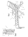
- the upper end of the rear leg 3 ends in a joint socket 13, which, as the plan view according to FIG. 4 shows, consists of two fork surface elements 17, 17 'which are spaced apart and parallel to one another.
- the fork surface elements 17, 17 ' are provided from the inside of the socket with depressions or preferably openings, which are referred to below as "pin holes" and which bear the reference number 16, 16'.
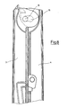
- the pin hole 16 has an outer contour, as shown in Figure 3 in plan view.
- the mortise extends transversely to the bisector W of the spreading angle ⁇ .
- the definition of "transversely” is to be understood in such a way that an angle of 90 ° to the bisector W does not necessarily have to be maintained, but rather indicates that the extension of the mortise does not extend in the direction of the bisector W.
- Different angles can be taken with respect to the bisector of the angle, which is documented by the fact that the pin hole 16 does not run exactly straight, but is a circular ring section which is rounded at the ends and points concavely toward the expansion opening.
- the pin hole 16 accordingly has a length, measured over the center sliding distance G of the pin hole, of approximately 1 ⁇ D, where D is the diameter of the pin 15 to be described.
- the "center sliding distance" of the pin is designated by G in FIG.
- a guide track 18 is provided, which consists of a smooth wall at the rear of the space between the two fork surface elements.
- the upper part of the rear leg 3 forms a support element 19 which engages under the armrest 5 when the garden furniture is later assembled.
- the other configuration of the rear leg corresponds to the usual measures to be provided in plastic production and will not be explained further here.
- FIGS. 5 and 6 show the upper section of the front leg 4 of a leg frame.
- the front leg 4 ends in its upper end in a joint head 14, which also has two fork surface elements 11, 11 'which are parallel to one another, but have a distance which is less than that of the elements 17, 17'.
- the fork surface elements 11, 11 'each have a pin 15, 15', which is made of solid or solid plastic and in the exemplary embodiment described here has a diameter D of approximately 18 mm.
- the two forked surface elements 11, 11 'provided with pins 15, 15' are inserted between the forked surface elements 17, 17 ', so that the outwardly projecting pins 15, 15' snap into the pin holes 16, 16 'and are rotatably held there.
- the fork surface elements also have a sliding nose 12 arranged above the pin 15, which, as can be seen, forms the free point of the joint head 14 which is the most distant from the center of the pin 15.
- FIG. 7 Let us now consider FIG. 7.
- the two parts 3 and 4 are joined together in the region of the joint 10. It can be seen that the pin 15 has slid into the right position in the pin hole 16. It is also fixed in this position, because the sliding lug 12 has slid over the upper part of the guide track 18, the distance between the two parts 3 and 4 increasing in the area of the joint in accordance with the curvature and the distance of the sliding lug as the spread increases . In the outermost spread position of the legs, as shown in FIG. 7, the pin 15 is therefore fixed at the extreme end of the pin hole 16 by pressure and by the stable configuration of the legs 3, 4 on the ground.
- the compatible parts sliding lug 12 and guideway 18 form a control element which is present in the region of the joint and which fixes the pivot pin 15 at one end of the pivot hole 16 when the legs are in the extreme spread position.
- the sliding lug 12 disengages, that is, it no longer slides on the guide track 18, so that the position of the pin 15 is free and this can move back and forth within the pin hole 16. This ensures that when the legs are folded or are about to be folded, there is a certain amount of play corresponding to the length of the pin hole, so that fingers or the like which get between the leg surface can no longer get stuck.
- FIGS. 8 and 9 The space-saving version is shown in FIG. 8.
- the pin 15 is in the left position of the pin hole 16 and thus enables the legs 3, 4 to lie firmly on one another.
- a security area 20 is open, which results from the fact that the pin 15 has moved from the position according to FIG. 8 into the right position according to FIG. 9 within the pin hole 16 by simply pulling apart, which is possible without effort.
- no "hooking" or the like is required.
- the guide element intervenes automatically as soon as the sliding lug comes into contact with the guide track 18.
- control member can comprise a guide web attached to the joint head, over which a guide claw attached to the joint socket overlaps.
- a guide claw which acts similarly to a sliding lug, only pulls.
- the guide claw pulls the two joint parts towards one another and finally brings the pin into the right position within the pin hole 16, if this is considered analogously to FIG. 7.
- this embodiment may have certain disadvantages, since when spreading apart the guide claw must first be positioned in relation to your guide bar.
- the leg frame in particular the joint part, is preferably made exclusively of plastic.
- other materials for example metal, can also be used.
- Combinations of several plastics and / or plastic / metal are also conceivable.
- the idea of the invention of a pin that can be moved to a limited extent within a pin hole can be easily realized.
Landscapes
- Health & Medical Sciences (AREA)
- Dentistry (AREA)
- General Health & Medical Sciences (AREA)
- Life Sciences & Earth Sciences (AREA)
- Engineering & Computer Science (AREA)
- Wood Science & Technology (AREA)
- Furniture Connections (AREA)
- Chairs For Special Purposes, Such As Reclining Chairs (AREA)
Applications Claiming Priority (4)
| Application Number | Priority Date | Filing Date | Title |
|---|---|---|---|
| DE9005126U | 1990-05-07 | ||
| DE9005126 | 1990-05-07 | ||
| DE4026059 | 1990-08-17 | ||
| DE4026059A DE4026059A1 (de) | 1990-05-07 | 1990-08-17 | Beingestell fuer ein klappmoebel und gelenkteil fuer ein beingestell |
Publications (2)
| Publication Number | Publication Date |
|---|---|
| EP0456008A1 true EP0456008A1 (fr) | 1991-11-13 |
| EP0456008B1 EP0456008B1 (fr) | 1994-11-02 |
Family
ID=25896002
Family Applications (1)
| Application Number | Title | Priority Date | Filing Date |
|---|---|---|---|
| EP91106012A Expired - Lifetime EP0456008B1 (fr) | 1990-05-07 | 1991-04-16 | Cadre de pied pour un meuble pliant et articulation pour ce cadre |
Country Status (2)
| Country | Link |
|---|---|
| EP (1) | EP0456008B1 (fr) |
| DE (2) | DE4026059A1 (fr) |
Cited By (3)
| Publication number | Priority date | Publication date | Assignee | Title |
|---|---|---|---|---|
| EP1371923A4 (fr) * | 2001-03-13 | 2005-04-27 | Sharp Kk | Mecanisme de came et mecanisme d'ouverture/fermeture de porte |
| CN1299620C (zh) * | 2004-12-24 | 2007-02-14 | 崔忠民 | 多功能折叠式椅子 |
| CN113891670A (zh) * | 2019-06-04 | 2022-01-04 | 野醍冷却器有限责任公司 | 便携式椅子 |
Citations (3)
| Publication number | Priority date | Publication date | Assignee | Title |
|---|---|---|---|---|
| US2789623A (en) * | 1956-04-10 | 1957-04-23 | Frank A Lisi | Collapsible chair |
| DE3319757A1 (de) * | 1982-09-14 | 1984-03-15 | Tokyo Shibaura Denki K.K., Kawasaki | Tuerscharnieranordnung fuer einen aufbewahrungsschrank |
| EP0267487A2 (fr) * | 1986-11-14 | 1988-05-18 | Karl Münkel GmbH & Co. KG. | Dispositif d'articulation pour l'utilisation entre un pied avant et un pied arrière d'un meuble pliant |
Family Cites Families (2)
| Publication number | Priority date | Publication date | Assignee | Title |
|---|---|---|---|---|
| DE3309186C1 (de) * | 1983-03-15 | 1984-04-05 | Bemico Enschede B.V., Enschede | Gelenkvorrichtung zur Anordnung zwischen Vorder- und Hinterbein eines Klappmöbels |
| DE8436612U1 (de) * | 1984-12-14 | 1985-05-23 | Heinz Kettler Metallwarenfabrik Gmbh & Co, 4763 Ense | Klappsessel |
-
1990
- 1990-08-17 DE DE4026059A patent/DE4026059A1/de active Granted
-
1991
- 1991-04-16 DE DE59103390T patent/DE59103390D1/de not_active Expired - Lifetime
- 1991-04-16 EP EP91106012A patent/EP0456008B1/fr not_active Expired - Lifetime
Patent Citations (3)
| Publication number | Priority date | Publication date | Assignee | Title |
|---|---|---|---|---|
| US2789623A (en) * | 1956-04-10 | 1957-04-23 | Frank A Lisi | Collapsible chair |
| DE3319757A1 (de) * | 1982-09-14 | 1984-03-15 | Tokyo Shibaura Denki K.K., Kawasaki | Tuerscharnieranordnung fuer einen aufbewahrungsschrank |
| EP0267487A2 (fr) * | 1986-11-14 | 1988-05-18 | Karl Münkel GmbH & Co. KG. | Dispositif d'articulation pour l'utilisation entre un pied avant et un pied arrière d'un meuble pliant |
Cited By (4)
| Publication number | Priority date | Publication date | Assignee | Title |
|---|---|---|---|---|
| EP1371923A4 (fr) * | 2001-03-13 | 2005-04-27 | Sharp Kk | Mecanisme de came et mecanisme d'ouverture/fermeture de porte |
| US7506474B2 (en) | 2001-03-13 | 2009-03-24 | Sharp Kabushiki Kaisha | CAM mechanism for shifting a rotary member supported on a base member when the rotary member is opened and closed |
| CN1299620C (zh) * | 2004-12-24 | 2007-02-14 | 崔忠民 | 多功能折叠式椅子 |
| CN113891670A (zh) * | 2019-06-04 | 2022-01-04 | 野醍冷却器有限责任公司 | 便携式椅子 |
Also Published As
| Publication number | Publication date |
|---|---|
| DE4026059C2 (fr) | 1992-02-20 |
| DE4026059A1 (de) | 1991-11-14 |
| DE59103390D1 (de) | 1994-12-08 |
| EP0456008B1 (fr) | 1994-11-02 |
Similar Documents
| Publication | Publication Date | Title |
|---|---|---|
| DE69402184T2 (de) | Faltbare einheit zum tragen oder transport einer person | |
| DE3854621T2 (de) | Verriegelungsvorrichtung für einen Kinderlaufstall. | |
| CH249833A (de) | Verstellbares Ruhemöbel. | |
| EP1388309B1 (fr) | Articulation, particulièrement pour chaises longues | |
| DE10128614C1 (de) | Unterteil für ein Baby-Klappbett | |
| DE102022113145A1 (de) | Befestigungsvorrichtung mit drehbegrenzungsfunktion und kindertransporter mit der befestigungsvorrichtung | |
| DE3540871A1 (de) | Gelenkmechanismus fuer einen zusammenklappbaren kinderwagen | |
| DE3304801A1 (de) | Schlitten | |
| DE69808058T2 (de) | Verschliessbare Gelenkverbindung für Kleinkinderbett | |
| EP0456008B1 (fr) | Cadre de pied pour un meuble pliant et articulation pour ce cadre | |
| DE20009655U1 (de) | Klappbares Gestell für einen Laufstall | |
| EP4478914B1 (fr) | Cadre de lit | |
| DE816588C (de) | Klappstuhl | |
| DE9311345U1 (de) | Stuhl | |
| DE653795C (de) | Sofabett mit einem eingebauten, zusammenlegbaren Bettrahmen | |
| DE3127310C2 (fr) | ||
| DE10018567A1 (de) | Lattenrost | |
| DE10307738B4 (de) | Neigungsverstellvorrichtung für mindestens einen Teil einer Liege- oder Sitzfläche | |
| EP0305578B1 (fr) | Dispositif de fixation pour un rétroviseur extérieur rabattable pour véhicules | |
| DE10219539A1 (de) | Sitzmöbel | |
| DE102017107367A1 (de) | Mechanismus zum Herausschieben eines Sitzes | |
| DE3920908A1 (de) | Sitz-und/oder liegemoebel | |
| DE1942152C3 (de) | Stapelbarer Klappstuhl | |
| DE102018111215A1 (de) | Sitzmöbel | |
| DE345018C (de) | Spielfigur, bei der ein Koerper mit offener flacher Hoehlung auf Stuetzen gesteckt ist |
Legal Events
| Date | Code | Title | Description |
|---|---|---|---|
| PUAI | Public reference made under article 153(3) epc to a published international application that has entered the european phase |
Free format text: ORIGINAL CODE: 0009012 |
|
| AK | Designated contracting states |
Kind code of ref document: A1 Designated state(s): BE DE FR GB IT NL |
|
| 17P | Request for examination filed |
Effective date: 19920302 |
|
| 17Q | First examination report despatched |
Effective date: 19930817 |
|
| GRAA | (expected) grant |
Free format text: ORIGINAL CODE: 0009210 |
|
| AK | Designated contracting states |
Kind code of ref document: B1 Designated state(s): BE DE FR GB IT NL |
|
| ITF | It: translation for a ep patent filed | ||
| REF | Corresponds to: |
Ref document number: 59103390 Country of ref document: DE Date of ref document: 19941208 |
|
| GBT | Gb: translation of ep patent filed (gb section 77(6)(a)/1977) |
Effective date: 19950109 |
|
| ET | Fr: translation filed | ||
| PLBE | No opposition filed within time limit |
Free format text: ORIGINAL CODE: 0009261 |
|
| STAA | Information on the status of an ep patent application or granted ep patent |
Free format text: STATUS: NO OPPOSITION FILED WITHIN TIME LIMIT |
|
| 26N | No opposition filed | ||
| REG | Reference to a national code |
Ref country code: GB Ref legal event code: IF02 |
|
| PGFP | Annual fee paid to national office [announced via postgrant information from national office to epo] |
Ref country code: GB Payment date: 20040331 Year of fee payment: 14 |
|
| PGFP | Annual fee paid to national office [announced via postgrant information from national office to epo] |
Ref country code: FR Payment date: 20040415 Year of fee payment: 14 |
|
| PGFP | Annual fee paid to national office [announced via postgrant information from national office to epo] |
Ref country code: BE Payment date: 20040527 Year of fee payment: 14 |
|
| PG25 | Lapsed in a contracting state [announced via postgrant information from national office to epo] |
Ref country code: IT Free format text: LAPSE BECAUSE OF NON-PAYMENT OF DUE FEES;WARNING: LAPSES OF ITALIAN PATENTS WITH EFFECTIVE DATE BEFORE 2007 MAY HAVE OCCURRED AT ANY TIME BEFORE 2007. THE CORRECT EFFECTIVE DATE MAY BE DIFFERENT FROM THE ONE RECORDED. Effective date: 20050416 Ref country code: GB Free format text: LAPSE BECAUSE OF NON-PAYMENT OF DUE FEES Effective date: 20050416 |
|
| PG25 | Lapsed in a contracting state [announced via postgrant information from national office to epo] |
Ref country code: BE Free format text: LAPSE BECAUSE OF NON-PAYMENT OF DUE FEES Effective date: 20050430 |
|
| BERE | Be: lapsed |
Owner name: *HARTMAN GROEP B.V. Effective date: 20050430 |
|
| GBPC | Gb: european patent ceased through non-payment of renewal fee |
Effective date: 20050416 |
|
| PG25 | Lapsed in a contracting state [announced via postgrant information from national office to epo] |
Ref country code: FR Free format text: LAPSE BECAUSE OF NON-PAYMENT OF DUE FEES Effective date: 20051230 |
|
| REG | Reference to a national code |
Ref country code: FR Ref legal event code: ST Effective date: 20051230 |
|
| BERE | Be: lapsed |
Owner name: *HARTMAN GROEP B.V. Effective date: 20050430 |
|
| PGFP | Annual fee paid to national office [announced via postgrant information from national office to epo] |
Ref country code: DE Payment date: 20100423 Year of fee payment: 20 Ref country code: NL Payment date: 20100413 Year of fee payment: 20 |
|
| REG | Reference to a national code |
Ref country code: DE Ref legal event code: R071 Ref document number: 59103390 Country of ref document: DE |
|
| REG | Reference to a national code |
Ref country code: NL Ref legal event code: V4 Effective date: 20110416 |
|
| PG25 | Lapsed in a contracting state [announced via postgrant information from national office to epo] |
Ref country code: NL Free format text: LAPSE BECAUSE OF EXPIRATION OF PROTECTION Effective date: 20110416 |
|
| PG25 | Lapsed in a contracting state [announced via postgrant information from national office to epo] |
Ref country code: DE Free format text: LAPSE BECAUSE OF EXPIRATION OF PROTECTION Effective date: 20110416 |