EP0456009B1 - Tuyau à jet avec éléments de fixation pour appareil de nettoyage à haute pression - Google Patents
Tuyau à jet avec éléments de fixation pour appareil de nettoyage à haute pression Download PDFInfo
- Publication number
- EP0456009B1 EP0456009B1 EP91106014A EP91106014A EP0456009B1 EP 0456009 B1 EP0456009 B1 EP 0456009B1 EP 91106014 A EP91106014 A EP 91106014A EP 91106014 A EP91106014 A EP 91106014A EP 0456009 B1 EP0456009 B1 EP 0456009B1
- Authority
- EP
- European Patent Office
- Prior art keywords
- jet pipe
- pipe
- enlarged portion
- plastic
- ring
- Prior art date
- Legal status (The legal status is an assumption and is not a legal conclusion. Google has not performed a legal analysis and makes no representation as to the accuracy of the status listed.)
- Expired - Lifetime
Links
- 238000000746 purification Methods 0.000 title 1
- 239000004033 plastic Substances 0.000 claims description 11
- 239000004952 Polyamide Substances 0.000 claims description 4
- 238000004140 cleaning Methods 0.000 claims description 4
- 239000003365 glass fiber Substances 0.000 claims description 4
- 229920002647 polyamide Polymers 0.000 claims description 4
- 239000002184 metal Substances 0.000 description 5
- 230000006835 compression Effects 0.000 description 4
- 238000007906 compression Methods 0.000 description 4
- 238000004519 manufacturing process Methods 0.000 description 3
- 238000010276 construction Methods 0.000 description 2
- 238000003780 insertion Methods 0.000 description 2
- 230000037431 insertion Effects 0.000 description 2
- 239000007921 spray Substances 0.000 description 2
- 238000000926 separation method Methods 0.000 description 1
- 230000007704 transition Effects 0.000 description 1
Images
Classifications
-
- F—MECHANICAL ENGINEERING; LIGHTING; HEATING; WEAPONS; BLASTING
- F16—ENGINEERING ELEMENTS AND UNITS; GENERAL MEASURES FOR PRODUCING AND MAINTAINING EFFECTIVE FUNCTIONING OF MACHINES OR INSTALLATIONS; THERMAL INSULATION IN GENERAL
- F16L—PIPES; JOINTS OR FITTINGS FOR PIPES; SUPPORTS FOR PIPES, CABLES OR PROTECTIVE TUBING; MEANS FOR THERMAL INSULATION IN GENERAL
- F16L37/00—Couplings of the quick-acting type
- F16L37/24—Couplings of the quick-acting type in which the connection is made by inserting one member axially into the other and rotating it to a limited extent, e.g. with bayonet-action
- F16L37/244—Couplings of the quick-acting type in which the connection is made by inserting one member axially into the other and rotating it to a limited extent, e.g. with bayonet-action the coupling being co-axial with the pipe
- F16L37/252—Couplings of the quick-acting type in which the connection is made by inserting one member axially into the other and rotating it to a limited extent, e.g. with bayonet-action the coupling being co-axial with the pipe the male part having lugs on its periphery penetrating into the corresponding slots provided in the female part
-
- B—PERFORMING OPERATIONS; TRANSPORTING
- B05—SPRAYING OR ATOMISING IN GENERAL; APPLYING FLUENT MATERIALS TO SURFACES, IN GENERAL
- B05B—SPRAYING APPARATUS; ATOMISING APPARATUS; NOZZLES
- B05B15/00—Details of spraying plant or spraying apparatus not otherwise provided for; Accessories
- B05B15/60—Arrangements for mounting, supporting or holding spraying apparatus
- B05B15/65—Mounting arrangements for fluid connection of the spraying apparatus or its outlets to flow conduits
-
- B—PERFORMING OPERATIONS; TRANSPORTING
- B08—CLEANING
- B08B—CLEANING IN GENERAL; PREVENTION OF FOULING IN GENERAL
- B08B3/00—Cleaning by methods involving the use or presence of liquid or steam
- B08B3/02—Cleaning by the force of jets or sprays
- B08B3/026—Cleaning by making use of hand-held spray guns; Fluid preparations therefor
- B08B3/028—Spray guns
-
- B—PERFORMING OPERATIONS; TRANSPORTING
- B08—CLEANING
- B08B—CLEANING IN GENERAL; PREVENTION OF FOULING IN GENERAL
- B08B2203/00—Details of cleaning machines or methods involving the use or presence of liquid or steam
- B08B2203/02—Details of machines or methods for cleaning by the force of jets or sprays
- B08B2203/0247—Hose joints, e.g. quick joints, rotating joints
Definitions
- the invention relates to a jet pipe for high-pressure cleaning devices with an axial, cylindrical hole with a widening for receiving a pipe socket forming part of a component to be connected to the jet pipe, which jet pipe has screw parts belonging to a bayonet fitting.
- Jet pipes of the type mentioned must be detachably connected to other parts of a high-pressure cleaning device, for example a spray gun.
- Bayonet locks are applicable for such connections.
- they since they have to be mechanically stable, they are normally of complex construction and consist of a large number of parts, which is particularly true for the connecting element with the screw wedges. This makes the bayonet lock expensive and prone to failure.
- EP-A2-0 099 033 describes a metal jet pipe which can be connected to a hose line via a complicated bayonet lock.
- the invention has for its object to design the beam tube so that the bayonet lock - and in particular the part with the screw wedges - consists of a few parts, is simple and yet mechanically stable.
- the counter-holder To hold the counter-holder, it is advantageous if it has two mutually opposite, radially projecting projections which, when the counter-holder is pressed into the widening, snap into correspondingly designed and localized recesses in the widening.
- the attachment of the O-ring therefore only requires two additional parts, namely the O-ring and the counter holder.
- the attachment of the counter holder to the jet pipe is extremely simple thanks to the properties of the plastic and that, since the counter holder and the O-ring are firmly connected to the jet pipe, the number of parts which the operator handles must, not increased. It can be provided that the axial hole is lined with a metallic inner wall.
- the plastic is glass fiber reinforced polyamide.
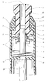
- a jet pipe 1 which is made of plastic, preferably of glass fiber reinforced polyamide.
- Two screw wedges 4 protrude radially from the end of the jet pipe 1 shown.
- the jet pipe 1 has an axial cylindrical hole 2 which merges into an expansion 10 at the end of the jet pipe shown.
- an O-ring 9 is inserted, which is fixed by means of a counter-holder 11 which fits into the widening 10.
- the counter-holder 11 has two mutually opposite projections 13 which, when the counter-holder is pressed into the widening 10, snap into correspondingly designed and positioned recesses 12 in the wall of the widening 10. The counter holder 11 and the O-ring 9 are thus firmly integrated into the jet pipe 1.
- the component 3 has an opening 15 at the end shown, the cross section of which is equal to the cross section of the section of the jet pipe 1 which has the screw wedges 4.
- the opening 15 is followed by a cylindrical recess 5 with a circular cross section, which - with a step 7 - borders the opening 15 and an intermediate wall 16, to which further sections of the component 3 adjoin.
- the diameter of the recess 5 is greater than or equal to the largest diameter of the jet pipe cross section including the screw wedges 4.
- a pipe socket 8 which connects to an opening 17 in the intermediate wall 16 and which still protrudes somewhat into the opening 15.
- a metal compression spring 6 in the recess 5, which surrounds the pipe socket 8.
- a pipe 18 connects concentrically with the pipe socket 8 and the opening 17.
- the component 3 usually consists of two halves produced separately from one another, the pipe socket 8 being integrated into one half. This type of production is indicated because component 3 is normally part of a larger whole and it would be too complicated to produce a large unit in one piece. The separation into two halves is also advantageous because the recess 5 can then be produced more easily and the compression spring 6 can be inserted more easily.
- the two halves are connected to one another for example by screws, for which the two holes 14 are provided.
- the component 3 is, for example, part of a spray gun, which is connected to the high-pressure cleaning device via a pressure hose.
- the connection between the jet pipe 1 and the component 3 is very simple. First, the jet pipe 1 is inserted into the component 3 and thus also the pipe socket 8 into the hole 2, the insertion position being visible to the operator from the outside. Then the jet pipe is rotated against component 3. When disconnecting, the two steps are done in reverse order.
- the wedges 4 are pressed by means of the compression spring 6 against the step 7 between the recess 5 and the opening 15.
- the surfaces of the screw wedges 4 can be laid out over a large area.
- the tightness of the connection between the pipe socket 8 and the hole 2 is achieved by means of the O-ring 9.
- the operator only has to take two parts in hand, the jet pipe 1 and the component 3. Apart from the compression spring 6, which is made of metal, the jet pipe 1 and the component 3 are made of plastic. As a result, the connection is electrically and thermally insulating.
- the jet pipe 1 is made entirely of plastic, but it is possible to line the axial hole 2 with an inner wall 19 made of metal, so that a layered structure metal / plastic results. In the drawing, this is shown in dashed lines on part of the elongated axial hole 2.
Landscapes
- Engineering & Computer Science (AREA)
- General Engineering & Computer Science (AREA)
- Mechanical Engineering (AREA)
- Nozzles (AREA)
- Cleaning By Liquid Or Steam (AREA)
Claims (4)
- Tube de pulvérisation (1) pour des appareils de nettoyage à haute pression, comportant un trou cylindrique axial (2) avec un élargissement (10) pour la réception d'un manchon de tube (8) formant une partie d'un composant (3) à relier au tube de pulvérisation (1) qui présente des coins à vis (4) faisant partie d'un obturateur à baïonnette, caractérisé en ce que le tube de pulvérisation (1) est constitué en matière plastique, en ce que les coins à vis (4) sont injectés en saillie directe radiale, et en ce que dans l'élargissement (10) à l'extrémité de la réception du trou (2) est posé un joint torique (9) qui est retenu par un organe opposé de maintien (11) ajusté dans l'élargissement (10).
- Tube de pulvérisation selon la revendication 1, caractérisé en ce que l'organe opposé de maintien (11) présente deux saillies (13) opposées l'une à l'autre et s'écartant radialement qui, lorsque l'organe opposé de maintien (11) est pressé dans l'élargissement (10), s'encliquettent dans des creux localisés et réalisés en correspondance (12) dans l'élargissement (10).
- Tube de pulvérisation selon l'une ou l'autre des revendications 1 et 2, caractérisé en ce que le trou axial (2) est revêtu d'une paroi intérieure métallique (19).
- Tube de pulvérisation selon l'une quelconque des revendications précédentes, caractérisé en ce que la matière plastique est du polyamide renforcé par des fibres de verre.
Applications Claiming Priority (2)
| Application Number | Priority Date | Filing Date | Title |
|---|---|---|---|
| DE4014824 | 1990-05-09 | ||
| DE4014824 | 1990-05-09 |
Publications (2)
| Publication Number | Publication Date |
|---|---|
| EP0456009A1 EP0456009A1 (fr) | 1991-11-13 |
| EP0456009B1 true EP0456009B1 (fr) | 1994-09-07 |
Family
ID=6406000
Family Applications (1)
| Application Number | Title | Priority Date | Filing Date |
|---|---|---|---|
| EP91106014A Expired - Lifetime EP0456009B1 (fr) | 1990-05-09 | 1991-04-16 | Tuyau à jet avec éléments de fixation pour appareil de nettoyage à haute pression |
Country Status (3)
| Country | Link |
|---|---|
| EP (1) | EP0456009B1 (fr) |
| DE (1) | DE59102799D1 (fr) |
| DK (1) | DK0456009T3 (fr) |
Citations (1)
| Publication number | Priority date | Publication date | Assignee | Title |
|---|---|---|---|---|
| EP0234465A2 (fr) * | 1986-02-18 | 1987-09-02 | Armaturenfabrik Hermann Voss GmbH + Co. | Dispositif de connexion enfichable avec verrouillage de torsion |
Family Cites Families (1)
| Publication number | Priority date | Publication date | Assignee | Title |
|---|---|---|---|---|
| DE3226571C2 (de) * | 1982-07-16 | 1984-05-03 | Alfred Kärcher GmbH & Co, 7057 Winnenden | Verbindungsstück für Schlauchleitungen von Hochdruckreinigungs- und -sprühgeräten |
-
1991
- 1991-04-16 DK DK91106014.3T patent/DK0456009T3/da active
- 1991-04-16 DE DE59102799T patent/DE59102799D1/de not_active Expired - Lifetime
- 1991-04-16 EP EP91106014A patent/EP0456009B1/fr not_active Expired - Lifetime
Patent Citations (1)
| Publication number | Priority date | Publication date | Assignee | Title |
|---|---|---|---|---|
| EP0234465A2 (fr) * | 1986-02-18 | 1987-09-02 | Armaturenfabrik Hermann Voss GmbH + Co. | Dispositif de connexion enfichable avec verrouillage de torsion |
Non-Patent Citations (1)
| Title |
|---|
| VDI-Nachrichten Nr. 12, 22.03.85, Seite 22 "Technische Kunststoffe" * |
Also Published As
| Publication number | Publication date |
|---|---|
| DE59102799D1 (de) | 1994-10-13 |
| DK0456009T3 (da) | 1994-10-10 |
| EP0456009A1 (fr) | 1991-11-13 |
Similar Documents
| Publication | Publication Date | Title |
|---|---|---|
| DE3531926C2 (fr) | ||
| EP3379129B1 (fr) | Raccord | |
| EP0414002B1 (fr) | Outil de soudage | |
| EP2957681A2 (fr) | Robinetterie sanitaire a systeme de tuyau interne | |
| DE19654435A1 (de) | Anordnung zur steckbaren Verbindung von Rohren mit Armaturen oder Fittings | |
| AT3080U1 (de) | Vorrichtung zum verbinden eines rohrstutzens, rohrförmigen armaturenteils oder fittings mit einem rohr | |
| EP0549860B1 (fr) | Dispositif d'accouplement de deux conduites, en particulier pour des conduites de carburant | |
| DE102017110764A1 (de) | Vorrichtung zum Befestigen eines Sanitärgegenstandes und Verwendung einer solchen Vorrichtung | |
| EP1264127A1 (fr) | Robinet d'arret rotatif pour embout d'enfichage avec raccord coude | |
| DE8032468U1 (de) | Aufnahmeelement zur rasch kuppelnden verbindung von schlaeuchen | |
| EP0456009B1 (fr) | Tuyau à jet avec éléments de fixation pour appareil de nettoyage à haute pression | |
| DE8817020U1 (de) | Lösbare Schnell-Steckverbindung | |
| DE9214524U1 (de) | Elektrische Lampenfassung aus Kunststoff | |
| EP1703192B1 (fr) | Raccord à baïonnette | |
| DE19715293B4 (de) | Steckverbindung für Rohrleitungen | |
| DE19508638C2 (de) | Handbrause | |
| EP0928390B1 (fr) | Tuyau souple pour haute pression pourvu d'un raccord permettant son raccordement a une partie de raccordement correspondante | |
| DE9005273U1 (de) | Strahlrohr mit Verbindungselement für Hochdruckreinigungsgeräte | |
| DE3418602A1 (de) | Verbindung von rohrfoermigen stuetzelementen aus pappe o.dgl., insbesondere fuer verkaufsstaender | |
| EP0687848B1 (fr) | Raccord notamment pour dispositifs sanitaires et d'alimentation, tuyaux ou similaire | |
| DE69600824T2 (de) | Rohrverbindung | |
| EP1031781A2 (fr) | Raccord d'un tuyau à une pièce de connexion ou de liaison d'une canalisation | |
| DE202005020263U1 (de) | Mehrfachkupplung für Medienleitungen | |
| DE3721679A1 (de) | Steckanschluss | |
| DE202004005278U1 (de) | Verbindungselement zum Verbinden von zwei Wellrohren |
Legal Events
| Date | Code | Title | Description |
|---|---|---|---|
| PUAI | Public reference made under article 153(3) epc to a published international application that has entered the european phase |
Free format text: ORIGINAL CODE: 0009012 |
|
| AK | Designated contracting states |
Kind code of ref document: A1 Designated state(s): DE DK IT |
|
| 17P | Request for examination filed |
Effective date: 19911130 |
|
| 17Q | First examination report despatched |
Effective date: 19920917 |
|
| GRAA | (expected) grant |
Free format text: ORIGINAL CODE: 0009210 |
|
| ITF | It: translation for a ep patent filed | ||
| AK | Designated contracting states |
Kind code of ref document: B1 Designated state(s): DE DK IT |
|
| REG | Reference to a national code |
Ref country code: DK Ref legal event code: T3 |
|
| REF | Corresponds to: |
Ref document number: 59102799 Country of ref document: DE Date of ref document: 19941013 |
|
| PLBE | No opposition filed within time limit |
Free format text: ORIGINAL CODE: 0009261 |
|
| STAA | Information on the status of an ep patent application or granted ep patent |
Free format text: STATUS: NO OPPOSITION FILED WITHIN TIME LIMIT |
|
| 26N | No opposition filed | ||
| PGFP | Annual fee paid to national office [announced via postgrant information from national office to epo] |
Ref country code: DK Payment date: 20100412 Year of fee payment: 20 |
|
| PGFP | Annual fee paid to national office [announced via postgrant information from national office to epo] |
Ref country code: DE Payment date: 20100526 Year of fee payment: 20 Ref country code: IT Payment date: 20100419 Year of fee payment: 20 |
|
| REG | Reference to a national code |
Ref country code: DE Ref legal event code: R071 Ref document number: 59102799 Country of ref document: DE |
|
| REG | Reference to a national code |
Ref country code: DK Ref legal event code: EUP |
|
| PG25 | Lapsed in a contracting state [announced via postgrant information from national office to epo] |
Ref country code: DE Free format text: LAPSE BECAUSE OF EXPIRATION OF PROTECTION Effective date: 20110416 |